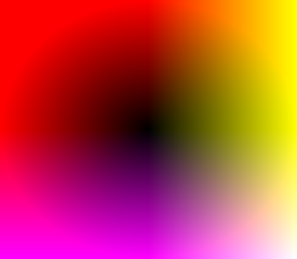
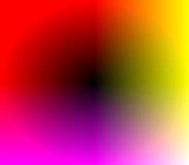
Default identity polar displacement map.
call %PICTBAT%identEllipseAbsDispMap ^ 267x233 pdd_ident1.miff
Distortion using polar coordinates directly.
This page derives, describes, verifies and demonstrates a number of polar transformations.
This page is mostly about distorting between an ellipse and a shape. For the common requirement of distorting between the rectangular boundary of an image and a shape, see Radial distortions: Rect to shape.
See also the Shape centres page.
There is currently a bug in "-function polynomial" when used with OpenCL. See ImageMagick/issues/2404. Pending the bug fix, we disable OpenCL when running commands on this page.
set MAGICK_OCL_DEVICE=false
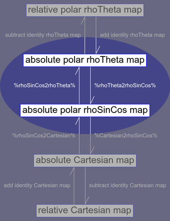
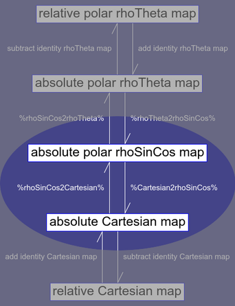
A Cartesian map defines displacements in terms of x and y, which are recorded in the red and green channels of the map image. There are two types of Cartesian maps:
magick image.png abs_map.png -compose Distort -composite out.png
magick image.png rel_map.png -compose Displace -composite out.png
We can convert between absolute and relative maps by adding or subtracting an identity absolute Cartesian map.
A polar map defines displacements in terms of ρ and θ (rho and theta) with respect to a given centre and direction. These maps can also be relative or absolute. We can record ρ and θ in the red and green channels (called a rhoTheta encoding), but it can be beneficial to use three colour channels (a rhoSinCos encoding).
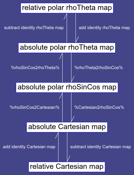
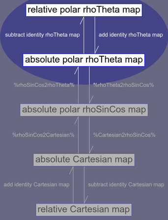
We can summarise the map types, and the conversions between them, in a diagram:
The usual IM distortion/displacement is Cartesian: the distortion map defines the X and Y coordinates to be used to lookup the colour to be used in the output image. Sometimes polar distortion is more suitable. Polar distortions shows how we can do this indirectly, by transforming polar images to Cartesian, distorting that, and converting back to polar. When that page was written, the "-fx" operation was slow.
As "-fx" performance has improved, it is sensible to do the polar distortion directly, using a polar distortion map.
As usual, these are pull maps: each pixel in the map stores coordinates in the source image from which the colour should be copied to this location.
The maps store polar coordinates ρ and θ (rho and theta). ρ represents a relative distance from a centre. ρ is 0.0 at the centre, increasing to 1.0 at the edge of the map. (As usual, "1.0" means "1.0 times QuantumRange".) The map edge is usually an ellipse, or part of an ellipse. ρ can be greater than 1.0, because the image may extend beyond the map edge. θ is a polar angle, between 0° and 360°. My usual convention is that 0° and 360° are at the top, in "north" position, where y is smallest (like a magnetic compass, or a clock), and θ increases clockwise (ditto). (Beware: some writers use different conventions, eg that 0° is in the east position, where y is 0.0.)
θ could be defined in one of two ways:
We will use the second definition.
We store ρ in the red channel, and θ in the green channel. The blue channel is irrelevant, but we will set it to zero. I call this a rhoTheta encoding. It has discontinuity at 0° and 360°, so it can't be supersampled or undergo a transformation that would mix pixels.
Instead, we can store:
I call this 3-channel encoding a rhoSinCos map. This map has no inherent discontinuity so can be rescaled etc without problems. We can recover θ from this map, if we need to. Trigonometric functions can be negative, so the processing needs to use HDRI, and files must be capable of storing negative numbers. We could scale and shift the trig functions so the output was never negative, but that would add layers of complexity. We generally want high precision for displacements, so 32-bit floats are already indicated.
The rhoSinCos encoding does the sin(θ) and -cos(θ) functions and multiplies each by ρ when the map is built, so this is not needed when applying the map. Hence if one map is to be used on many images, this will save on processing.
An absolute map records, at each destination pixel, the polar coordinates of the source colour. A relative map records the the polar coordinates of the source colour relative to the coordinates of the destination pixel.
An absolute map Aa, and the corresponding relative map Ra, and the identity absolute map Ia, that are all encoded as rhoTheta, with the same sizes and same centres, are related by:
Ra = Aa - Ia

Aa = Ra + Ia
Arithmetic on θ, but not ρ, should be modulus 360°.
The identity relative polar displacement map Ir has ρ=0 and θ=0 for all pixels. This can be conveniently built as a black image.
Relative maps, like absolute maps, should be stored in floating-point formats.
We can set ρ=1.0 either at the centre of the edges or at the corners.
The script identEllipseAbsDispMap.bat creates an image that is an ellipsoidal polar displacement map.
| Parameter | Description |
|---|---|
| %1 | WxH, width and height, with a "x" between them.
Default 150x100. |
| %2 | Output filename.
Default: ieadm.png. |
| %3 | Centre CXxCY.
Default (W-1)/2,(H-1)/2. |
| %4 | Radius RXxRY, or one of: nearCorner, farCorner, nearEdge, farEdge.
Default: nearEdge. |
| %5 | Map type: rhoTheta or rhoSinCos.
Default: rhoSinCos. |
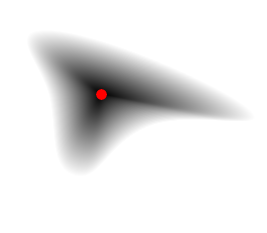
The default has the ellipse centre at the image centre, with the ellipse touching all four image edges ("nearEdge"), so ρ is 1.0 at the centre of each edge, and the data is stored in the "rhoSinCos" encoding.
|
Default identity polar displacement map. call %PICTBAT%identEllipseAbsDispMap ^ 267x233 pdd_ident1.miff |
|
We show a PNG version of the map, so pixel values are clamped. We can show the range of values:
%IMG7%magick ^
  pdd_ident1.miff ^
  -format "min=%%[fx:minima] mean=%%[fx:mean] max=%%[fx:maxima] SD=%%[fx:standard_deviation]" ^
  info:
min=-1 mean=0.256093 max=1.41421 SD=0.481787
We see that values exceed the nominal range of 0.0 to 1.0:
We distort an image with a map using a %[fx:...] expression. We put the expressions into environment variables for convenience. One expression is for rhoTheta encodings, and the other is for rhoSinTheta. They are both for absolute (not relative) maps.
set FxRhoTheta=^
  ANG = v.g * %%[fx:2*pi]; ^
  p { ^
      %%[fx:(u.w-1)/2] * (1 + sin(ANG) * v.r), ^
      %%[fx:(u.h-1)/2] * (1 - cos(ANG) * v.r)  ^
    }

set FxRhoSinCos=^
  p { ^
      %%[fx:(u.w-1)/2] * (1 + v.g), ^
      %%[fx:(u.h-1)/2] * (1 + v.b)  ^
    }
Expressions "2*pi" and "(u.w-1)/2" and "(u.h-1)/2" are constant within each image. By putting them in nested %[fx:...] expressions, they are evaluated only once per image, instead of once per pixel.
The first image, u, is the image to be distorted. The second image, v, is the distortion map.
"(u.w-1)/2" is the semi-width, in image (not pixel) units. The expressions do an absolute look-up p{X,Y} where:
We could further improve the performance of distortions by pre-calculating the semi-width and semi-height, so the rhoSinCos expression was simply p{v.g,v.b}, but that would reduce flexibility.
We verify that distorting an image with an identity map doesn't change it:
|
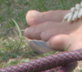
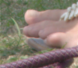
Distort toes.png with default identity map. %IMG7%magick ^ toes.png ^ pdd_ident1.miff ^ -fx "%FxRhoSinCos%" ^ -define quantum:format=floating-point -depth 32 ^ pdd_ident_toes.miff |

|
How much has the image distorted?
%IMG7%magick compare -metric RMSE toes.png pdd_ident_toes.miff NULL:
0.478341 (7.29902e-06)
There is practically no distortion.
We can instead use the simpler rhoTheta map. This map doesn't include the sin and cos calculations, so we need to do them when using the map.
|
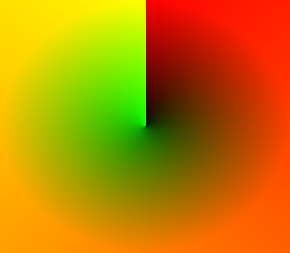
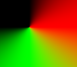
Default identity polar displacement map, rhoTheta. call %PICTBAT%identEllipseAbsDispMap ^ 267x233 pdd_ident_rt.miff . . rhoTheta |
|
|
Distort toes.png with identity map. %IMG7%magick ^ toes.png ^ pdd_ident_rt.miff ^ -fx "%FxRhoTheta%" ^ -define quantum:format=floating-point -depth 32 ^ pdd_ident_rt_toes.miff |

|
How much has the image distorted?
%IMG7%magick compare -metric RMSE toes.png pdd_ident_rt_toes.miff NULL:
0.478327 (7.2988e-06)
Again, there is practically no distortion.
|
Default identity polar displacement map, rhoSinCos2. call %PICTBAT%identEllipseAbsDispMap ^ 267x233 pdd_ident_rsc2.miff . . rhoSinCos2 |

|
|
Distort toes.png with identity map. %IMG7%magick ^ toes.png ^ pdd_ident_rsc2.miff ^ -fx "%FxRhoSinCos%" ^ -define quantum:format=floating-point -depth 32 ^ pdd_ident_rsc2_toes.miff |
|
How much has the image distorted?
%IMG7%magick compare -metric RMSE toes.png pdd_ident_rsc2_toes.miff NULL:
0.131456 (2.0059e-06)
Again, there is practically no distortion. The three methods have essentially the same, virtually zero, distortion. rhoSinCos2 involves no trig functions, so is likely to be the fastest.
We could also create the inverse of a polar displacement map, to convert from an arbitrary shape to an ellipse.
The identity map is built using an ellipsoidal gradient that is large enough that if the centre was in one corner of the image, the ellipse would pass through the opposite corner. The ellipse also has the same aspect ratio as the image. To make both these conditions true, the script sets the radii to (W*sqrt(2), H*sqrt(2)) for the elliptical gradient. (As we use image coordinates, these are actually ((W-1)*sqrt(2), (H-1)*sqrt(2)).) Then it divides the gradient by the value that it finds at the required location: the nearest edge, or whatever.
ASIDE: Constraining an ellipse to pass through a given point.
Where does ((W-1)*sqrt(2), (H-1)*sqrt(2)) come from?
The general equation for an ellipse centred at the origin is:
x2 + y2 = 1
a2   b2
... where a and b are the axes parallel to the x and y axes. a and b are used directly in:
-define gradient:radii=A,B
... where A and B are numbers. They cannot be %[fx:...] expressions.
For an ellipse to go through a corner point (w/2,h/2) what should a and b be?
An infinite number of ellipses will do this. We have a further condition: the aspect ratios of the ellipse and the image should be the same: a/b = w/h. So a = b*w/h.
So:
 (w/2)2   + (h/2)2 = 1
(b*w/h)2      b2
Multiply by b2:
(w/2)2 + (h/2)2 = b2
(w/h)2

(1/2)2 + (h/2)2 = b2
(1/h)2

(h)2 + (h/2)2 = b2
(2)2

b2 = 2*(h/2)2
b2 = h2/2
b = h / sqrt(2)
But:
a = b*w/h
So:
a = w / sqrt(2)
For the case where the origin is at (0,0) and we want the ellipse to pass through the opposite corner, we need to double these values, so:
a = w * sqrt(2)
b = h * sqrt(2)
QED.
We define two transformations as environment variables that can be used in IM commands.
set rhoTheta2rhoSinCos= ^
  -channel B -fx "-cos (g * %%[fx:2*pi] ) * r" ^
  -channel G -fx "sin (g * %%[fx:2*pi] ) * r" ^
  +channel

set rhoSinCos2rhoTheta= ^
  -channel G -fx "0.5 - atan2(g,b) / %%[fx:2*pi]" ^
  -channel B -evaluate set 0 ^
  +channel
Below, we will verify the encoding round-trip.
We can convert between a rhoSinCos polar map and the usual Cartesian map. The polar map may contain values greater than 100%, so file formats should be floating-point.
We want conversions to make equivalent maps, so an image distorted by a polar map gives the same result as the image distorted by the equivalent Cartesian map.
We convert with these formulae, which are derived from the -fx expressions in Distorting with maps:
Cx = (1 + Ps) / 2
Cy = (1 + Pc) / 2
Hence:
Ps = 2 * Cx - 1
Pc = 2 * Cy - 1
ρ = hypot (Ps, Pc)
... where:
set rhoSinCos2Cartesian=^
  -function Polynomial 0.5,0.5 ^
  -channel-fx "green=>red blue=>green" ^
  -channel B -evaluate set 0 ^
  +channel

set Cartesian2rhoSinCos=^
  -channel-fx "green=>blue red=>green" ^
  -channel GB -function Polynomial 2,-1 ^
  -channel R -fx "hypot(g,b)" ^
  +channel
Below, we will verify the polar to Cartesian round-trip.
|
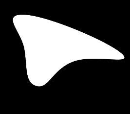
Generate an arbitrary curved shape using the acwise program. ( echo 50,30 echo 50,100 echo 250,110 echo 75,175 echo 150,125 ) | %IM7DEV%acwise ^ -i - -o - ^ --startat N -fmt curve | %IMG7%magick ^ -size 267x233 xc:Black ^ -fill White -stroke None ^ -draw @- ^ -alpha off ^ pdd_wonb.png |
|
|
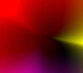
Generate a gradient. call %PICTBAT%shp2grad ^ pdd_wonb.png ^ pdd_wonb_grad.miff echo shp2gCX=%shp2gCX% shp2gCY=%shp2gCY% shp2gCX=101 shp2gCY=94 The gradient is black at the centre, white at the shape's boundary, and lighter than white outside the boundary. We also show the location of the centre. %IMG7%magick ^
pdd_wonb_grad.miff ^
-fill Red ^
-draw ^
"translate +%shp2gCX%+%shp2gCY% circle 0,0,5,0" ^
pdd_wonb_grad.png
|
|
|
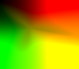
Generate a sweep, using the same centre. call %PICTBAT%ellipseSweepSinCos ^ 267x233 ^ pdd_wonb_swp.miff ^ %shp2gCX%x%shp2gCY% |
|
|
Combine the gradient and sweep to make a rhoSinCos map. %IMG7%magick ^
-define compose:clamp=off ^
( pdd_wonb_grad.miff -write mpr:RHO ) ^
pdd_wonb_swp.miff ^
-compose Multiply -composite ^
-separate -delete 2 ^
mpr:RHO -insert 0 ^
-colorspace Gray ^
-combine ^
-define quantum:format=floating-point -depth 32 ^
-set polarCX %shp2gCX% ^
-set polarCY %shp2gCY% ^
pdd_wonb_map.miff
|

|
|
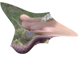
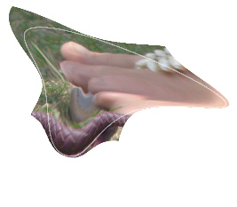
Distort with the rhoSinCos map. %IMG7%magick ^ toes.png ^ pdd_wonb_map.miff ^ -virtual-pixel None ^ -fx "%FxRhoSinCos%" ^ pdd_wonb_toes.png |
|
|
To help with understanding, create an image of the edge of the shape. %IMG7%magick ^ pdd_wonb.png ^ -edge 1 -alpha off -clamp ^ -alpha shape ^ -channel A ^ -evaluate Multiply 0.5 ^ +channel ^ pdd_edge.png |

|
|
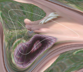
Composite the shape edge over the distortion. %IMG7%magick ^ pdd_wonb_toes.png ^ pdd_edge.png ^ -compose Over -composite ^ pdd_wonb_comp.png The ellipse of the toes image has been transformed to the shape boundary.
|

|
From shape to ellipse: convert to Cartesian, invert that, fill the holes, convert to polar. Use that as map for distortion.
|
Convert the map to Cartesian. %IMG7%magick ^ pdd_wonb_map.miff ^ -virtual-pixel None ^ %rhoSinCos2Cartesian% ^ pdd_conv_cart.miff |

|
|
Invert the Cartesian map, and fill the holes. See Process modules: invert displacement map. Filling holes could be done with relaxFill.bat, but instead we use seamless-blend. %IM7DEV%magick ^ pdd_conv_cart.miff ^ -process 'invdispmap' ^ ( +clone -alpha extract -negate +write mpr:ALP +delete ) ^ ( -clone 0 -alpha off -fill Black -colorize 100 ) ^ mpr:ALP ^ -verbose ^ -define compose:args=10000x1e-7+1000 ^ -compose seamless_blend -composite ^ +verbose ^ -alpha off ^ pdd_conv_cart_inv.miff |

|
|
Convert the inverted Cartesian map to polar. %IMG7%magick ^ pdd_conv_cart_inv.miff ^ %Cartesian2rhoSinCos% ^ pdd_wonb_map_inv.miff |
|
|
Distort the distorted toes with the inverted polar map. %IMG7%magick ^ pdd_wonb_toes.png ^ pdd_wonb_map_inv.miff ^ -fx "%FxRhoSinCos%" ^ pdd_wmi_toes.miff if ERRORLEVEL 1 exit /B 1 %IMG7%magick compare ^ -metric RMSE ^ toes.png pdd_wmi_toes.miff ^ NULL: 1295.7 (0.0197711) |
|
The round-trip, distorting the toes image to the shape then distorting back, is imperfect because the initial distortion has shrunk parts of the image by a linear factor around four. Shrinking an image loses detail that cannot be recovered by enlarging.
For convenience, we could write a script that takes two inputs, an image and a white-on-black mask that defines a shape, and makes an output that distorts the image so what was on the shape boundary becomes an ellipse.
Check that:
|
Distort a displacement map with its own inverse, and compare to identity map. %IMG7%magick ^ pdd_wonb_map.miff ^ pdd_wonb_map_inv.miff ^ -fx "%FxRhoSinCos%" ^ -define quantum:format=floating-point -depth 32 ^ pdd_disp_own_inv.miff if ERRORLEVEL 1 exit /B 1 %IMG7%magick compare ^ -metric RMSE ^ pdd_ident1.miff pdd_disp_own_inv.miff ^ NULL: 117.608 (0.00179459) |
|
Yes, this is fairly accurate.
Above, we showed environment variables for converting between rhoTheta and rhoSinCos. We can use those environment variables like this:
Convert rhoSinCos to rhoTheta:
%IMG7%magick ^
  pdd_wonb_map.miff ^
  %rhoSinCos2rhoTheta% ^
  -define quantum:format=floating-point -depth 32 ^
  pdd_rt.miff
Convert that back to rhoSinCos:
%IMG7%magick ^
  pdd_rt.miff ^
  %rhoTheta2rhoSinCos% ^
  -define quantum:format=floating-point -depth 32 ^
  pdd_rsc.miff
Check the round-trip:
%IMG7%magick compare -metric RMSE pdd_wonb_map.miff pdd_rsc.miff NULL:
0.589541 (8.99582e-06)
The round-trip between rhoTheta and rhoSinCos is accurate.
From a polar rhoSinCos map, make an absolute Cartesian map.
set SRC_POL_MAP=pdd_wonb_map.miff %IMG7%magick ^ %SRC_POL_MAP% ^ %rhoSinCos2Cartesian% ^ pdd_p_cart_map.miff |
|
Distort an image with the absolute Cartesian map. Compare with distortion made with polar map.
%IMG7%magick ^
  toes.png ^
  pdd_p_cart_map.miff ^
  -virtual-pixel None ^
  -compose Distort -composite ^
  -define quantum:format=floating-point -depth 32 ^
  pdd_pcm_toes.miff

%IMG7%magick ^
  compare -metric RMSE ^
  pdd_wonb_toes.png ^
  pdd_pcm_toes.miff NULL:
10.8056 (0.000164882) |

|
From the Cartesian map, make a rhoSinCos polar map. Compare this new polar map with the original rhoSinCos map.
%IMG7%magick ^
  pdd_p_cart_map.miff ^
  %Cartesian2rhoSinCos% ^
  pdd_p_cart_pol_map.miff

%IMG7%magick ^
  compare -metric RMSE ^
  pdd_wonb_map.miff ^
  pdd_p_cart_pol_map.miff NULL:
0.570506 (8.70536e-06) The round-trip from polar to Cartesian and back to polar is virtually exact. |

|
Distort the image with new polar map. Compare with distortion made with original polar map.
%IMG7%magick ^
  toes.png ^
  pdd_p_cart_pol_map.miff ^
  -virtual-pixel None ^
  -fx "%FxRhoSinCos%" ^
  -define quantum:format=floating-point -depth 32 ^
  pdd_pcpm_toes.miff

%IMG7%magick ^
  compare -metric RMSE ^
  pdd_wonb_toes.png ^
  pdd_pcpm_toes.miff NULL:
0.146428 (2.23435e-06) The polar maps are virtually identical, so the distortions from each are also virtually identical. |

|
If we want to manipulate the distortion, we could start with a map encoded as rhoTheta. But for this example we will convert the rhoSinCos encoding to rhoTheta, manipulate that, and distort with that map. (An alternative would be to convert the map back to rhoSinCos and distort with that.)
We will transform ρ with a power function that decreases values beween 0.0 and 1.0, with greatest effect near 0.0, so colours are not pulled so far towards the centre. (Colours outside the shape boundary will not be pulled out as far.) We also transform theta. A power curve would create second-order discontinuity because the slope of a power curve at 0.0 and 1.0 is different.
%IMG7%magick ^ pdd_wonb_map.miff ^ %rhoSinCos2rhoTheta% ^ -channel 0 -evaluate Pow 1.1 ^ -channel 1 -sigmoidal-contrast 2,75%% ^ +channel ^ toes.png ^ +swap ^ -virtual-pixel None ^ -fx "%FxRhoTheta%" ^ pdd_edge.png ^ -compose Over -composite ^ -define quantum:format=floating-point -depth 32 ^ pdd_dist_2.miff |
|
For another variation, a sin function duplicates the inside of the boundary on the outside. As above, we composite the result with the edge image.
%IMG7%magick ^ pdd_wonb_map.miff ^ %rhoSinCos2rhoTheta% ^ -channel 0 -fx "sin(u*%%[fx:pi/2])" ^ +channel ^ toes.png ^ +swap ^ -virtual-pixel None ^ -fx "%FxRhoTheta%" ^ pdd_edge.png ^ -compose Over -composite ^ -define quantum:format=floating-point -depth 32 ^ pdd_dist_3.miff |
|
The duplication repeats at increasing distances from the centre.
For each frame, we can blend the identity and full-effect polar distortion maps.
setlocal enabledelayedexpansion

call %PICTBAT%PolDistVars

del %TEMP%\anim_*.tiff 2>nul

for /L %%I in (0,2,99) do (
  set LZ=000000%%I
  set LZ=!LZ:~-6!

  %IMG7%magick ^
    C:\prose\pictures\pdd_ident1.miff C:\prose\pictures\pdd_wonb_map.miff ^
    -virtual-pixel None ^
    -define compose:clamp=off ^
    -compose blend -define compose:args=%%I -composite ^
    -compose Over ^
    toes.png ^
    +swap ^
    -fx "%FxRhoSinCos%" ^
    -background Black -layers Flatten ^
    %TEMP%\anim_!LZ!.tiff
)

%IMG7%magick ^
  -loop 0 ^
  %TEMP%\anim_*.tiff ^
  ( -clone 0--1 -reverse ) ^
  -layers optimize ^
  pdd_anim.gif

This page has shown a number of environment variables that can be used for conversions. For convenience, we collect them together into a script, PolDistVars.bat.
(
  echo rem Set environment variables for polar distortions.
  echo rem This file is automatically generated when building the page poldistdir.htm.
  echo rem
) >%PICTBAT%PolDistVars.bat

cgrep ^
  /p0 /ipoldistdir.h1 /o- /s"\(code\)" /t"\(/code\)" /X | chBin ^
  /p0 /i- /o- /f"^\n" /t"^" |cGrep ^
  /p0 /i- /o- /s"set *" |chBin ^
  /p0 /i- /o- /f\n /t\r\n\r\n |chStrs ^
  /p0 /i- /o- /sltgt.dat |cGrep ^
  /p0 /i- /o- /sMAGICK_OCL_DEVICE /x |cGrep ^
  /p0 /i- /o- /sSRC_POL_MAP /x |chBin ^
  /p0 /i- /O%PICTBAT%PolDistVars.bat /f"^" /t"^\r\n"
For a full polar distortion from shape to shape, we need corresponding points on the boundaries of two shapes. If we have a list of coords for input and output, this is a list of (rho,theta) for each. So we have a list of pairs of (fromTheta,toTheta). We can interpolate (eg relax-fill) these to give a full horizontal displacement map in the polar domain.
For that, we need a process that finds corresponding points in the boundaries of two masks. Perhaps corresponding peaks and troughs in the unrolled masks?
For convenience, .bat scripts are also available in a single zip file. See Zipped BAT files.
rem Make elliptical (or circular) grid.
rem %1,%2 are width and height.
rem %3 is output file (default ellgrid.png)
rem %4 is number of ellipses, >=0 (default 4)
rem %5 is number of radii (default 8)
rem %6 is grid colour (default white)
rem %7 is background colour, can be "none" (default black)
@rem
@rem Also uses:
@rem   gridSTROKE_WIDTH default 1

@call echoOffSave

setlocal enabledelayedexpansion

set WW=%1
if "%WW%"=="." set WW=
if "%WW%"=="" set WW=150

set HH=%2
if "%HH%"=="." set HH=
if "%HH%"=="" set HH=100

set OUTFILE=%3
if "%OUTFILE%"=="." set OUTFILE=
if "%OUTFILE%"=="" set OUTFILE=ellgrid.png

set nELLIPSES=%4
if "%nELLIPSES%"=="." set nELLIPSES=
if "%nELLIPSES%"=="" set nELLIPSES=4

set nRADII=%5
if "%nRADII%"=="." set nRADII=
if "%nRADII%"=="" set nRADII=8

set GRID_COL=%6
if "%GRID_COL%"=="." set GRID_COL=
if "%GRID_COL%"=="" set GRID_COL=White

set BACK_COL=%7
if "%BACK_COL%"=="." set BACK_COL=
if "%BACK_COL%"=="" set BACK_COL=Black

if "%gridSTROKE_WIDTH%"=="" set gridSTROKE_WIDTH=0

if %gridSTROKE_WIDTH%==1 (
  set sSTROKEW=
) else (
  set sSTROKEW=-strokewidth %gridSTROKE_WIDTH%
)

for /F "usebackq" %%L in (`%IMG7%magick ^
  xc: ^
  -format "CX=%%[fx:(%WW%-1)/2]\nCY=%%[fx:(%HH%-1)/2]\nWFRAC=%%[fx:%WW%/2/%nELLIPSES%]\nHFRAC=%%[fx:%HH%/2/%nELLIPSES%]\nAngFRAC=%%[fx:2*PI/%nRADII%]\n" ^
  info:`) do set %%L

set sDraw=

for /L %%I in (%nELLIPSES%,-1,1) do (
  set sDraw=!sDraw! ellipse %CX%,%CY%,%%[fx:%WFRAC%*%%I],%%[fx:%HFRAC%*%%I],0,360
)

for /L %%I in (0,1,%nRADII%) do (
  set sDraw=!sDraw! line "%CX%,%CY%,%%[fx:%CX%*(1+sin(%AngFrac%*%%I))],%%[fx:%CY%*(1-cos(%AngFrac%*%%I))]"
)

rem echo sDraw=%sDraw%


%IMG7%magick ^
  -size %WW%x%HH% xc:%BACK_COL% ^
  -fill None -stroke %GRID_COL% ^
  %sSTROKEW% ^
  -draw "%sDraw%" ^
  %OUTFILE%
rem Makes identity ellipse absolute displacement map.

rem %1 WxH
rem %2 output file. This can be negative, or greater than 100%.
rem %3 CXxCY centre. Default (W-1)/2,(H-1)/2
rem %4 radius. "nearCorner" or "farCorner" or "meanCorner" or "nearEdge" or "farEdge" or "meanEdge" or RXxRY
rem %5 encoding: rhoTheta or rhoSinCos
@rem
@rem Makes a radial gradient with large radius, and divides appropriately.

@rem Option for sin and cos.

@rem No mandatory parameters
@rem @if "%2"=="" findstr /B "rem @rem" %~f0 & exit /B 1

@setlocal enabledelayedexpansion

@call echoOffSave

call %PICTBAT%setInOut %1 ieadm

set sWH=%1
if "%sWH%"=="." set sWH=
if "%sWH%"=="" set sWH=150x100

set OUTFILE=%2
if "%OUTFILE%"=="." set OUTFILE=
if "%OUTFILE%"=="" set OUTFILE=ieadm.png

set sCent=%3
if "%sCent%"=="." set sCent=
if "%sCent%"=="" set sCent=50cx50c

set sRad=%4
if "%sRad%"=="." set sRad=
if "%sRad%"=="" set sRad=meanEdge

set mapType=%5
if "%mapType%"=="." set mapType=
if "%mapType%"=="" set mapType=rhoSinCos

call parseXxY2 150 100 WH %sWH%

set WW=%WH_X%
set HH=%WH_Y%

set TMP_FILE1=%TEMP%\iead_tmp1.miff
set TMP_FILE2=%TEMP%\iead_tmp2.miff

call %PICTBAT%ellipseGrad %sWH% %TMP_FILE1% %sCent% %sRad%
if ERRORLEVEL 1 exit /B 1

if /I %mapType%==rhoTheta (
  call %PICTBAT%ellipseSweep %egWW%x%egHH% %TMP_FILE2% %egCX%x%egCY%
  if ERRORLEVEL 1 exit /B 1

  %IMG7%magick ^
    %TMP_FILE1% ^
    %TMP_FILE2% ^
    ^( +clone -fill Black -colorize 100 ^) ^
    -combine ^
    -set polarCX %egCX% ^
    -set polarCY %egCY% ^
    -define quantum:format=floating-point -depth 32 ^
    %OUTFILE%

) else if /I %mapType%==rhoSinCos (
  call %PICTBAT%ellipseSweep %egWW%x%egHH% %TMP_FILE2% %egCX%x%egCY%
  if ERRORLEVEL 1 exit /B 1

  %IMG7%magick ^
    ^( %TMP_FILE1% -write mpr:RHO ^) ^
    ^( %TMP_FILE2% -write mpr:THETA ^) ^
    -fx "TWOPI=%%[fx:2*pi]; u*sin(v*TWOPI)" ^
    ^( mpr:RHO mpr:THETA ^
       -fx "TWOPI=%%[fx:2*pi]; -u*cos(v*TWOPI)" ^
    ^) ^
    mpr:RHO -insert 0 ^
    -colorspace Gray ^
    -combine ^
    -set polarCX %egCX% ^
    -set polarCY %egCY% ^
    -define quantum:format=floating-point -depth 32 ^
    %OUTFILE%

) else if /I %mapType%==rhoSinCos2 (
  call %PICTBAT%ellipseSweepSinCos %egWW%x%egHH% %TMP_FILE2% %egCX%x%egCY%
  if ERRORLEVEL 1 exit /B 1

  %IMG7%magick ^
    -define compose:clamp=off ^
    ^( %TMP_FILE1% -write mpr:RHO ^) ^
    %TMP_FILE2% ^
    -compose Multiply -composite ^
    -separate -delete 2 ^
    mpr:RHO -insert 0 ^
    -colorspace Gray ^
    -combine ^
    -set polarCX %egCX% ^
    -set polarCY %egCY% ^
    -define quantum:format=floating-point -depth 32 ^
    %OUTFILE%

) else (
  echo %0: Bad mapType [%mapType%]
  exit /B 1
)

if ERRORLEVEL 1 exit /B 1

call echoRestore

@endlocal & set ieadmOUTFILE=%OUTFILE%& set ieadmWW=%egWW%& set ieadmHH=%egHH%& set ieadmCX=%egCX%& set ieadmCY=%egCY%
rem Makes ellipsoidal gradient.

rem %1 WxH
rem %2 output file: grayscale, can be greater than 100%.
rem %3 CXxCY centre. Default (W-1)/2,(H-1)/2
rem %4 radius. "nearCorner" or "farCorner" or "meanCorner" or "nearEdge" or "farEdge" or "meanEdge" or RXxRY
@rem
@rem  Maybe option to do fan composite with gradient from the edge.
@rem
@rem Makes a radial gradient with large radius, and divides appropriately.


@if "%2"=="" findstr /B "rem @rem" %~f0 & exit /B 1

@setlocal enabledelayedexpansion

@call echoOffSave

call %PICTBAT%setInOut %1 eg

set sWH=%1
if "%sWH%"=="." set sWH=
if "%sWH%"=="" set sWH=150x100

if not "%2"=="" set OUTFILE=%2

set sCent=%3
if "%sCent%"=="." set sCent=
if "%sCent%"=="" set sCent=50cx50c

set sRad=%4
if "%sRad%"=="." set sRad=
if "%sRad%"=="" set sRad=50cx50c

call parseXxY2 150 100 WH %sWH%

set WW=%WH_X%
set HH=%WH_Y%

set /A Wm1=%WH_X%-1
set /A Hm1=%WH_Y%-1

call parseXxY2 %Wm1% %Hm1% CENT %sCent%

@rem "nearEdge" means the darkest pixel that has same X or Y ordinate as the centre.
@rem "farEdge" means the lightest pixel that has same X or Y ordinate as the centre.
@rem Similarly corners.

for /F "usebackq" %%L in (`%IMG7%magick xc: ^
  -format "RAD_X=%%[fx:%Wm1%*sqrt(2)]\nRAD_Y=%%[fx:%Hm1%*sqrt(2)]\n" ^
  info:`) do set %%L

if /I %sRad%==nearCorner (
  set sADJ=^
    ^( +clone ^
      ^( -clone 0 -crop 1x1+0+0 ^) ^
      ^( -clone 0 -crop 1x1+%Wm1%+0 ^) ^
      ^( -clone 0 -crop 1x1+0+%Hm1% ^) ^
      ^( -clone 0 -crop 1x1+%Wm1%+%Hm1% ^) ^
      -delete 0 ^
      -evaluate-sequence Min ^
      -scale "%WW%x%HH%^^!" ^
    ^) ^
    -compose DivideSrc -composite
) else if /I %sRad%==farCorner (
  set sADJ=^
    ^( +clone ^
      ^( -clone 0 -crop 1x1+0+0 ^) ^
      ^( -clone 0 -crop 1x1+%Wm1%+0 ^) ^
      ^( -clone 0 -crop 1x1+0+%Hm1% ^) ^
      ^( -clone 0 -crop 1x1+%Wm1%+%Hm1% ^) ^
      -delete 0 ^
      -evaluate-sequence Max ^
      -scale "%WW%x%HH%^^!" ^
    ^) ^
    -compose DivideSrc -composite
) else if /I %sRad%==meanCorner (
  set sADJ=^
    ^( +clone ^
      ^( -clone 0 -crop 1x1+0+0 ^) ^
      ^( -clone 0 -crop 1x1+%Wm1%+0 ^) ^
      ^( -clone 0 -crop 1x1+0+%Hm1% ^) ^
      ^( -clone 0 -crop 1x1+%Wm1%+%Hm1% ^) ^
      -delete 0 ^
      -evaluate-sequence Mean ^
      -scale "%WW%x%HH%^^!" ^
    ^) ^
    -compose DivideSrc -composite
) else if /I %sRad%==nearEdge (
  set sADJ=^
    ^( +clone ^
      ^( -clone 0 -crop 1x1+%CENT_X%+0 ^) ^
      ^( -clone 0 -crop 1x1+0+%CENT_Y% ^) ^
      ^( -clone 0 -crop 1x1+%CENT_X%+%Hm1% ^) ^
      ^( -clone 0 -crop 1x1+%Wm1%+%CENT_Y% ^) ^
      -delete 0 ^
      -evaluate-sequence Min ^
      -scale "%WW%x%HH%^^!" ^
    ^) ^
    -compose DivideSrc -composite
) else if /I %sRad%==farEdge (
  set sADJ=^
    ^( +clone ^
      ^( -clone 0 -crop 1x1+%CENT_X%+0 ^) ^
      ^( -clone 0 -crop 1x1+0+%CENT_Y% ^) ^
      ^( -clone 0 -crop 1x1+%CENT_X%+%Hm1% ^) ^
      ^( -clone 0 -crop 1x1+%Wm1%+%CENT_Y% ^) ^
      -delete 0 ^
      -evaluate-sequence Max ^
      -scale "%WW%x%HH%^^!" ^
    ^) ^
    -compose DivideSrc -composite
) else if /I %sRad%==meanEdge (
  set sADJ=^
    ^( +clone ^
      ^( -clone 0 -crop 1x1+%CENT_X%+0 ^) ^
      ^( -clone 0 -crop 1x1+0+%CENT_Y% ^) ^
      ^( -clone 0 -crop 1x1+%CENT_X%+%Hm1% ^) ^
      ^( -clone 0 -crop 1x1+%Wm1%+%CENT_Y% ^) ^
      -delete 0 ^
      -evaluate-sequence Mean ^
      -scale "%WW%x%HH%^^!" ^
    ^) ^
    -compose DivideSrc -composite
) else (
  set sADJ=
  call parseXxY2 %Wm1% %Hm1% RAD %sRad%
)

%IMG7%magick ^
  -size %WW%x%HH% ^
  -define gradient:center=%CENT_X%,%CENT_Y% ^
  -define gradient:radii=%RAD_X%,%RAD_Y% ^
  radial-gradient:black-white ^
  -define compose:clamp=off ^
  %sADJ% ^
  -define quantum:format=floating-point -depth 32 ^
  %OUTFILE%

if ERRORLEVEL 1 exit /B 1

call echoRestore

@endlocal & set egOUTFILE=%OUTFILE%& set egWW=%WW%& set egHH=%HH%& set egCX=%CENT_X%& set egCY=%CENT_Y%
rem Sweeps an ellipse with same aspect ratio as image, creating a gradient from north increasing clockwise.
rem %1  WxH: width and height
rem %2  output file
rem %3  centre XxY, each possibly suffixed
@rem
@rem Similar to circGrad.bat

@if "%1"=="" findstr /B "rem @rem" %~f0 & exit /B 1

@setlocal enabledelayedexpansion

@call echoOffSave

call %PICTBAT%setInOut %1 cg

set sWH=%1
if "%sWH%"=="." set sWH=
if "%sWH%"=="" set sWH=150x100

if not "%2"=="" set OUTFILE=%2

set sCent=%3
if "%sCent%"=="." set sCent=
if "%sCent%"=="" set sCent=50cx50c

call parseXxY2 150 100 WH %sWH%

call parseXxY2 %WH_X%-1 %WH_Y%-1 cent %sCent%

%IMG7%magick ^
  -size %WH_X%x%WH_Y% xc: ^
  -colorspace Gray ^
  -fx "TWOPI=%%[fx:2*pi]; ASP=%%[fx:(w-1)/(h-1)]; atan2 (%cent_X%-i,(j-%cent_Y%)*ASP) / TWOPI + 0.5" ^
  -colorspace Gray ^
  -define quantum:format=floating-point -depth 32 ^
  %OUTFILE%

call echoRestore

endlocal & set esCX=%cent_X%& set esCY=%cent_Y%
rem Sweeps an ellipse with same aspect ratio as image.
rem   Stores sin(theta) in the red channel and -cos(theta) in the green channel.
rem %1  WxH: width and height
rem %2  output file
rem %3  centre XxY, each possibly suffixed
@rem
@rem Similar to ellipseSweep.bat and circGrad.bat

@if "%1"=="" findstr /B "rem @rem" %~f0 & exit /B 1

@setlocal enabledelayedexpansion

@call echoOffSave

call %PICTBAT%setInOut %1 cg

set sWH=%1
if "%sWH%"=="." set sWH=
if "%sWH%"=="" set sWH=150x100

if not "%2"=="" set OUTFILE=%2

set sCent=%3
if "%sCent%"=="." set sCent=
if "%sCent%"=="" set sCent=50cx50c

call parseXxY2 150 100 WH %sWH%

call parseXxY2 %WH_X%-1 %WH_Y%-1 cent %sCent%

rem We go directly to sin and cos: sin=dx/hypot(dx,dy) etc.

%IMG7%magick ^
  -size %WH_X%x%WH_Y% xc:Black ^
  -channel R ^
  -fx "ASP=%%[fx:(w-1)/(h-1)]; dx = i-%cent_X%; dy = (j-%cent_Y%)*ASP; dx / hypot(dx,dy)" ^
  -channel G ^
  -fx "ASP=%%[fx:(w-1)/(h-1)]; dx = i-%cent_X%; dy = (j-%cent_Y%)*ASP; dy / hypot(dx,dy)" ^
  +channel ^
  -define quantum:format=floating-point -depth 32 ^
  %OUTFILE%

call echoRestore

endlocal & set esCX=%cent_X%& set esCY=%cent_Y%
rem Set environment variables for polar distortions.
rem This file is automatically generated when building the page poldistdir.htm.
rem

set FxRhoTheta=^
  ANG = v.g * %%[fx:2*pi]; ^
  p { ^
      %%[fx:(u.w-1)/2] * (1 + sin(ANG) * v.r), ^
      %%[fx:(u.h-1)/2] * (1 - cos(ANG) * v.r)  ^
    }

set FxRhoSinCos=^
  p { ^
      %%[fx:(u.w-1)/2] * (1 + v.g), ^
      %%[fx:(u.h-1)/2] * (1 + v.b)  ^
    }

set rhoTheta2rhoSinCos= ^
  -channel B -fx "-cos (g * %%[fx:2*pi] ) * r" ^
  -channel G -fx "sin (g * %%[fx:2*pi] ) * r" ^
  +channel

set rhoSinCos2rhoTheta= ^
  -channel G -fx "0.5 - atan2(g,b) / %%[fx:2*pi]" ^
  -channel B -evaluate set 0 ^
  +channel

set rhoSinCos2Cartesian=^
  -function Polynomial 0.5,0.5 ^
  -channel-fx "green=>red blue=>green" ^
  -channel B -evaluate set 0 ^
  +channel

set Cartesian2rhoSinCos=^
  -channel-fx "green=>blue red=>green" ^
  -channel GB -function Polynomial 2,-1 ^
  -channel R -fx "hypot(g,b)" ^
  +channel
All images on this page were created by the commands shown, using:
%IMG7%magick -version
Version: ImageMagick 7.1.1-20 Q16-HDRI x86 98bb1d4:20231008 https://imagemagick.org
Copyright: (C) 1999 ImageMagick Studio LLC
License: https://imagemagick.org/script/license.php
Features: Cipher DPC HDRI OpenCL OpenMP(2.0)
Delegates (built-in): bzlib cairo freetype gslib heic jng jp2 jpeg jxl lcms lqr lzma openexr pangocairo png ps raqm raw rsvg tiff webp xml zip zlib
Compiler: Visual Studio 2022 (193532217)
%IM7DEV%magick -version
Version: ImageMagick 7.1.1-20 (Beta) Q32-HDRI x86_64 66c30fc22:20231002 https://imagemagick.org
Copyright: (C) 1999 ImageMagick Studio LLC
License: https://imagemagick.org/script/license.php
Features: Cipher DPC HDRI Modules OpenCL OpenMP(4.5)
Delegates (built-in): bzlib cairo fftw fontconfig freetype heic jbig jng jpeg lcms ltdl lzma pangocairo png raqm raw rsvg tiff webp wmf x xml zip zlib
Compiler: gcc (11.3)
To improve internet download speeds, some images may have been automatically converted (by ImageMagick, of course) from PNG or TIFF or MIFF to JPG.
Source file for this web page is poldistdir.h1. To re-create this web page, run "procH1 poldistdir".
This page, including the images, is my copyright. Anyone is permitted to use or adapt any of the code, scripts or images for any purpose, including commercial use.
Anyone is permitted to re-publish this page, but only for non-commercial use.
Anyone is permitted to link to this page, including for commercial use.
Page version v1.0 18-September-2023.
Page created 02-Nov-2023 13:15:56.
Copyright © 2023 Alan Gibson.