snibgo's ImageMagick pages
Polar distortions
Distorting polar coordinates (r,θ) is conveniently done by first transforming to Cartesian (y,x), distorting y or x, then transforming back.
For some shape-to-shape distortions, we need to unroll an image at a defined centre, so the y-coordinate will represent radial distances of the input image. Concentric circles around this central point become horizontal lines. Radial lines from the central point become vertical lines. We then perform any vertical distortion to the unrolled image. Finally we perform the inverse process, to roll up the result.
Scripts on this page assume that the version of ImageMagick in %IM7DEV% has been built with various process modules. See
Process modules.
See the official documentation at
Command line options: distort. Arguments to depolar and polar are Rmax,Rmin CenterX,CenterY, start,end_angle.
On this page, we use -1 ("minus one") for the first parameter, Rmax. This processes the smallest circle that contains the entire image. A value smaller than the distance from the central point to the furthest corner would not process pixels outside that circle.
We use the default value 0 for the second parameter, Rmin. Any greater value would omit to unroll a central circle of pixels.
We often use defaults values for CenterX,CenterY, which define the central point. The defaults are width/2.0 and height/2.0.
We use the default values -180 and 180 for the start and end angles.
We use the minus form, -distort. The plus form +distort is not simply reversible.
The -distort depolar -1,0 operation creates an output the same size as the input, where:
- the output y-axis (top-to-bottom) represents a polar distance from a central point of the input, with the full height representing the radial distance from the origin to the furthest corner;
- the x-axis (left-to-right) represents the anti-clockwise polar angle from the central point, with north being at x=0.
Polar coordinates (r,θ) become Cartesian coordinates (y,x).
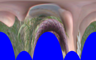
I think of this as "unrolling" the image by cutting it from the top down to the central point, then stretching it out so the central point becomes the entire top row of the output, and the two sides of the cut line are inverted to become the upper parts of the west and east sides of the output. The input corner or corners that are furthest from the central point will be on the south edges of the output.
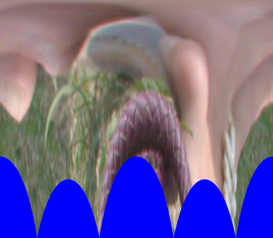
Imagine the image composited over a blue circle, such that the central point is over the circle's centre, and the radius is such that the corner of the image that is furthest from the central point is on the circumference. Then the blue circle will be distorted to the rectangular "depolar" output.
The inverse operation is -distort polar -1,0.
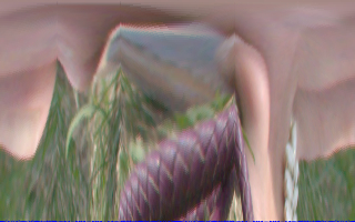
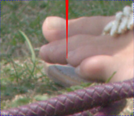
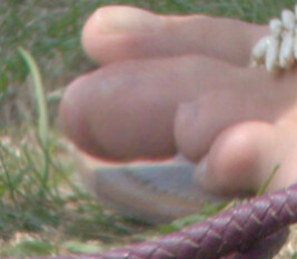
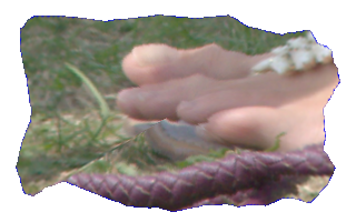
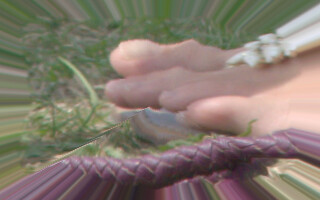
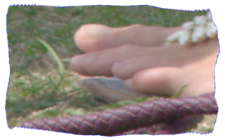
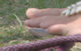
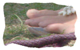
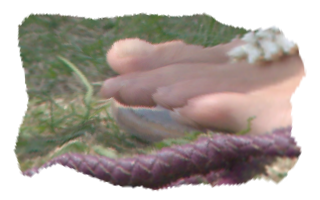
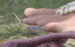
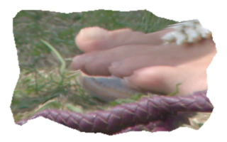
set SRC=toes.png
|

|
|
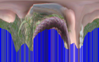
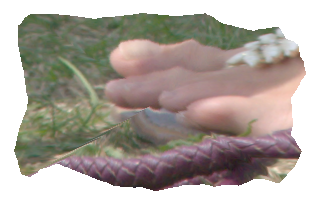
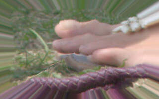
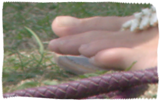
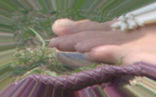
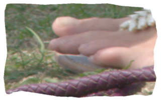
Unroll the source:
%IMG7%magick ^
  %SRC% ^
  -background Blue ^
  -virtual-pixel Background ^
  -distort depolar -1 ^
  pd_src_u.png
|

|
|
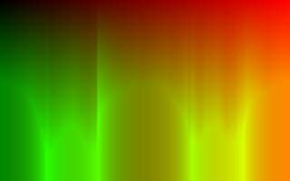
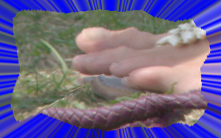
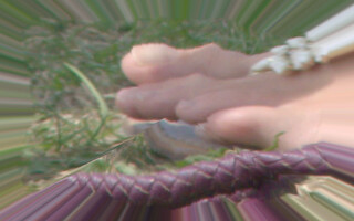
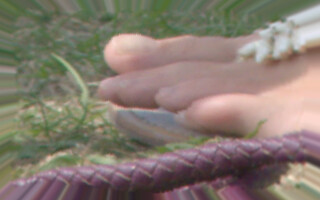
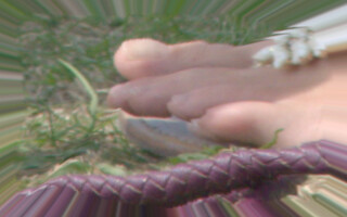
Roll it back:
%IMG7%magick ^
  pd_src_u.png ^
  -distort polar -1 ^
  pd_src_ur.png
|

|
|
Did we get back to where we started?
%IMG7%magick compare ^
  %SRC% ^
  pd_src_ur.png ^
  -metric RMSE ^
  NULL:
1411.8 (0.0215426)
|
[No image]
|
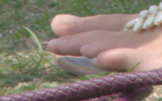
The inverse transformation is correct but the sampling is not accurate. Using Q32 HDRI makes no difference to the accuracy. To improve this, see
Supersampling below.
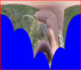
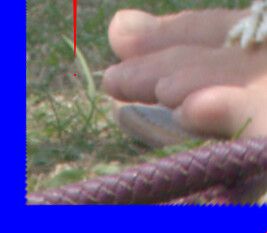
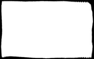
Drawing a thin red inner-border at the edges of the unrolled image helps to clarify what happens when the unrolled image is rolled up.
set IN_BORDER=( -clone 0 ^
  -alpha Transparent ^
  -shave 1x1 ^
  -alpha Off ^
  -bordercolor Red -border 1 ^
  -alpha On ^
  ) ^
  -compose Over -composite
|
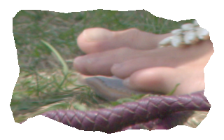
Unroll the source and draw a border:
%IMG7%magick ^
  %SRC% ^
  -background Blue ^
  -virtual-pixel Background ^
  -distort depolar -1 ^
  %IN_BORDER% ^
  pd_src_u2.png
|
|
|
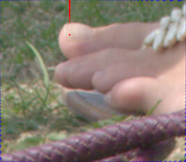
Roll it back:
%IMG7%magick ^
  pd_src_u2.png ^
  -distort polar -1 ^
  pd_src_ur2.png
|
|
The sides of the unrolled image have become a line from the central point to the north edge.
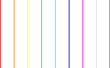
When the parameters are set as above (-1,0 *,* -180,180), x-coordinates in the unrolled image correspond to directions from the central point of the rolled image:
x-coordinate in
unrolled image |
direction in
rolled image |
| 0% (first column) |
north |
| 12.5% |
north-west |
| 25% |
west |
| 37.5% |
south-west |
| 50% |
south |
| 62.5% |
south-east |
| 75% |
east |
| 87.5% |
north-east |
| 100% (last column) |
nearly north |
The y-coordinate corresponds to the radius from the central point. A point at maximum y-coordinate, the bottom row of the unrolled image, is furthest from the central point.
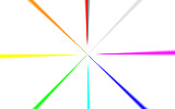
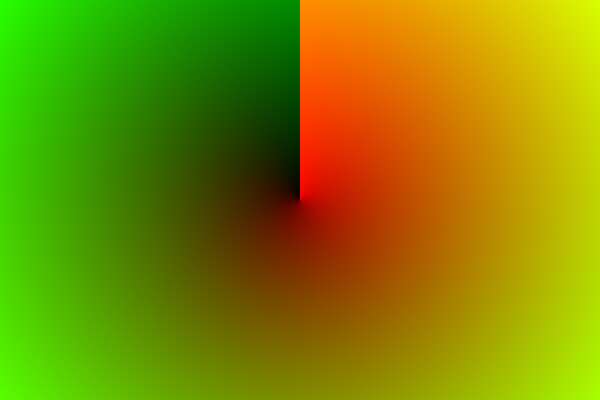
For example:
%IMG7%magick ^
  -size 160x100 xc:White ^
  -stroke #f00 -draw "line 0,0,0,99" ^
  -stroke #f80 -draw "line 20,0,20,99" ^
  -stroke #ff0 -draw "line 40,0,40,99" ^
  -stroke #0f0 -draw "line 60,0,60,99" ^
  -stroke #0ff -draw "line 80,0,80,99" ^
  -stroke #00f -draw "line 100,0,100,99" ^
  -stroke #f0f -draw "line 120,0,120,99" ^
  -stroke #ddd -draw "line 140,0,140,99" ^
  -stroke #888 -draw "line 159,0,159,99" ^
  +write pd_ex_ang.png ^
  -distort Polar -1,0 ^
  pd_ex_ang2.png
|
|
To unroll and roll an image, we can use -fx. The basic transformations are:
theta = atan2 (x,y)
rho = hypot (x,y)

x = sin (theta) * rho
y = cos (theta) * rho
The -fx code is more complex because the scales are different (in the unrolled image, the x-axis is theta in radians in the range -pi/2 to +pi/2, and the y-axis is rho from zero at the top to the semi-diagonal at the bottom), and because arithmetic is performed on image coordinates, not pixel coordinates (see
Distorting Images: Image Coordinates vs Pixel Coordinates).
First, we define a pair of environment variables for the two transformations:
set fxDep=^
  SemiDiagW = %%[fx:hypot(w,h)/(w*2)]; ^
  SemiDiagH = %%[fx:hypot(w,h)/(h*2)]; ^
  theta = pi + %%[fx:2*pi/w] * (i+0.5); ^
  rho = (j+0.5) / %%[fx:h-1]; ^
  xx = sin(theta) * SemiDiagW * rho + 0.5; ^
  yy = cos(theta) * SemiDiagH * rho + 0.5; ^
  p { xx*%%[fx:w-1] , yy*%%[fx:h-1] }

set fxPol=^
  ii = i - %%[fx:w/2 - 0.5]; ^
  jj = j - %%[fx:h/2 - 0.5]; ^
  rho = hypot (ii,jj) / %%[fx:hypot(w,h)/2]; ^
  theta = atan2 (ii,jj) + pi; ^
  xx = theta / %%[fx:2*pi] * %%[fx:w-1]; ^
  yy = rho * %%[fx:h-1]; ^
  p {xx, yy}
Now we can use those as -fx expressions to unroll an image, and roll up the result:
%IMG7%magick ^
  %SRC% ^
  -background Blue ^
  -virtual-pixel Background ^
  -fx "%fxDep%" ^
  ( +clone ^
    +write pd_fx_unr.png ^
    +delete ^
  ) ^
  -fx "%fxPol%" ^
  pd_fx_roll.png
|


|
Did we get back to where we started?
%IMG7%magick compare ^
  %SRC% ^
  pd_fx_roll.png ^
  -metric RMSE ^
  NULL:
1732.82 (0.0264411)
The round-trip was successful. For better quality, we should use
supersampling; see below.
We can also compare the unroll done by -distort depolar -1 with the unroll done by -fx:
%IMG7%magick compare ^
  pd_src_u.png ^
  pd_fx_unr.png ^
  -metric RMSE ^
  NULL:
241.335 (0.00368254)
The two methods for unrolling are practically the same.
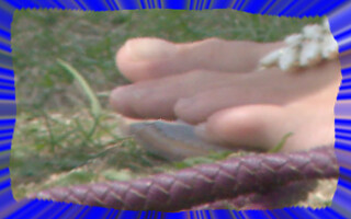
We can increase the accuracy as measured by round-trip RMSE by supersampling. An obvious mechanism for supersampling is to increase the size of input image before unrolling. After doing whatever processing we need to the unrolled image, we roll it back up and shrink it back down. For example, resizing by a factor of 2:
|
Enlarge and unroll the source:
%IMG7%magick ^
  %SRC% ^
  -resize 200%% ^
  -background Blue ^
  -virtual-pixel Background ^
  -distort depolar -1 ^
  pd_src_u3.png
|
|
|
Roll it back and shrink:
%IMG7%magick ^
  pd_src_u3.png ^
  -distort polar -1 ^
  -resize 50%% ^
  pd_src_ur3.png
|

|
|
Did we get back to where we started?
%IMG7%magick compare ^
  %SRC% ^
  pd_src_ur3.png ^
  -metric RMSE ^
  NULL:
679.895 (0.0103745)
|
[No image]
|
Supersampling x4:
|
Unroll the source:
%IMG7%magick ^
  %SRC% ^
  -resize 400%% ^
  -background Blue ^
  -virtual-pixel Background ^
  -distort depolar -1 ^
  pd_src_u4.png
|
Not shown.
|
|
Roll it back:
%IMG7%magick ^
  pd_src_u4.png ^
  -distort polar -1 ^
  -resize 25%% ^
  pd_src_ur4.png
|

|
|
Did we get back to where we started?
%IMG7%magick compare ^
  %SRC% ^
  pd_src_ur4.png ^
  -metric RMSE ^
  NULL:
328.025 (0.00500534)
|
[No image]
|
Supersampling x8:
|
Unroll the source:
%IMG7%magick ^
  %SRC% ^
  -resize 800%% ^
  -background Blue ^
  -virtual-pixel Background ^
  -distort depolar -1 ^
  pd_src_u5.png
|
Not shown.
|
|
Roll it back:
%IMG7%magick ^
  pd_src_u5.png ^
  -distort polar -1 ^
  -resize 12.5%% ^
  pd_src_ur5.png
|

|
|
Did we get back to where we started?
%IMG7%magick compare ^
  %SRC% ^
  pd_src_ur5.png ^
  -metric RMSE ^
  NULL:
259.316 (0.0039569)
|
[No image]
|
The -distort command respects a "distort:scale" option. This has a similar effect to resizing the image before distorting. It may be faster.
|
Unroll the source:
%IMG7%magick ^
  %SRC% ^
  -background Blue ^
  -virtual-pixel Background ^
  -define distort:scale=2 ^
  -distort depolar -1 ^
  pd_src_u6.png
|

|
|
Roll it back:
%IMG7%magick ^
  pd_src_u6.png ^
  -define distort:scale=0.5 ^
  -distort polar -1 ^
  pd_src_ur6.png
|

|
|
Did we get back to where we started?
%IMG7%magick compare ^
  %SRC% ^
  pd_src_ur6.png ^
  -metric RMSE ^
  NULL:
782.571 (0.0119413)
|
[No image]
|
|
Unroll the source:
%IMG7%magick ^
  %SRC% ^
  -background Blue ^
  -virtual-pixel Background ^
  -define distort:scale=4 ^
  -distort depolar -1 ^
  pd_src_u7.png
|
Not shown.
|
|
Roll it back:
%IMG7%magick ^
  pd_src_u7.png ^
  -define distort:scale=0.25 ^
  -distort polar -1 ^
  pd_src_ur7.png
|

|
|
Did we get back to where we started?
%IMG7%magick compare ^
  %SRC% ^
  pd_src_ur7.png ^
  -metric RMSE ^
  NULL:
526.079 (0.00802745)
|
[No image]
|
|
Unroll the source:
%IMG7%magick ^
  %SRC% ^
  -background Blue ^
  -virtual-pixel Background ^
  -define distort:scale=8 ^
  -distort depolar -1 ^
  pd_src_u8.png
|
Not shown.
|
|
Roll it back:
%IMG7%magick ^
  pd_src_u8.png ^
  -define distort:scale=0.125 ^
  -distort polar -1 ^
  pd_src_ur8.png
|

|
|
Did we get back to where we started?
%IMG7%magick compare ^
  %SRC% ^
  pd_src_ur8.png ^
  -metric RMSE ^
  NULL:
454.505 (0.0069353)
|
[No image]
|
Conclusions:
- For supersampling, "-resize" gives a better round-trip accuracy than the equivalent "distort:scale".
- Resizing by 100%, 200%, 400% and 800% gives a round-trip RMSE of approximately 2%, 1%, 0.5% and 0.4%.
We define the central point with an x,y coordinate-pair. The default central point is at (width/2.0,height/2.0).
|
Unroll the source:
%IMG7%magick ^
  %SRC% ^
  -background Blue ^
  -virtual-pixel Background ^
  -distort depolar -1,0,100,50 ^
  %IN_BORDER% ^
  pd_src_u_of1.png
|
|
|
Roll it back:
%IMG7%magick ^
  pd_src_u_of1.png ^
  -distort polar -1,0,100,50 ^
  pd_src_ur_of1.png
The red border has become a dot at the central point,
and a thin red line.
Some blue is evident around the edges.
|
|
|
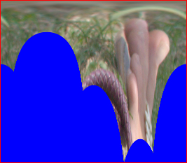
Unroll the source, with different central point:
%IMG7%magick ^
  %SRC% ^
  -background Blue ^
  -virtual-pixel Background ^
  -distort depolar -1,0,50,100 ^
  %IN_BORDER% ^
  pd_src_u_of2.png
|
|
|
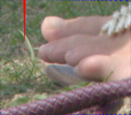
Roll it back:
%IMG7%magick ^
  pd_src_u_of2.png ^
  -distort polar -1,0,50,100 ^
  pd_src_ur_of2.png
Some blue is evident around the edges.
|
|
|
Roll it back with "wrong" central point:
%IMG7%magick ^
  pd_src_u_of2.png ^
  -distort polar -1,0,75,75 ^
  pd_src_ur_of2a.png
The real image has been linearly displaced.
|
|
In the examples above, virtual pixels are shown as blue for clarity. This also shows some problems at edges. In practice, -virtual-pixel Edge is generally preferable.
We put the above into a script
polDist.bat that takes an image, unrolls it, does some procesing, and rolls back. The processing is specfied in environment variable pdDISTORT. This must be valid IM syntax. It will operate on a single image, the unrolled image.
The default settings give no overall distortion.
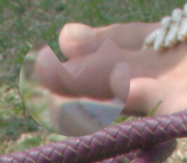
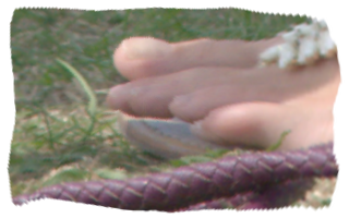
call %PICTBAT%polDist toes.png
|

|
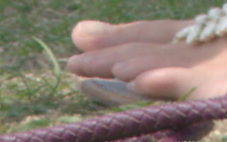
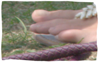
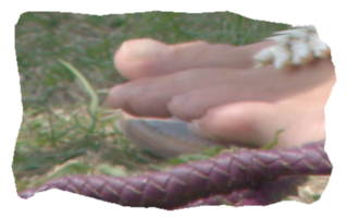
We set pdDISTORT to crop out most of the top 20% of the image and stretch it vertically. This operates on the unrolled image, so the effect is to enlarge a circular area. We offset the central point, and super-sample by a factor of 4.
set pdDISTORT=( ^
  +clone ^
  -gravity North ^
  -crop 80%%x20%% -resize 100%%x200%% ^
) -composite
call %PICTBAT%polDist toes.png 40%%%% . 4 pd_scr1.png
|
|
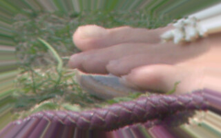
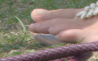
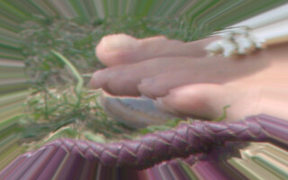
A different pdDISTORT gives a blended magnifying effect, using an absolute displacement map. This is built as the identity (undistorting) map, then the green (vertical) channel values are tweaked. Any occurrences of [ssW_2] or [ssH_2] will be substituted by the numerical values of half the super-sampled width and height.
set pdDISTORT=( ^
  +clone ^
  -sparse-color Bilinear "0,0,#000 %%[fx:w-1],0,#f00 0,%%[fx:h-1],#0f0 %%[fx:w-1],%%[fx:h-1],#ff0" ^
  -channel G -evaluate Pow 1.5 +channel ^
) -compose Distort -set option:compose:args [ssW_2]x[ssH_2] -composite
set pdDISTORT=( ^
  +clone ^
  -sparse-color Bilinear "0,0,#000 %%[fx:w-1],0,#f00 0,%%[fx:h-1],#0f0 %%[fx:w-1],%%[fx:h-1],#ff0" ^
  -channel G -evaluate Pow 1.5 +channel ^
) -compose Distort -set option:compose:args 100%%x100%% -composite
call %PICTBAT%polDist toes.png 40%%%% . 4 pd_scr2.png
|
|
If desired, pdDISTORT could start or end with +write file.ext to save intermediate results.
Housekeeping:
set pdDISTORT=
|
Create the identity absolute displacement map.
set WW=600
set HH=400

set SP_COLS=0,0,#000,^
%%[fx:w-1],0,#f00,^
0,%%[fx:h-1],#0f0,^
%%[fx:w-1],%%[fx:h-1],#ff0

%IMG7%magick ^
  -size %WW%x%HH% xc: ^
  -sparse-color Bilinear "%SP_COLS%" ^
  pd_id_abs.png
|
|
|
Create the unrolling absolute displacement map.
%IMG7%magick ^
  pd_id_abs.png ^
  -resize 400%% ^
  -distort depolar -1 ^
  -resize "%WW%x%HH%^!" ^
  pd_unr_abs.png
|
|
To create the rolling displacement map, we could use one of two methods: "-distort polar" the identity absolute displacement map, or invert the unrolling map with
process module invdispmap followed by a blur-fill.
|
Method 1.
%IMG7%magick ^
  pd_id_abs.png ^
  -resize 400%% ^
  -distort polar -1 ^
  -resize "%WW%x%HH%^!" ^
  pd_r1_abs.png
|
|
|
Method 2.
%IM7DEV%magick ^
  pd_unr_abs.png ^
  -resize 400%% ^
  -process invdispmap ^
  -resize "%WW%x%HH%^!" ^
  pd_r2_abs.png
There are many holes.
|
|
The invdispmap method results in many holes, including at the vertical line northwards from the central point. Blur-fill will create inaccuracy, so we won't consider this method further.
As they are inverses of each other, displacing the unrolling map by the rolling map should result in the identity map, more or less.
%IMG7%magick ^
  pd_unr_abs.png ^
  pd_r1_abs.png ^
  -compose Distort ^
    -set option:compose:args 100%%x100%% ^
    -composite ^
  pd_id_abs.png ^
  -metric RMSE ^
  -format %%[distortion] ^
  -compare ^
  info:
0.00189501
Yes, it is quite accurate.
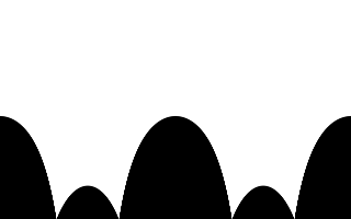
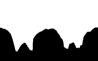
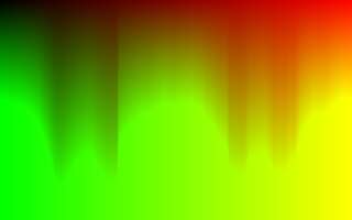
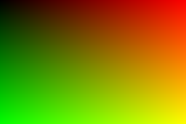
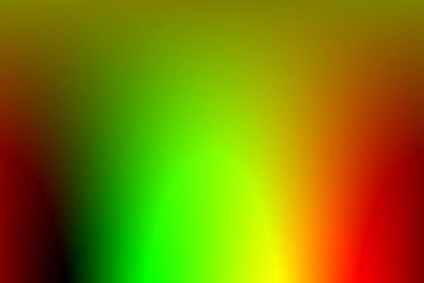
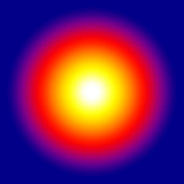
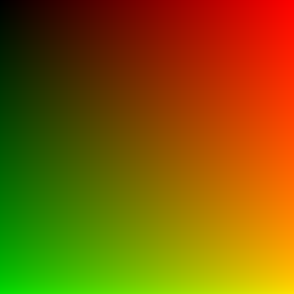
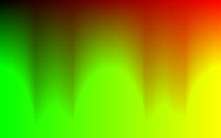
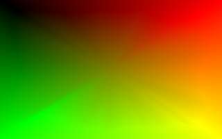
We can create rectangular gradients and roll them up, making radial gradients.
%IMG7%magick ^
  xc:#fff xc:#ff0 xc:#f80 xc:#f00 xc:#808 xc:#008 ^
  -append +repage ^
  -resize "600x600^!" ^
  -distort polar 0 ^
  pd_radgrad1.png
|
|
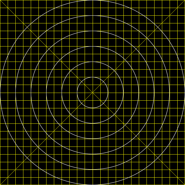
If we have an image that represents texture of a sphere, such as a planet, we can map the texture so it wraps around the sphere, as if seen from an infinite distance.
|
Create a texture for a planet.
set PL_SRC=pd_plan_tex.png

call %PICTBAT%grid ^
  601 601 24 24 1 yellow black yellow %PL_SRC%

%IMG7%magick ^
  %PL_SRC% ^
  -stroke White -fill None ^
  -draw "circle 300,300 300,350" ^
  -draw "circle 300,300 300,400" ^
  -draw "circle 300,300 300,450" ^
  -draw "circle 300,300 300,500" ^
  -draw "circle 300,300 300,550" ^
  -draw "circle 300,300 300,600" ^
  %PL_SRC%
|
|
|
Make an absolute displacement map for the unrolled texture.
set PL_SC=0,0,#000,^
%%[fx:w-1],0,#f00,^
0,%%[fx:h-1],#0f0,^
%%[fx:w-1],%%[fx:h-1],#ff0

%IMG7%magick ^
  %PL_SRC% ^
  -sparse-color bilinear "%PL_SC%" ^
  -channel G ^
  -function ArcSin 2,0,2,0 ^
  +channel ^
  pd_plan_dm.png
|
|
|
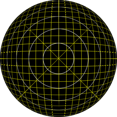
Unroll, displace, and roll.
%IMG7%magick ^
  %PL_SRC% ^
  -background Blue ^
  -virtual-pixel None ^
  -distort depolar 0 ^
  pd_plan_dm.png ^
  -compose Distort ^
    -set option:compose:args 100%%x100%% ^
    -composite ^
  -distort polar 0 ^
  -resize 63.66198%% ^
  pd_plan.png
The resize (100 * 2/pi) makes the scale in the centre of the result
the same as in the input texture image, %PL_SRC%.
|
|
For another example of this distortion, see
Fractal noise.
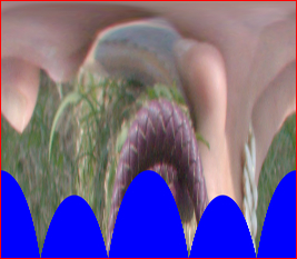
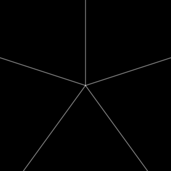
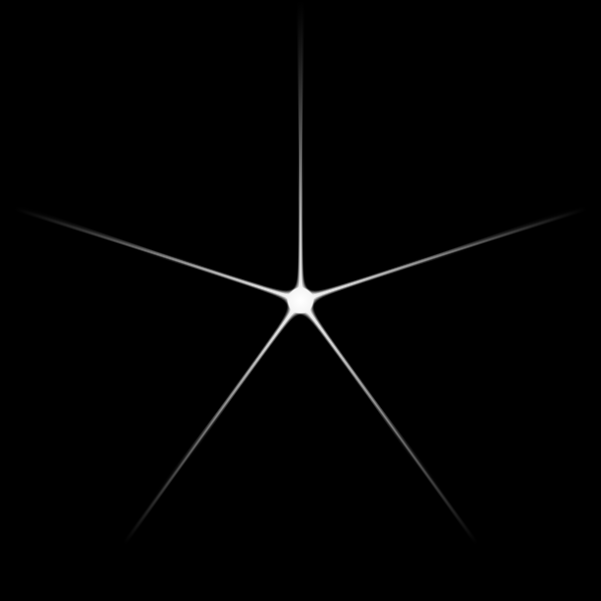
Unrolling an image smears image pixels horizontally across the unrolled image. More smearing occurs at the top than the bottom. Rolling it back would de-smear the image, but if we displace pixels downwards before we roll, they will remain somewhat smeared. This effect can create pointed stars.
|
Create a basic star with radius RAD and NUM_PTS points.
set ST_SRC=pd_star_src.png

set RAD=300
set NUM_PTS=5

set /A DIAM=2*%RAD%+1
set /A NUMm1=%NUM_PTS%-1

%IMG7%magick ^
  -size %DIAM%x%DIAM% ^
  xc:None ^
  -stroke White ^
  -draw "line %RAD%,%RAD% %RAD%,0" ^
  -duplicate %NUMm1% ^
  -distort SRT 1,%%[fx:360*t/n] ^
  -background Black ^
  -layers Merge ^
  -blur 0x1 ^
  -channel RGB -auto-level ^
  %ST_SRC%
|
|
|
Unroll the basic star;
move it down by 20 pixels;
apply linear gradient;
roll it back.
%IMG7%magick ^
  %ST_SRC% ^
  -virtual-pixel Edge ^
  -distort depolar 0 ^
  -distort SRT 0,-20,1,0,0,0 ^
  -auto-level ^
  -level 5%%,50%% ^
  ( +clone ^
    -sparse-color bilinear "0,0,White 0,%%[fx:h-1],Black" ^
  ) ^
  -compose Multiply -composite ^
  -distort polar 0 ^
  pd_star_1.png
The points may extend to the edge of the image.
|
|
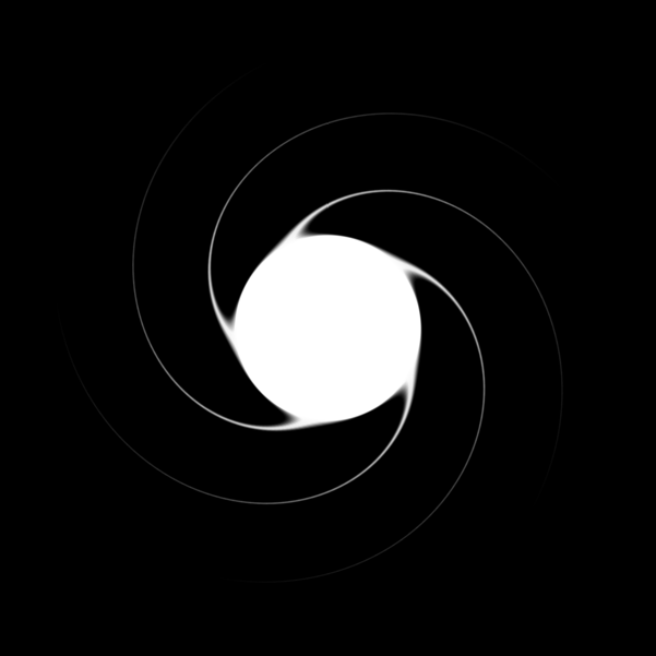
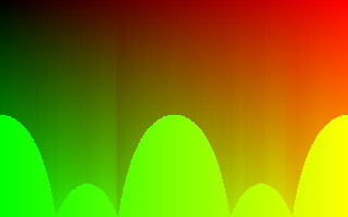
If we distort the unrolled image with a relative displacement map that varies with height, we create a catherine wheel.
|
Make a relative displacement map for the unrolled texture,
with varying horizontal component and constant vertical component.
set CW_SC=0,0,rgb(0%%,49%%,0%%),^
%%[fx:w-1],0,rgb(0%%,49%%,0%%),^
0,%%[fx:h-1],rgb(80%%,49%%,0%%),^
%%[fx:w-1],%%[fx:h-1],rgb(80%%,49%%,0%%)

%IMG7%magick ^
  %PL_SRC% ^
  -sparse-color bilinear "%CW_SC%" ^
  -channel G ^
  -function ArcSin 2,0,2,0 ^
  +channel ^
  pd_cw_dm.png
|

|
|
Unroll the basic star;
displace by the map;
apply linear gradient;
roll it back;
mask with a circle.
%IMG7%magick ^
  %ST_SRC% ^
  -virtual-pixel Edge ^
  -distort depolar 0 ^
  -auto-level ^
  -level 5%%,50%% ^
  ( +clone ^
    -sparse-color bilinear "0,0,White 0,%%[fx:h-1],Black" ^
  ) ^
  -compose Multiply -composite ^
  pd_cw_dm.png ^
  -virtual-pixel HorizontalTileEdge ^
  -compose Displace ^
    -set option:compose:args 100%%x100%% ^
    -composite ^
  -virtual-pixel Edge ^
  -distort polar 0 ^
  ( -size %DIAM%x%DIAM% ^
    xc:Black ^
    -fill White ^
    -draw "circle %RAD%,%RAD% %RAD%,0" ^
  ) ^
  -alpha off ^
  -compose Multiply -composite ^
  pd_cw_1.png
|
|
|
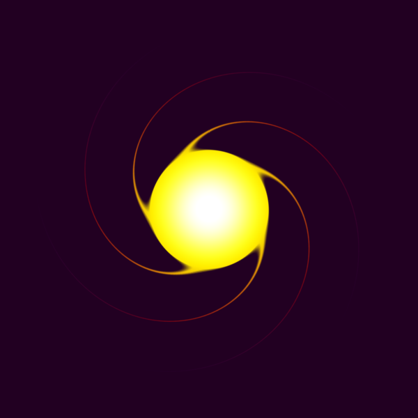
Use this as a mask to a radial gradient.
%IMG7%magick ^
  pd_radgrad1.png ^
  pd_cw_1.png ^
  -alpha off ^
  -compose CopyOpacity -composite ^
  -background #202 ^
  -compose Over -layers flatten ^
  pd_cw_2.png
|
|
We can make a star field. First, we take the star image and make the background transparent, then make 49 copies. The input image is centred at 300,300 so the SRT moves that to the origin, then scales and rotates by random amounts, and moves to a random position. The SRT operates on all images, with different calculations for each. The 50 images are then merged over a dark blue background.
The -seed is for reproducibility in regression testing.
set SF_SRT=300,300,^
%%[fx:0.01+0.6*rand()],%%[fx:360*rand()],^
%%[fx:600*rand()],%%[fx:400*rand()]

%IMG7%magick ^
  -seed 1234 ^
  pd_star_1.png ^
  ( +clone ) ^
  -alpha off ^
  -compose CopyOpacity -composite ^
  -duplicate 49 ^
  +distort SRT "%SF_SRT%" ^
  -background #004 ^
  -compose Over -layers merge ^
  -fuzz 1%% -trim +repage ^
  pd_starfield.png
|

|
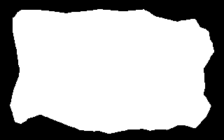
We can unroll a shape, and use that to create a displacement map with techniques shown in
Straightening horizons. This is then used to distort an image so it exactly fits the white shape. The process re-frames the image, so instead of fitting in a rectangular frame, it fits in an arbitrary frame.
For example, taking an image from the
Islands page:
|
is_easy_mainland.png
|
|
This image has a slight problem. From the centre, not all boundary points are visible: there is a slight occlusion at the bottom-left. (FUTURE: It would be useful if we could easily find a central point that maximised the visibility of edge points.)
for /F "usebackq" %%L in (`%IMG7%magick identify ^
  -format "MNLD_WW=%%w\nMNLD_HH=%%h\n" ^
  is_easy_mainland.png`) do set %%L

echo MNLD_WW=%MNLD_WW%  MNLD_HH=%MNLD_HH%
MNLD_WW=320 MNLD_HH=200
We resize toes.png to the dimensions of is_easy_mainland.png. Instead, we could resize the mainland mask to the toes image. In general, we can't simply resize displacement maps, as the values depend on the aspect ratio.
%IMG7%magick ^
  toes.png ^
  -resize "%MNLD_WW%x%MNLD_HH%^!" ^
  pd_toes_res.png
|

|
|
Unroll it.
%IMG7%magick ^
  pd_toes_res.png ^
  -background Blue ^
  -virtual-pixel Background ^
  -distort depolar -1 ^
  pd_toes_res_u.png
|
|
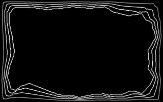
We create two absolute displacement maps. The first ("vdbi") takes the unrolled image and enlarges it to fill the rectangle. The second ("vdm") takes the result, and shrinks it to the boundary of the white area. Then we combine the two maps.
Filename conventions: *_mnld: mainland; *_vdbi: vertical displacement from circle to border inverted; *_vdm: vertical displacement from circle to map.
pd_map_f.png is a displacement map for transforming an unrolled rectangular image to an unrolled image that, when rolled, fits inside the white area of is_easy_mainland.png.
The invclut process has precision limited by the width of the image. If the image is only 200 pixels wide, the precision is only 0.5%. Precision can be improved by supersampling. Applying supersampling to just invclut gives a little improvement. For a significant improvement, supersampling should be applied to the entire process, especially to (un)rolling.
We might want an animation between the undistorted image and one that displaces to the boundary of the white area. For this, we need the process to handle proportional displacements. It must also create the appropriate mask for the proportion.
The method creates the unrolled proportional mask. From this, we easily get the rolled proportional mask, and a forwards proportional vertical displacement map (pd_map_fp.png) and its inverse (pd_map_rp.png).
How do we get the unrolled proportional mask? We take the unrolled mainland and displace it by vdbi. This "subtracts" the border displacement, so represents the full displacement from the undistorted image to the mask. We resize this down to the appropriate percentage, and "add" back the border displacement.
|
Displace the unrolled mainland by the vdbi disp map:
%IMG7%magick ^
  pd_mnld-1.png -set colorspace sRGB ^
  pd_vdbi_2.png ^
  -compose Distort ^
    -set option:compose:args 100%%x100%% ^
    -composite ^
  pd_mnld_only.png
|
|
|
Squash it down to a percentage:
set SQUASH_PC=50

%IMG7%magick ^
  pd_mnld_only.png ^
  ( -clone 0 -fill White -colorize 100 ) ^
  ( -clone 0 -resize 100%%x%SQUASH_PC%%% ) ^
  -delete 0 ^
  -gravity South -composite ^
  pd_mo_pr.png
When the percentage is so small it resizes to zero height, the command will fail.
|
|
|
Displace this back, with vdb:
%IMG7%magick ^
  pd_mo_pr.png -set colorspace sRGB ^
  pd_vdb_2.png ^
  -compose Distort ^
    -set option:compose:args 100%%x100%% ^
    -composite ^
  pd_mnld_pr.png
|
|
|
Roll this up:
%IMG7%magick ^
  pd_mnld_pr.png ^
  -distort polar -1 ^
  pd_mnld_pr_r.png
This is the mask for the proportional displacement.
|
|
|
From mnld_pr, make displacement map
and add red and blue channels:
%IM7DEV%magick ^
  pd_mnld_pr.png ^
  -rotate -90 ^
  -colorspace sRGB ^
  -process 'cumulhisto norm' ^
  -rotate 90 ^
  ( -clone 0 ^
    -sparse-color bilinear "%GRAD_RED%" ) ^
  ( -clone 0 ^
    -fill #000 -colorize 100 ) ^
  -swap 0,1 ^
  -combine ^
  pd_vdmp.png
|
|
|
Combine the vdbi and vdmp absolute disp maps:
%IMG7%magick ^
  pd_vdbi_2.png ^
  pd_vdmp.png ^
  -compose Distort ^
    -set option:compose:args 100%%x100%% ^
    -composite ^
  pd_map_fp.png
|
|
|
Make the inverse of this:
%IM7DEV%magick ^
  pd_map_fp.png ^
  ( +clone ^
    -rotate -90 ^
    -process 'invclut' ^
    -rotate 90 ^
  ) ^
  -compose CopyGreen -composite ^
  pd_map_rp.png
|
|
pd_map_fp.png and pd_map_rp.png are the forwards and reverse dispacement maps, for unrolled images, between the rectanglar border and a proportion of the distance to the mask.
We will
apply, below, these proportional displacement maps and the mask.
We can transform an image such as pd_toes_res.png with one of two methods.
Method 1:
- Unroll pd_toes_res.png (already done, above, as pd_toes_res_u.png).
- Distort that with pd_map_f.png.
- Roll that up.
Method 2:
- Combine three maps: the unrolling map, pd_map_f.png and the rolling map.
- Use the combined map to distort pd_toes_res.png.
Both methods create repeated, "smeared", pixels outside the required area. These can be masked out.
Here is method 1:
|
Distort the unrolled toes image with this map:
%IMG7%magick ^
  pd_toes_res_u.png ^
  pd_map_f.png ^
  -compose Distort ^
    -set option:compose:args 100%%x100%% ^
    -composite ^
  pd_u_dist.png
|
|
|
Roll this up:
%IMG7%magick ^
  pd_u_dist.png ^
  -distort polar -1 ^
  pd_u_dist_r.png
|
|
|
Mask the result:
%IMG7%magick ^
  pd_u_dist_r.png ^
  is_easy_mainland.png ^
  -alpha off ^
  -compose CopyOpacity -composite ^
  pd_u_dist_r_m.png
|
|
Here is method 2:
|
Combine three maps:
set SP_COLS=0,0,#000,^
%%[fx:w-1],0,#f00,^
0,%%[fx:h-1],#0f0,^
%%[fx:w-1],%%[fx:h-1],#ff0

%IMG7%magick ^
  pd_map_f.png ^
  ( -clone 0 ^
    -sparse-color Bilinear "%SP_COLS%" ^
    -distort depolar -1 ^
  ) ^
  +swap ^
  -compose Distort ^
  -set option:compose:args 100%%x100%% ^
  -composite ^
  ( -clone 0 ^
    -sparse-color Bilinear "%SP_COLS%" ^
    -distort polar -1 ^
  ) ^
  -composite ^
  pd_map_f_x3.png
|
|
|
Distort toes with this map:
%IMG7%magick ^
  pd_toes_res.png ^
  pd_map_f_x3.png ^
  -compose Distort ^
    -set option:compose:args 100%%x100%% ^
    -composite ^
  pd_res_dist.png
|
|
|
Mask the result:
%IMG7%magick ^
  pd_res_dist.png ^
  is_easy_mainland.png ^
  -alpha off ^
  -compose CopyOpacity -composite ^
  pd_res_dist_m.png
|
|
Both methods show a displacement discontinuity from the centre towards the bottom-left corner, caused by the occlusion in is_easy_mainland.png. We can distort with a blurred version of the map.
|
Distort and mask:
%IMG7%magick ^
  pd_toes_res.png ^
  ( pd_map_f_x3.png ^
    -blur 0x5 ^
  ) ^
  -compose Distort ^
    -set option:compose:args 100%%x100%% ^
    -composite ^
  is_easy_mainland.png ^
  -alpha off ^
  -compose CopyOpacity -composite ^
  pd_res_dist_m2.png
|
|
Above, we made
proportional displacement maps and a mask. Now, we apply them, using method 1.
|
Distort the unrolled toes image with the proportional map
and roll it up:
%IMG7%magick ^
  pd_toes_res_u.png ^
  pd_map_fp.png ^
  -compose Distort ^
    -set option:compose:args 100%%x100%% ^
    -composite ^
  +write pd_u_dist_pr_u.png ^
  -distort polar -1 ^
  pd_u_dist_pr.png
|
|
|
Mask the result:
%IMG7%magick ^
  pd_u_dist_pr.png ^
  pd_mnld_pr_r.png ^
  -alpha off ^
  -compose CopyOpacity -composite ^
  pd_u_dist_pr_m.png
|
|
|
Undistort the result by using the reverse map,
and roll it up:
%IMG7%magick ^
  pd_u_dist_pr_u.png ^
  pd_map_rp.png ^
  -compose Distort ^
    -set option:compose:args 100%%x100%% ^
    -composite ^
  -distort polar -1 ^
  pd_u_dist_pr_ur.png
|

|
|
Compare the round-trip with the source:
%IMG7%magick compare ^
  pd_u_dist_pr_ur.png ^
  pd_toes_res.png ^
  -metric RMSE ^
  NULL:
2127.97 (0.0324707)
|
[No image]
|
This is fairly accurate.
We put the above into a script,
r2shPol.bat, that takes a rectangular image and a mask with white shape on black background, and distorts the rectangle to the shape, or the reverse. Optionally it takes the coordinates of the central point and a factor for supersampling and a proportion for the effect and forwards/reverse. Optionally, it also writes the absolute displacement map that operates on the unrolled image.
|
Forwards transformation,
distorting from the rectangle to the shape.
call %PICTBAT%r2shPol ^
  pd_toes_res.png ^
  is_easy_mainland.png ^
  pd_scf.png
|
|
|
Reverse that result
back to the rectangle.
call %PICTBAT%r2shPol ^
  pd_scf.png ^
  is_easy_mainland.png ^
  pd_scr.png . . r
|

|
|
Is the round-trip accurate?
%IMG7%magick compare ^
  pd_toes_res.png ^
  pd_scr.png ^
  -metric RMSE ^
  NULL:
1135.09 (0.0173203)
Fairly accurate, but not great.
|
[No image]
|
Repeat the test, with supersampling. The displacement maps are large, and not shown here.
|
Forwards transformation,
distorting from the rectangle to the shape.
set r2spSUP_SAMP=4
call %PICTBAT%r2shPol ^
  pd_toes_res.png ^
  is_easy_mainland.png ^
  pd_scfs.png
|
|
|
Reverse that result
back to the rectangle.
call %PICTBAT%r2shPol ^
  pd_scfs.png ^
  is_easy_mainland.png ^
  pd_scrs.png . . r

set r2spSUP_SAMP=
|

|
|
Is the round-trip accurate?
%IMG7%magick compare ^
  pd_toes_res.png ^
  pd_scrs.png ^
  -metric RMSE ^
  NULL:
517.258 (0.00789285)
Yes, the result is accurate.
|
[No image]
|
Looking closely at the last result, we see the discontinuity from the centre towards the bottom-left corner. We choose a different central point to avoid this problem.
|
Forwards transformation,
distorting from the rectangle to the shape.
set r2spSUP_SAMP=4
set r2spDISP_MAP=pd_temp.miff

call %PICTBAT%r2shPol ^
  pd_toes_res.png ^
  is_easy_mainland.png ^
  pd_scfsc.png 40%%%% 40%%%%
|

|
|
Reverse that result
back to the rectangle.
set r2spSUP_SAMP=2

call %PICTBAT%r2shPol ^
  pd_scfsc.png ^
  is_easy_mainland.png ^
  pd_scrsc.png 40%%%% 40%%%% r

set r2spSUP_SAMP=
|

|
|
Is the round-trip accurate?
%IMG7%magick compare ^
  pd_toes_res.png ^
  pd_scrsc.png ^
  -metric RMSE ^
  NULL:
649.941 (0.00991746)
Yes, the result is accurate.
|
[No image]
|
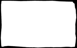
We can exercise the script in the forwards and reverse directions at different percentages of effect, showing:
- the distorted image, not masked down, so we have repeated pixels;
- the mask that is made;
- the distorted image, masked down to remove the repeated pixels;
- version (1) distorted back to a rectangle;
- the RMSE comparison between (4) and the input image.
set r2spSUP_SAMP=

for /L %%i in (0,25,100) do (

  set r2spPREFIX=pd_dist_%%i

  call %PICTBAT%r2shPol ^
    pd_toes_res.png ^
    is_easy_mainland.png ^
    pd_dist_%%i.png 40%%%% 40%%%% . %%i

  if ERRORLEVEL 1 exit /B 1

  set r2spPREFIX=

  call %PICTBAT%r2shPol ^
    pd_toes_res.png ^
    is_easy_mainland.png ^
    pd_dist_m_%%i.png 40%%%% 40%%%% . %%i 1

  if ERRORLEVEL 1 exit /B 1

  set r2spPREFIX=pd_dist_r_%%i

  call %PICTBAT%r2shPol ^
    pd_dist_%%i.png ^
    is_easy_mainland.png ^
    pd_dist_r_%%i.png 40%%%% 40%%%% r %%i

  if ERRORLEVEL 1 exit /B 1

  for /F "usebackq tokens=2 delims=() " %%C in (`%IMG7%magick compare ^
    -metric RMSE pd_toes_res.png pd_dist_r_%%i.png ^
    NULL: 2^>^&1`) do echo %%C >pd_dist_%%i.lis
)

if ERRORLEVEL 1 exit /B 1

set r2spSUP_SAMP=
Percentage
effect |
pd_dist_*.png
Distorted, not masked-down |
pd_dist_*_mask.miff
Mask |
pd_dist_m_*.png
Distorted, masked-down |
pd_dist_r_*.png
Distorted then undistorted |
RMSE |
| 0% |

|

|

|
|
0 |
| 25% |
|
|
|

|
0.019235 |
| 50% |
|
|
|
|
0.0197479 |
| 75% |
|
|
|

|
0.0201902 |
| 100% |
|
|
|

|
0.0206817 |
We repeat the test with super-sampling.
set r2spSUP_SAMP=4

for /L %%i in (0,25,100) do (

  set r2spPREFIX=pd_dist4_%%i

  call %PICTBAT%r2shPol ^
    pd_toes_res.png ^
    is_easy_mainland.png ^
    pd_dist4_%%i.png 40%%%% 40%%%% . %%i

  set r2spPREFIX=

  call %PICTBAT%r2shPol ^
    pd_toes_res.png ^
    is_easy_mainland.png ^
    pd_dist4_m_%%i.png 40%%%% 40%%%% . %%i 1

  set r2spPREFIX=pd_dist4_r_%%i

  call %PICTBAT%r2shPol ^
    pd_dist4_%%i.png ^
    is_easy_mainland.png ^
    pd_dist4_r_%%i.png 40%%%% 40%%%% r %%i

  for /F "usebackq tokens=2 delims=() " %%C in (`%IMG7%magick compare ^
    -metric RMSE pd_toes_res.png pd_dist4_r_%%i.png ^
    NULL: 2^>^&1`) do echo %%C >pd_dist4_%%i.lis
)

set r2spSUP_SAMP=
Percentage
effect |
pd_dist4_*.png
Distorted, not masked-down |
pd_dist4_*_mask.miff
Mask |
pd_dist4_m_*.png
Distorted, masked-down |
pd_dist4_r_*.png
Distorted then undistorted |
RMSE |
| 0% |

|

|

|

|
0 |
| 25% |

|
|
|
|
0.00600189 |
| 50% |
|
|
|

|
0.00641149 |
| 75% |
|
|
|

|
0.00723653 |
| 100% |
|
|
|

|
0.00863518 |
With supersampling, the edges of the masks are far cleaner, and the RMSE has improved: halved or better.
By finding the edges of the masks and superimposing these edges, we can gauge the accuracy of the proportions.
%IMG7%magick ^
  pd_dist4_25_mask_sup.miff ^
  pd_dist4_50_mask_sup.miff ^
  pd_dist4_75_mask_sup.miff ^
  pd_dist4_100_mask_sup.miff ^
  -morphology edgein diamond:1 ^
  -channel RGB -auto-level ^
  -background Black ^
  -compose Lighten -layers merge ^
  -auto-level ^
  -resize 25%% ^
  -channel RGB -auto-level +channel ^
  pd_supmask.png
They look fine.
|
|
|
A cuter method for superimposing masks:
%IMG7%magick ^
  pd_dist4_25_mask_sup.miff ^
  pd_dist4_50_mask_sup.miff ^
  pd_dist4_75_mask_sup.miff ^
  pd_dist4_100_mask_sup.miff ^
  -background Black ^
  -compose Plus -layers merge ^
  -resize 25%% ^
  -channel RGB -auto-level +channel ^
  -set colorspace RGB -colorspace sRGB ^
  pd_supmask2.png
They look fine.
|
|
The script
r2shPol.bat could be optimised for animation sequences, so work that is constant between frames is not repeated.
The script r2shPol.bat can transform a rectangular image to an arbitrary shape, or transform in the opposite direction. We can use this to transform from one arbitrary shape to another, by calling the script twice:
- Transform from the first shape to a rectangle.
- Transform from the rectangle to the second shape.
For efficiency and quality, we should upsample before running the scripts and downsample after, instead of using the script's internal mechanism.
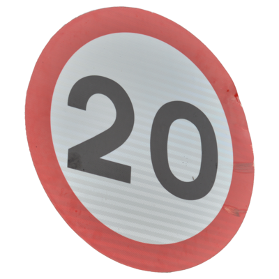
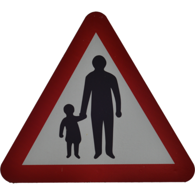
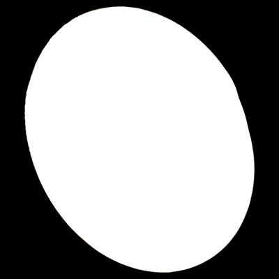
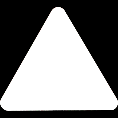
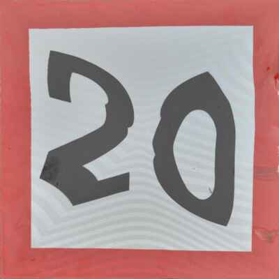
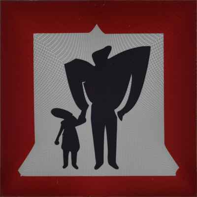
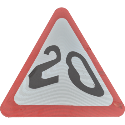
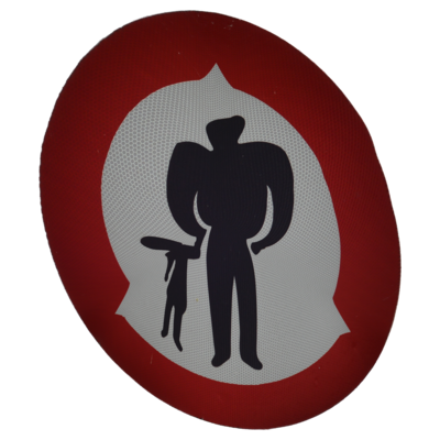
We show this with a pair of images. The road signs were isolated with
GrowCut segmentation. Each will be distorted to the shape of the other. Operations will be done on large images (3000x3000 pixels), without super-sampling.
set SRC_DIR=%PICTLIB%20150805\

set SRC1=%SRC_DIR%AGA_2499_rnd2.tiff
set SRC2=%SRC_DIR%AGA_2505_tri2.tiff
Images will be resized for the web.
set WEB_RESIZE=-resize 400x400 -quality 40
FUTURE: The process could be extended so that, as well as distorting pixel inside one shape to fit inside another shape, we also distort pixels outside the shape.
FUTURE: If we can use the same central point for the two shapes, then we can take a short cut. Instead of four distortions (shape to circle, circle to rectangle, rectangle to circle, circle to second shape), we can skip the middle two distortions. We distort from shape to circle, then from circle to the second shape. But can we go directly from one shape to another? Probably not easily: unless the second mask is entirely within the first, the "Displace the unrolled mainland by the vdbi disp map" operation would go off the bottom of the image. Maybe we could tweak vdbi and vdb, by adding or sbtracting 0.5, to put the "base" at y=50%, then use gravity center. They would need to be divided by 2.
Another use for unrolled images is to find a
Nearest coastal point.
We don't need to keep the miff files, so delete them.
rem del pd_*.miff
For convenience, .bat scripts are also available in a single zip file. See
Zipped BAT files.
rem Given image %1,
rem unrolls it, does some procesing, and rolls back.
rem %2, %3 coords of central point  [default center of %1]
rem   Each coord may be suffixed with "%", for percentage of width or height.
rem %4 factor for supersamping [1]
rem %5 optional output file.
rem
rem The processing is given in environment variable pdDISTORT.
@rem
@rem Also uses:
@rem   pdIM if set, uses this insead of %IMG7% for location of IM programs.
@rem
@rem
@rem Updated:
@rem   22-August-2022 Upgraded for IM v7.
@rem


@if "%1"=="" findstr /B "rem @rem" %~f0 & exit /B 1

@setlocal

@call echoOffSave

call %PICTBAT%setInOut %1 pd

if not "%5"=="" set OUTFILE=%5

if "%pdIM%"=="" set pdIM=%IMG7%

set CENT_X=%2
set CENT_Y=%3
set SUP_SAMP=%4

if "%CENT_X%"=="." set CENT_X=
if "%CENT_Y%"=="." set CENT_Y=

set BLANK_CENT=0
if "%CENT_X%"=="" if "%CENT_Y%"=="" set BLANK_CENT=1

if "%CENT_X%"=="" set CENT_X=50%%
if "%CENT_Y%"=="" set CENT_Y=50%%

echo CENT_X=%CENT_X%  CENT_Y=%CENT_Y%

set X_SUFFIX=%CENT_X:~-1%
if "%X_SUFFIX%"=="%%" (
  set nX=%CENT_X:~0,-1%
  set X_MULT=w/100
) else (
  set nX=%CENT_X%
  set X_MULT=1
)

set Y_SUFFIX=%CENT_Y:~-1%
if "%Y_SUFFIX%"=="%%" (
  set nY=%CENT_Y:~0,-1%
  set Y_MULT=h/100
) else (
  set nY=%CENT_Y%
  set Y_MULT=1
)

if "%SUP_SAMP%"=="." set SUP_SAMP=
if "%SUP_SAMP%"=="" set SUP_SAMP=1

for /F "usebackq" %%L in (`%pdIM%magick identify ^
  -format "WW=%%w\nHH=%%h\nnX=%%[fx:%nX%*%SUP_SAMP%*%X_MULT%]\nnY=%%[fx:%nY%*%SUP_SAMP%*%Y_MULT%]"
  %INFILE%`) do set %%L

echo WW=%WW%  HH=%HH%  nX=%nX%  nY=%nY%


set sCENT=,%nX%,%nY%
if %BLANK_CENT%==1 set sCENT=

if %SUP_SAMP%==1 (
  set sSUP_UP=
  set sSUP_DN=
) else (
  for /F "usebackq tokens=*" %%L in (`%pdIM%magick identify ^
    -format "sSUP_UP=-resize %%[fx:100*%SUP_SAMP%]%%%%"
    xc:`) do set %%L

  set sSUP_DN=-resize "%WW%x%HH%^^^!"
)

echo sSUP_UP=%sSUP_UP%  sSUP_DN=%sSUP_DN%

for /F "usebackq" %%L in (`%pdIM%magick identify ^
  -format "ssW_2=%%[fx:w*%SUP_SAMP%/2]\nssH_2=%%[fx:h*%SUP_SAMP%/2]"
  %INFILE%`) do set %%L

set pdd=
if not defined pdDISTORT goto skip_pdd
  set pdd=%pdDISTORT:[ssW_2]=!ssW_2!%
  set pdd=%pdd:[ssH_2]=!ssH_2!%
:skip_pdd

%pdIM%magick ^
  %INFILE% ^
  %sSUP_UP% ^
  -distort depolar -1,0%sCENT% ^
  %pdd% ^
  -distort polar -1,0%sCENT% ^
  %sSUP_DN% ^
  %OUTFILE%

if ERRORLEVEL 1 exit /B 1

call echoRestore

@endlocal & set pdOUTFILE=%OUTFILE%
@rem Given image %1
@rem and same-size mask %2, white shape on black background,
@rem distorts image into white shape with polar displacement.
@rem
@rem Optional arguments:
@rem   %3 output filename [*_r2sp.*]
@rem   %4, %5 coords of central point  [default center of %1]
@rem        Each coord may be suffixed with "%", for percentage of width or height.
@rem        Default: centre of image.
@rem   %6 reverse transformation (shape -> rectangle)
@rem        f=forwards, r=reverse [f]
@rem   %7 proportion towards mask displacement (0 to 100) [100]
@rem   %8 mask-down (make transparent where mask is black)
@rem        0=no, 1=yes, [0]
@rem
@rem Also uses:
@rem   r2spSUP_SAMP Factor for supersampling [default 1].
@rem   r2spBLUR_MAP Operation to blur map, eg "-blur 0x5" [No blur]
@rem   r2spPREFIX prefix for temporary files
@rem   [[ r2spDISP_MAP filename for output absolute displacement map [no file] ]]
@rem
@rem Updated:
@rem   22-August-2022 Upgraded for IM v7.
@rem

@if "%2"=="" findstr /B "rem @rem" %~f0 & exit /B 1

@setlocal enabledelayedexpansion

@call echoOffSave

call %PICTBAT%setInOut %1 r2sp

set MASK_FILE=%2

if "%r2spDISP_MAP%"=="" set r2spDISP_MAP=%sioCODE%_mnld.png

if "%r2spIM%"=="" set r2spIM=%IMG7%

set OUTF=%3
if "%OUTF%"=="." set OUTF=
if "%OUTF%"=="" set OUTF=%OUTFILE%
set OUTFILE=%OUTF%

set PREFIX=%r2spPREFIX%
if "%PREFIX%"=="" set PREFIX=r2sp

set CENT_X=%4
set CENT_Y=%5

if "%CENT_X%"=="." set CENT_X=
if "%CENT_Y%"=="." set CENT_Y=

set BLANK_CENT=0
if "%CENT_X%"=="" if "%CENT_Y%"=="" set BLANK_CENT=1

if "%CENT_X%"=="" set CENT_X=50%%
if "%CENT_Y%"=="" set CENT_Y=50%%

set X_SUFFIX=%CENT_X:~-1%
if "%X_SUFFIX%"=="%%" (
  set nX=%CENT_X:~0,-1%
  set X_MULT=w/100
) else (
  set nX=%CENT_X%
  set X_MULT=1
)

set Y_SUFFIX=%CENT_Y:~-1%
if "%Y_SUFFIX%"=="%%" (
  set nY=%CENT_Y:~0,-1%
  set Y_MULT=h/100
) else (
  set nY=%CENT_Y%
  set Y_MULT=1
)

set FOR_REV=%6
if "%FOR_REV%"=="." set FOR_REV=
if "%FOR_REV%"=="" set FOR_REV=f
if not "%FOR_REV%"=="f" if not "%FOR_REV%"=="r" (
  echo FOR_REV is "%FOR_REV%" but must be one of "f" or "r".
  exit /B 1
)


set PROP=%7
if "%PROP%"=="." set PROP=
if "%PROP%"=="" set PROP=100

set MASK_DN=%8
if "%MASK_DN%"=="." set MASK_DN=
if "%MASK_DN%"=="" set MASK_DN=0

set SUP_SAMP=%r2spSUP_SAMP%
if "%SUP_SAMP%"=="." set SUP_SAMP=
if "%SUP_SAMP%"=="" set SUP_SAMP=1

for /F "usebackq" %%L in (`%r2spIM%magick identify ^
  -format "WW=%%w\nHH=%%h\nW_SS=%%[fx:w*%SUP_SAMP%]\nH_SS=%%[fx:h*%SUP_SAMP%]\nnX=%%[fx:%nX%*%SUP_SAMP%*%X_MULT%]\nnY=%%[fx:%nY%*%SUP_SAMP%*%Y_MULT%]"
  %INFILE%`) do set %%L

echo WW=%WW%  HH=%HH%  W_SS=%W_SS%  H_SS=%H_SS%  nX=%nX%  nY=%nY%

if %BLANK_CENT%==1 (
  set sUNROLL=-distort depolar "-1,0"
  set sROLL=-distort polar "-1,0"
) else (
  set sUNROLL=-distort depolar "-1,0,%nX%,%nY%"
  set sROLL=-distort polar "-1,0,%nX%,%nY%"
)

if %SUP_SAMP%==1 (
  set sSUP_UP=
  set sSUP_DN=
) else (
  for /F "usebackq tokens=*" %%L in (`%r2spIM%magick identify ^
    -format "sSUP_UP=-resize %%[fx:100*%SUP_SAMP%]%%%%"
    xc:`) do set %%L

  set sSUP_UP=-resize "%W_SS%x%H_SS%^^^!"
  set sSUP_DN=-resize "%WW%x%HH%^^^!"
)

echo sSUP_UP=%sSUP_UP%  sSUP_DN=%sSUP_DN%

set GRAD_RED=0,0,Black,%%[fx:w-1],0,White

if %FOR_REV%==f (
  set INV_NUM=1
) else (
  set INV_NUM=0
)

set ID_ABS_MAP=0,0,#000,^
%%[fx:w-1],0,#f00,^
0,%%[fx:h-1],#0f0,^
%%[fx:w-1],%%[fx:h-1],#ff0

:: Vertical Displacement Mask/Background (Inverse)
rem FIXME: we no longer need _vdm or _vdmi
%IM7DEV%magick ^
  %MASK_FILE% ^
  %sSUP_UP% ^
  +depth ^
  +write %PREFIX%_mask_sup.miff ^
  ( +clone ^
    -sparse-color Bilinear "%ID_ABS_MAP%" ^
    +write %PREFIX%_iam.miff ^
    +delete ^
  ) ^
  -background Black ^
  -virtual-pixel Background ^
  ( +clone ^
    %sUNROLL% ^
    +write %PREFIX%_mnld_unr.miff ^
    -rotate -90 ^
    -process 'cumulhisto norm' ^
    ( +clone ^
      -rotate 90 ^
      +write %PREFIX%_vdm.miff ^
      +delete ^
    ) ^
    -process 'invclut' ^
    -rotate 90 ^
    +write %PREFIX%_vdmi.miff ^
    +delete ^
  ) ^
  ( +clone ^
    -fill White -colorize 100 ^
    %sUNROLL% ^
    -rotate -90 ^
    -process 'cumulhisto norm' ^
    ( +clone ^
      -rotate 90 ^
      +write %PREFIX%_vdb.miff ^
      +delete ^
    ) ^
    -process 'invclut' ^
    -rotate 90 ^
    +write %PREFIX%_vdbi.miff ^
    +delete ^
  ) ^
  NULL:

if ERRORLEVEL 1 exit /B 1

%r2spIM%magick ^
  %PREFIX%_iam.miff ^
  ( +clone ^
    %PREFIX%_vdm.miff ^
    -compose CopyGreen -composite ^
    +write %PREFIX%_vdm.miff ^
    +delete ^
  ) ^
  ( +clone ^
    %PREFIX%_vdmi.miff ^
    -compose CopyGreen -composite ^
    +write %PREFIX%_vdmi.miff ^
    +delete ^
  ) ^
  ( +clone ^
    %PREFIX%_vdb.miff ^
    -compose CopyGreen -composite ^
    +write %PREFIX%_vdb.miff ^
    +delete ^
  ) ^
  ( +clone ^
    %PREFIX%_vdbi.miff ^
    -compose CopyGreen -composite ^
    +write %PREFIX%_vdbi.miff ^
    +delete ^
  ) ^
  NULL:

if ERRORLEVEL 1 exit /B 1

set DIST_MAP=-compose Distort -set option:compose:args 100%%x100%% -composite


for /F "usebackq" %%L in (`%r2spIM%magick identify ^
  -format "PROP_OK=%%[fx:int(%H_SS%*%PROP%/100)>0?1:0]"
  xc:`) do set %%L

set PROP_OK=%PROP_OK%

:: Proportional

rem _mo_pr isn't needed?

rem If PROP_OK==0, _mnld_pr.miff and both masks should be white.

if %PROP_OK%==0 (

  %r2spIM%magick ^
    -size %W_SS%x%H_SS% xc:White ^
    +write %PREFIX%_mo_pr.miff ^
    +write %PREFIX%_mnld_pr.miff ^
    +write %PREFIX%_mask_sup.miff ^
    +delete ^
    -size %WW%x%HH% xc:White ^
    %PREFIX%_mask.miff

  %r2spIM%magick ^
    %INFILE% ^
    %OUTFILE%

  rem FIXME: Do we also need identity maps?

  goto finished
)

%r2spIM%magick ^
  %PREFIX%_mnld_unr.miff ^
  %PREFIX%_vdbi.miff ^
  %DIST_MAP% ^
  ^( -clone 0 -fill White -colorize 100 ^) ^
  ^( -clone 0 -resize 100%%x%PROP%%% ^) ^
  -delete 0 ^
  -gravity South -compose Over -composite ^
  +write %PREFIX%_mo_pr.miff ^
  %PREFIX%_vdb.miff ^
  %DIST_MAP% ^
  +write %PREFIX%_mnld_pr.miff ^
  %sROLL% ^
  +write %PREFIX%_mask_sup.miff ^
  %sSUP_DN% ^
  %PREFIX%_mask.miff

if ERRORLEVEL 1 exit /B 1


%IM7DEV%magick ^
  %PREFIX%_mnld_pr.miff ^
  -rotate -90 ^
  -process 'cumulhisto norm' ^
  -rotate 90 ^
  ( -clone 0 ^
    -sparse-color bilinear "%GRAD_RED%" ) ^
  ( -clone 0 ^
    -fill #000 -colorize 100 ) ^
  -swap 0,1 ^
  -combine ^
  %PREFIX%_vdmp.miff

%IM7DEV%magick ^
  %PREFIX%_vdbi.miff ^
  %PREFIX%_vdmp.miff ^
  %DIST_MAP% ^
  %r2spBLUR_MAP% ^
  +write %PREFIX%_map_fp.miff ^
  ( +clone ^
    -rotate -90 ^
    -process 'invclut' ^
    -rotate 90 ^
  ) ^
  -compose CopyGreen -composite ^
  %PREFIX%_map_rp.miff


if %MASK_DN%==0 (
  set sMASK=
) else (
  set sMASK=%PREFIX%_mask_sup.miff -compose CopyOpacity -composite
)

%r2spIM%magick ^
  %INFILE% ^
  %sSUP_UP% ^
  %sUNROLL% ^
  %PREFIX%_map_%FOR_REV%p.miff ^
  %DIST_MAP% ^
  %sROLL% ^
  %sMASK% ^
  %sSUP_DN% ^
  %OUTFILE%

if ERRORLEVEL 1 exit /B 1


:finished

call echoRestore

@endlocal & set r2shOUTFILE=%OUTFILE%
@rem Given image %1
@rem and mask %2, white shape on black background,
@rem distorts image into white shape with horizontal or polar displacement.
@rem
@rem Optional arguments:
@rem   %3 proportion towards displacement (0 to 100) [100]
@rem   %4 reverse transformation (shape -> rectangle)
@rem        f=forwards, r=reverse (r is buggy; FIXME) [f]
@rem   %5 output filename [*_s2sp.*]
@rem   %6 mask-down (make transparent where mask is black)
@rem        1=yes, 0=no [1]
@rem   %7 filename for output relative displacement map [no file] (NYI)
@rem
@rem Also uses:
@rem   s2spSUP_SAMP Factor for supersampling [default 1].
@rem
@rem Updated:
@rem   22-August-2022 Upgraded for IM v7.
@rem
@rem FIXME: also need method of specifying central coord.
@rem        (If neither specified, leave blank in "-distort".)
@rem

@if "%2"=="" findstr /B "rem @rem" %~f0 & exit /B 1

@setlocal enabledelayedexpansion

@call echoOffSave

call %PICTBAT%setInOut %1 s2sp

set MASK_FILE=%2

set PROP_DIST=%3
if "%PROP_DIST%"=="." set PROP_DIST=
if "%PROP_DIST%"=="" set PROP_DIST=100

set FOR_REV=%4
if "%FOR_REV%"=="." set FOR_REV=
if "%FOR_REV%"=="" set FOR_REV=f

set OUTF=%5
if "%OUTF%"=="." set OUTF=
if "%OUTF%"=="" set OUTF=%OUTFILE%
set OUTFILE=%OUTF%

set MASK_DOWN=%6
if "%MASK_DOWN%"=="." set MASK_DOWN=
if "%MASK_DOWN%"=="" set MASK_DOWN=1

set OUT_MAP=%7
if "%OUT_MAP%"=="." set OUT_MAP=
if "%OUT_MAP%"=="" set OUT_MAP=

set SUP_SAMP=%s2spSUP_SAMP%
if "%SUP_SAMP%"=="" set SUP_SAMP=1


for /F "usebackq" %%L in (`%IMG7%magick identify ^
  -precision 15 ^
  -format "Wm1=%%[fx:%SUP_SAMP%*w-1]\nHm1=%%[fx:%SUP_SAMP%*h-1]\nSUP_SAMPinvPc=%%[fx:100/%SUP_SAMP%]\nSUP_SAMPinv=%%[fx:1/%SUP_SAMP%]" ^
  %INFILE%`) do set %%L

set sUNROLL=-virtual-pixel Background ^
  -distort depolar -1

set sROLL=-distort polar -1

set sCOMPMATH=-compose Mathematics ^
  -define compose:args=0,-0.5,0.5,0.5 ^
  -composite

if "%PROP_DIST%"=="100" (
  set sPROP=
) else (
  for /F "usebackq" %%L in (`%IMG7%magick identify ^
    -format="%%[fx:100-%PROP_DIST%]" ^
    xc:`) do set sPROP=-fill gray^(50%%^) -colorize %%L
)

if /I "%FOR_REV%"=="r" (
  set sREVERSE=-rotate -90 -process invclut -rotate 90

  set sREVERSE=-rotate -90 ^
+write z0.png ^
    mpr:IDENT ^
    -compose Mathematics -define compose:args=0,1,1,-0.5 -composite ^
+write z1.png ^
    -process invclut ^
    mpr:IDENT ^
    -compose Mathematics -define compose:args=0,-1,1,0.5 -composite ^
+write z2.png ^
    -rotate 90

) else (
  set sREVERSE=
)

if "%MASK_DOWN%"=="1" (
  set sMASK_DOWN=mpr:MASK -alpha off -compose CopyOpacity -composite
) else (
  set sMASK_DOWN=
)

%IM7DEV%magick ^
  -define distort:scale=%SUP_SAMP% ^
  %INFILE% ^
  %sUNROLL% ^
  ( %MASK_FILE% -write mpr:MASK ) ^
  +depth ^
  ( -clone 1 ^
    ( -clone 0 ^
      -fill White -colorize 100 ^
      -background Black ^
      %sUNROLL% ^
      -rotate -90 ^
      -process 'cumulhisto norm' ^
      -process 'invclut' ^
      ( +clone ^
        -sparse-color Bilinear ^
          "0,0 Black %%[fx:w-1],0 White" ^
        -write mpr:IDENT ^
      ) ^
      %sCOMPMATH% ^
+write x0.png ^
      mpr:IDENT ^
      +swap ^
      -compose Displace ^
      -set option:compose:args %Hm1%x0 -composite ^
    ) ^
    ( -clone 0 ^
+write x1b.png ^
      -background Black ^
      %sUNROLL% ^
      -rotate -90 ^
      -process 'cumulhisto norm' ^
+write x1a.png ^
      mpr:IDENT ^
      %sCOMPMATH% ^
+write x1.png ^
    ) ^
    -delete 0 ^
-write info: ^
    -compose Displace ^
    -set option:compose:args %Hm1%x0 -composite ^
    mpr:IDENT ^
    %sCOMPMATH% ^
    -rotate 90 ^
    %sPROP% ^
    %sREVERSE% ^
+write x2.png ^
  ) ^
  -delete 1 ^
  -compose Displace ^
  -set option:compose:args 0x%Hm1% -composite ^
  -define distort:scale=%SUP_SAMPinv% ^
-virtual-pixel None ^
  -distort polar -1 ^
  %sMASK_DOWN% ^
  -depth 16 ^
  %OUTFILE%

rem IM bug? if %OUTFILE% is .png, we get corrupt file, unless we have "-depth 16".


call echoRestore

@endlocal & set sh2shOUTFILE=%OUTFILE%
All images on this page were created by the commands shown, using:
%IMG7%magick -version
Version: ImageMagick 7.1.1-15 Q16-HDRI x64 a0a5f3d:20230730 https://imagemagick.org
Copyright: (C) 1999 ImageMagick Studio LLC
License: https://imagemagick.org/script/license.php
Features: Cipher DPC HDRI OpenCL OpenMP(2.0)
Delegates (built-in): bzlib cairo freetype gslib heic jng jp2 jpeg jxl lcms lqr lzma openexr pangocairo png ps raqm raw rsvg tiff webp xml zip zlib
Compiler: Visual Studio 2022 (193532217)
%IM7DEV%magick -version
Version: ImageMagick 7.1.1-13 (Beta) Q32-HDRI x86_64 a8de149e1:20230703 https://imagemagick.org
Copyright: (C) 1999 ImageMagick Studio LLC
License: https://imagemagick.org/script/license.php
Features: Cipher DPC HDRI Modules OpenCL OpenMP(4.5)
Delegates (built-in): bzlib cairo fftw fontconfig freetype heic jbig jng jpeg lcms ltdl lzma pangocairo png raqm raw rsvg tiff webp wmf x xml zip zlib
Compiler: gcc (11.3)
To improve internet download speeds, some images may have been automatically converted (by ImageMagick, of course) from PNG or TIFF or MIFF to JPG.
Source file for this web page is poldist.h1. To re-create this web page, run "procH1 poldist", then manually delete pd_*.miff.
This page, including the images, is my copyright. Anyone is permitted to use or adapt any of the code, scripts or images for any purpose, including commercial use.
Anyone is permitted to re-publish this page, but only for non-commercial use.
Anyone is permitted to link to this page, including for commercial use.
Page version v1.0 23-July-2015.
Page created 28-Sep-2023 21:39:14.
Copyright © 2023 Alan Gibson.