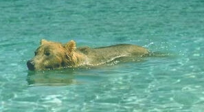
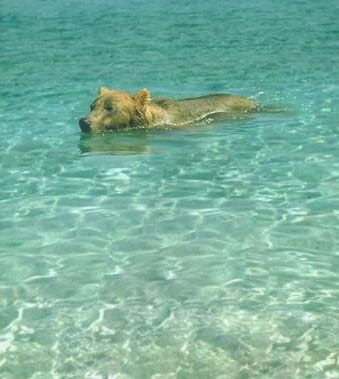
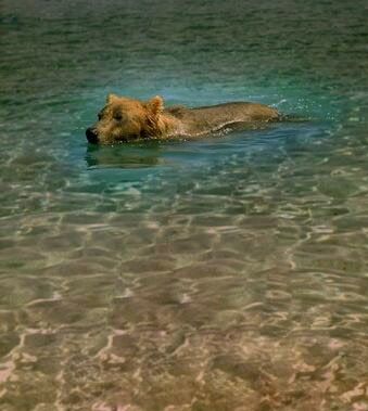
set BEAR=perez_bear.jpg
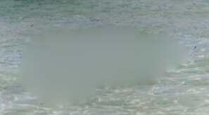
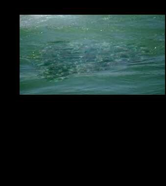
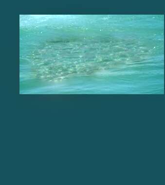
set WATER=perez_water.jpg
Poisson image editing, and related techniques.
This page describes the Poisson image editing technique for blending two or more images. I implement the basic Poisson process as a fairly simple script, relaxFillMS.bat. However, this can be used in a number of ways.
This page is concerned with images, not mathematics. (I am a picture maker, not a mathematician.) Interested readers may feast on the mathematics in the references.
CAUTION: In v1.0 of this page (23-October-2014), slope and divergence images were offset so zero was represented by pixel values of 50%.
However, this caused problems due to the Fifty percent issue, so now zero slopes are represented by pixel values of 0%, and negative values are common, and HDRI should be used.
After I wrote v2 of this page in 2017, IM has implemented operations "-compose seamless-blend -composite" and "-compose saliency-blend -composite". See Seamless-blend and Saliency-blend below.
This page draws heavily on:
Other related papers, though not directly considered on this page:
This page uses a version of IM assumed to be HDRI.
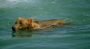
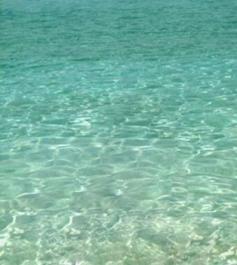
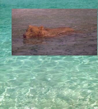
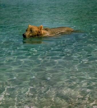
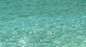
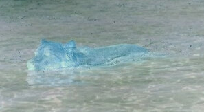
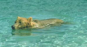
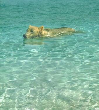
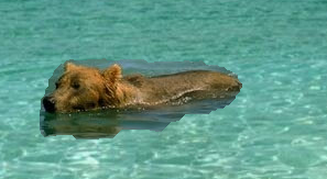
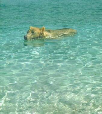
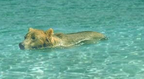
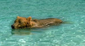
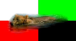
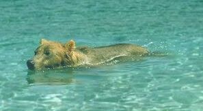
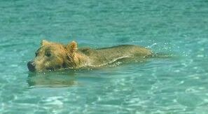
We use two images from the following paper:
set BEAR=perez_bear.jpg |
|
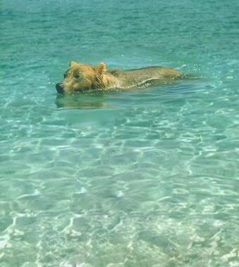
set WATER=perez_water.jpg |
|
The images are not my copyright. I think the animal is a bear, but I could be wrong.
The goal is to cut-out the bear and paste it over the water. The water in the foreground bear photo is generally darker than the required background.
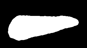
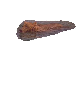
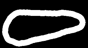
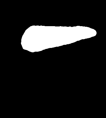
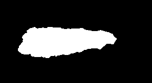
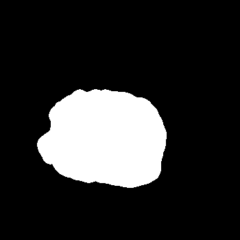
For the cut-out, we will use a mask that I made with Gimp, roughly following the example in the Pérez paper. It is white where we want the bear image; otherwise black.
set MASK=bear_mask.png |
|
We will offset the bear image:
set sOFFSET=+40+30

set sGEOM=-geometry %sOFFSET%
Get the dimensions of the original bear image:
for /F "usebackq" %%L in (`%IMG7%magick identify ^
  -format "WW=%%w\nHH=%%h\nWm1=%%[fx:w-1]\nHm1=%%[fx:h-1]" ^
  %BEAR%`) do set %%L

echo WW=%WW% HH=%HH%
WW=297 HH=163
For this page, we will try to use OpenCL, to do some processing on the GPU.
set MAGICK_OCL_DEVICE=true
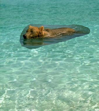
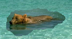
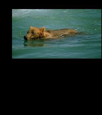
We can simply cut out the bear and composite over the water.
%IMG7%magick ^
  %WATER% ^
  ( %BEAR% %MASK% -alpha off ^
    -compose CopyOpacity -composite ^
  ) ^
  %sGEOM% ^
  -compose Over -composite ^
  spm_simpmont.jpg
|
|
The boundary between the images is obvious. We want a seamless boundary. We could blur the boundary, but the difference in the water would still be obvious.
The basic method in the Pérez paper is called "Poisson interpolation", "seamless boundary by Poisson image editing" or even "seamless boundary by Poisson equation with Dirichlet boundary conditions". For short, I call it simply "Poisson pasting".
The simple version of the method (with no explicit "guidance vector field") adds an adjustment (or "correction") image to the foreground bear image before compositing it over the water background. The adjustment image has pixels corresponding to the mask boundary exactly equal to the water image minus the bear image. Hence, when added to the bear image, those pixels will be equal to the water background.
The pixels in the adjustment image outside the mask boundary won't be used so we don't care what values they have. The pixels inside the mask boundary do matter. Values should change smoothly, interpolating between values at the boundary. The smoother they change, the better the result. Put it another way: we should smooth the pixels of the adjustment image, and keep smoothing until they no longer change. This is exactly what relaxFillMS.bat does. (See Filling holes: relaxation.)
|
Calculate background minus foreground.
%IMG7%magick ^
  %WATER% ^
  %BEAR% ^
  %sGEOM% ^
  -compose Mathematics ^
    -define compose:args=0,-0.5,0.5,0.5 ^
    -composite ^
  -crop %WW%x%HH%%sOFFSET% +repage ^
  +depth ^
  +write spm_minus.png ^
  ( %MASK% -negate ) ^
  -alpha off -compose CopyOpacity -composite ^
  spm_minus_mskd.png
|

|
|
Fill the hole by relaxation. call %PICTBAT%relaxFillMS ^ spm_minus_mskd.png . spm_add1.png |
|
|
Add the result to the bear image.
%IMG7%magick ^
  %BEAR% ^
  spm_add1.png ^
  -compose Mathematics ^
    -define compose:args=0,2,1,-1 ^
    -composite ^
  +depth ^
  +write spm_bear_adj.png ^
  %MASK% -alpha off ^
  -compose CopyOpacity -composite ^
  %WATER% ^
  +swap ^
  %sGEOM% ^
  -compose Over -composite ^
  spm_s2.png
|
|
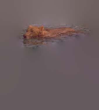
The result is good. We have the bear's reflection in the water, and the water's colour is taken from the correct image. Note that the water has lightened, but so has the bear. If we want to prevent the bear from becoming lightened, see Inner Dirichlet boundary below.
We can express the pixels that fill the hole as:
fill_pixels = bear + relax (water - bear)
At the boundary:
relax (water - bear) = water - bear
Hence, at the boundary:
fill_pixels = bear + water - bear
            = water
ASIDE
Instead of relaxFillMS.bat, we could use blurFill.bat. But this creates a discontinuity at the centre. For this example, the discontinuity is a roughly horizontal line that coincides with the base of the bear, so the problem it creates isn't visible.
call %PICTBAT%blurFill ^ spm_minus_mskd.png . spm_blr_add.png |
|
ASIDE 2
For the two mathematics composites, we could use compose:args=0,-1,1,0.5 and compose:args=0,1,1,-0.5 respectively. But if we don't use HDRI, this can clip the first result. The parameters used above have the same effect but ensure we have no clipping (at the expense of one bit of precision).
Above, we have adjusted the bear image to match the required background water. This has visibly lightened the bear's fur. Instead, we can adjust the water to match the bear.
%IMG7%magick ^
  %WATER% ^
  %BEAR% ^
  %sGEOM% ^
  -compose Mathematics ^
    -define compose:args=0,0.5,-0.5,0.5 ^
    -composite ^
  +depth ^
  +write spm_minus_r.png ^
  -alpha transparent ^
  ( %MASK%  -alpha off ) ^
  %sGEOM% ^
  -compose CopyOpacity -composite ^
  spm_minus_mskd_r.png
|
|
call %PICTBAT%relaxFillMS ^ spm_minus_mskd_r.png . ^ spm_add1_r.png 1e-6 1000 |
|
%IMG7%magick ^
  %WATER% ^
  spm_add1_r.png ^
  -compose Mathematics ^
    -define compose:args=0,2,1,-1 ^
    -composite ^
  +depth ^
  +write spm_bear_adj_r.png ^
  ( %MASK% -negate ) -alpha off ^
  %sGEOM% ^
  -set option:compose:outside-overlay false ^
  -compose CopyOpacity -composite ^
  %BEAR% ^
  %sGEOM% ^
  -compose DstOver -composite ^
  +depth ^
  spm_s2_r.png
|

|
So we can paste a foreground to a background with seamless boundary, either by adjusting the foreground or background. Of course, we could blend the two results.
The code above has used a boundary as exactly specified by a mask. Instead, a mask could define a range of possible boundaries, eg by describing a ring 20 pixels thick. Code could then find the darkest path around the ring, and we use that as the actual boundary.
%IMG7%magick ^ %MASK% ^ -alpha off ^ -morphology EdgeOut disk:20 ^ spm_ring_mask.png |
|
We use shapeDp.bat to find the darkest path in the difference between the images, around this ring. (See Awkward boundaries with dark paths.) This needs two input images and the ring mask, all the same size.
%IMG7%magick ^ %WATER% ^ -crop %WW%x%HH%%sOFFSET% +repage ^ spm_back_crp.png |
|
set sdpBLUR_SIG=0 set sdpMASK_FILE=spm_dp_mask.png call %PICTBAT%shapeDp ^ spm_back_crp.png %BEAR% spm_ring_mask.png |
|
shapeDp.bat outputs the second image composited over the first, via a calculated mask. We use that calculated mask.
set MASK2=spm_dp_mask.png

%IMG7%magick ^
  %WATER% ^
  %BEAR% ^
  %sGEOM% ^
  -compose Mathematics ^
    -define compose:args=0,-0.5,0.5,0.5 ^
    -composite ^
  -crop %WW%x%HH%%sOFFSET% +repage ^
  +depth ^
  +write spm_minus_rng.png ^
  ( %MASK2% -negate ) ^
  -alpha off ^
  -compose CopyOpacity -composite ^
  spm_minus_mskd_rng.png
|
|
call %PICTBAT%relaxFillMS ^ spm_minus_mskd_rng.png . spm_add1_rng.png |
|
%IMG7%magick ^
  %BEAR% ^
  spm_add1_rng.png ^
  -compose Mathematics ^
    -define compose:args=0,2,1,-1 ^
    -composite ^
  +depth ^
  +write spm_bear_adj_rng.png ^
  %MASK2% -alpha off ^
  -compose CopyOpacity -composite ^
  %WATER% ^
  +swap ^
  %sGEOM% ^
  -compose Over -composite ^
  +depth ^
  spm_s2_rng.png
|
|
The only noticable difference is that the water around the bear seems calmer. This is simply because the boundary is larger.
We implement the above in the script poissonPaste.bat. For simplicity, it requires the two input images and the mask to be the same size, with no offsets.
The script will adjust part of the second input image to match the first at the mask boundary. Using the mask, it then cuts out the second image and composites that over the first.
(Thus, for the common case where we adjust part of a small image to paste over a larger image, the relaxFillMS.bat wastes time blurring a large area that will be overwritten. The script could be optimised, eg by trimming the mask. Or we could have a wrapper that finds the trim of the mask, crops all three images to that, calls poissonPaste.bat, and finally reassembles the pieces.)
In this example, we extend the bear and mask to be the same size as the water.
%IMG7%magick ^
  %WATER% ^
  +depth ^
  -fill Black -colorize 100 ^
  ( -clone 0 ^
    %BEAR% ^
    %sGEOM% ^
    -compose Over -composite ^
    +write spm_bear_ext.png ^
    +delete ^
  ) ^
  ( -clone 0 ^
    %MASK% ^
    %sGEOM% ^
    -compose Over -composite ^
    +write spm_mask_ext.png ^
    +delete ^
  ) ^
  NULL:
|
|
We can paste the bear over the water, or the water over the bear. The second image is adjusted to match the first, the "under" image, at the boundary and pasted over it.
|
Poisson-paste the bear over the water: call %PICTBAT%poissonPaste ^ %WATER% spm_bear_ext.png spm_mask_ext.png ^ spm_pp_out1.png |
|
|
Poisson-paste the water over the bear: call %PICTBAT%poissonPaste ^ spm_bear_ext.png %WATER% spm_mask_ext.png ^ spm_pp_out2.png |
|
In the next two examples, we negate the effect of the mask. As before, the second image is adjusted to match the first and pasted over it. But the adjustment and pasting is where the mask is black, instead of white.
|
Poisson-paste the bear under the water: call %PICTBAT%poissonPaste ^ %WATER% spm_bear_ext.png spm_mask_ext.png ^ spm_pp_out3.png 1 |
|
|
Poisson-paste the water under the bear: call %PICTBAT%poissonPaste ^ spm_bear_ext.png %WATER% spm_mask_ext.png ^ spm_pp_out4.png 1 |
|
An improved boundary for the Poisson pasting (relaxFillMs.bat) can be found by isolating the bear from its background.
Theorem: A 3-D object with a constant colour, illuminated by white light, appears in a photograph to have varying lightness, somewhat varying saturation (or chroma), but constant hue.
Corollary: if we want to segment a photograph by objects, the hue channel is all we need.
In real life, objects rarely have exactly constant colour. And they are illuminated not merely by the main light source but also by light reflected by other objects, and this reflected light will be coloured. This is particularly evident when a low-saturation (grayish) object is close to a high-saturation object (eg bright red). The gray object easily picks up red light from the reflected red object.
And objects that have very low saturation often have widely varying hues, eg a gray object may have adjacent pixels that are sRGB(50.001%,50%,50%) and sRGB(50%,50%,50.001%). This happens at the bear's nose, which is nearly black.
And reducing an image to just hues can cause objects that are clearly distinct to merge into each other.
But it is often a useful first approximation.
Here, we set the Lightness of all pixels to 50%. We could set all Chroma to 100%, but this gives false colours to pixels at the nose, so we set very low Chroma to zero, other Chroma to 100%, with a short ramp between them.
%IMG7%magick ^ %BEAR% ^ -colorspace HCL ^ -channel 1 -level 3,5%% ^ -channel 2 -evaluate set 50%% ^ +channel ^ -colorspace sRGB ^ spm_hue.png |
|
We want just two colours. In general, when we want just (N) colours, using "-colors N" doesn't work well because many pixels we would want in in a particular group actually fall into the other. By using "-colors N+x", virtually all the pixels allocated to one of the groups will be in the correct group. If N+x is too large, we fragment the natural groups too much that the next step won't work. N+2 often works well, when N is small.
%IMG7%magick ^ spm_hue.png ^ +dither -colors 4 ^ spm_hue_4.png |
|
The sea has essentially two colours. Where the water is tilted up by a wave towards the camera, we see the colour of the water, which is somewhat green. Where the water is tilted away, the far side of a wave, we can't see into the water and instead see reflected light from the sky, which is more blue.
The sea also has a heavily distorted reflection and refraction of the bear. When reduced to four colours, a couple of small shapes have the bear's colour.
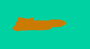
The script connCompLimArea.bat removes very small components (here, those that are less than 0.1% of the total image area).
call %PICTBAT%connCompLimArea ^ spm_hue_4.png spm_hue_4a.png 0.1c |
|
The script connCompLimNum.bat here limits the image to two components, mapping the other pixels to the colours of those two components. We have successfully lassooed the bear. Starting from the bear surrounded by water, we have found an outline for the bear.
call %PICTBAT%connCompLimNum ^ spm_hue_4a.png spm_hue_4a2.png 2 |
|
(An alternative method for simplifying spm_hue_4.png is: find the unique colours in the four edges, remap the image to these; any pixels that have changed were a different colour to all edge pixels.)
Change the colours so we have a white background and black object.
%IMG7%magick ^ spm_hue_4a2.png ^ -fill White ^ -draw "color 0,0 floodfill" ^ -fill Black +opaque White ^ spm_hue_bw.png |
|
Combine with the user-supplied mask:
%IMG7%magick ^ spm_hue_bw.png ^ %MASK% ^ -compose Darken -composite ^ spm_hue_bw2.png |
|
Now we have an outer and inner bound for a minimum error boundary cut (MEBC). The outer bound has been supplied by the user; the inner bound is from the lassoo. We find the optimum boundary within those limits.
set sdpBLUR_SIG=0 set sdpMASK_FILE=spm_dp_mask2.png call %PICTBAT%shapeDp ^ spm_back_crp.png %BEAR% spm_hue_bw2.png ^ spm_ring_mask2.png |
|
We can now use Poisson pasting with this mask.
|
Poisson-paste the bear over the water: %IMG7%magick ^ %WATER% ^ +depth ^ -fill Black -colorize 100 ^ spm_dp_mask2.png ^ %sGEOM% ^ -compose Over -composite ^ spm_mask2_ext.png call %PICTBAT%poissonPaste ^ %WATER% spm_bear_ext.png spm_mask2_ext.png ^ spm_pp_out5.png |
|
(Alternative: use Pp with spm_hue_bw.png, possibly dilated.)
See Drag-and-Drop Pasting Jiaya Jia, Jian Sun, Chi-Keung Tang, Heung-Yeung Shum, 2009.
poissonPaste.bat adjusts one image to match another at their boundary, by adding an adjustment image. The adjustment image is a relaxed ("membranised") version of the difference between the two input images. If the input images were identical at the boundary, the adjustment image would be zero at the boundary, so the relaxation would also be black and there would be no adjustment (nor any need for an adjustment). If the boundary pixels in the adjustment image were identical to each other, the relaxation would be a constant, flat colour, so the adjustment would be a constant colour-shift.
We see this in the above example: the bear is lightened by the process.
Difficulties arise when one of the inputs contains detail (i.e. gradients) at the boundary that the other doesn't. This creates a variation in the boundary pixels of the adjustment image, and this variation is propagated somewhat into the adjustment, which causes localised colour-shifts.
This isn't obvious in the above examples because both images have variation at the boundary, and the difference in the variation is of a similar magnitude. We can construct an artificial example:
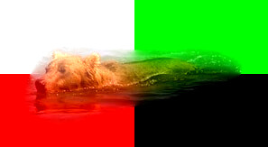
%IMG7%magick ^ %BEAR% ^ -crop 2x2@ ^ ( -clone 0 -fill White -colorize 100 ) ^ -delete 0 ^ ( -clone 0 -fill Lime -colorize 100 ) ^ -delete 0 ^ ( -clone 0 -fill Red -colorize 100 ) ^ -delete 0 ^ ( -clone 0 -fill Black -colorize 100 ) ^ -delete 0 ^ -layers merge ^ spm_chq.png |

|
call %PICTBAT%poissonPaste ^ spm_chq.png %BEAR% %MASK% ^ spm_chq_out.png |
|
The four background colours have clearly propagated into the bear. In this example, no alternative boundary is available, so we can't avoid the effect.
When we have a choice of boundaries, represented in examples above by a white ring, we have chosen the path that minimises the total difference between the input images.
Instead, we can choose the path that minimises the difference in the slopes (a.k.a. gradients; see the Slopes page) of the inputs. For both inputs, we calculate the slopes and record x- and y-deltas for each colour channel in two images (because we need six channels). For each channel we then calculate the difference between the slopes, and use the maximum magnitude of these as the input to the darkestpntpnt process module.
(Instead of using six channels, we could instead use the slopes of the grayscaled images, needing just two channels.)
For the slope*.bat scripts, see the Slopes page.
Below, "-sigmoidal-contrast" and "-auto-level" are merely to aid visibility.
|
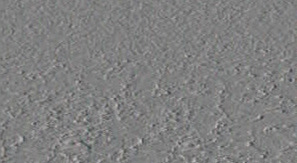
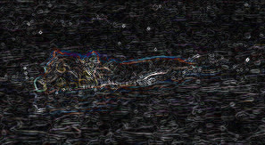
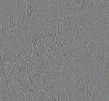
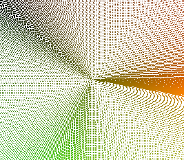
Get the slope of the bear image. call %PICTBAT%slopeXY ^ %BEAR% spm_bear_slp.miff %IMG7%magick spm_bear_slp.miff[0] ^ -evaluate Divide 2 ^ -evaluate Add 50%% ^ -sigmoidal-contrast 10,50%% ^ spm_bear_slp_0.jpg %IMG7%magick spm_bear_slp.miff[1] ^ -evaluate Divide 2 ^ -evaluate Add 50%% ^ -sigmoidal-contrast 10,50%% ^ spm_bear_slp_1.jpg |
|
|
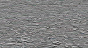
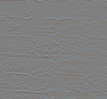
Get the slope of the water image. call %PICTBAT%slopeXY ^ spm_back_crp.png spm_water_slp.miff %IMG7%magick spm_water_slp.miff[0] ^ -evaluate Divide 2 ^ -evaluate Add 50%% ^ -sigmoidal-contrast 10,50%% ^ spm_water_slp_0.jpg %IMG7%magick spm_water_slp.miff[1] ^ -evaluate Divide 2 ^ -evaluate Add 50%% ^ -sigmoidal-contrast 10,50%% ^ spm_water_slp_1.jpg |
|
|
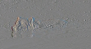
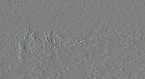
Subtract: slope(water) - slope(bear) call %PICTBAT%slopeXYminus ^ spm_bear_slp.miff spm_water_slp.miff ^ spm_minus_slp.miff %IMG7%magick spm_minus_slp.miff[0] ^ -evaluate Divide 2 ^ -evaluate Add 50%% ^ -sigmoidal-contrast 10,50%% ^ spm_minus_slp_0.jpg %IMG7%magick spm_minus_slp.miff[1] ^ -evaluate Divide 2 ^ -evaluate Add 50%% ^ -sigmoidal-contrast 10,50%% ^ spm_minus_slp_1.jpg |
|
|
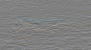
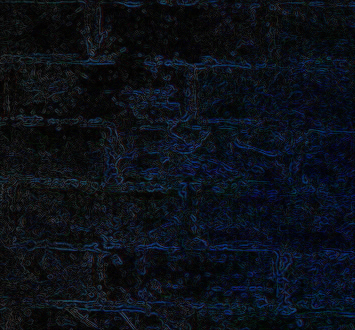
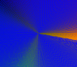
Get the magnitude of the slope difference. call %PICTBAT%slopeXYmag ^ spm_minus_slp.miff ^ spm_mag_slp.miff %IMG7%magick spm_mag_slp.miff ^ -auto-level ^ spm_mag_slp.jpg |
|
|
Find the line of minimum total magnitude within the ring,
call %PICTBAT%minDp ^ spm_mag_slp.miff spm_hue_bw2.png ^ spm_mag_msk.png |
|
|
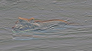
Poisson-paste. call %PICTBAT%poissonPaste ^ spm_back_crp.png %BEAR% spm_mag_msk.png ^ spm_mag_out.png |
|
In some ways, this result is more accurate than previous results, creating less bleeding of features from the background to the new foreground. However, the boundary in this example is also tighter, closer to the bear. We have less of the bear's reflection in the water.
Ordinary (non-guided) Poisson Image Editing creates a result that has a gradient very close to g, the required foreground ("source"). The result is made by adding a membrane to the foreground, where the membrane was made by relaxing a boundary of (background minus foreground).
Guided Poisson Image Editing creates a result that has a gradient very close to v, called a "guidance vector field". v is set to some function of g and f* (the original background). The result is made from the membrane itself, not added to anything, and the membrane is made by relaxing a boundary of simply the background. But the method of relaxation is more complicated.
The guidance vector field might come from the gradient of a single image, or from a mixture of gradients of different images (aka mixed gradients).
Below, spm_ws_div.miff is the right hand side of the equation:
f(x-1,y) + f(x+1,y) + f(x,y-1) + f(x,y+1) - 4*f(x,y) = rhs(x,y)
So each iteration is:
f(x,y) = f(x-1,y) + f(x+1,y) + f(x,y-1) + f(x,y+1) - rhs(x,y)
                             4                          4
In IM terms: convolve once, subtract something, convolve again, subtract the same thing, and keep going.
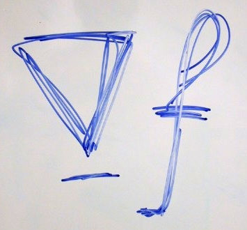
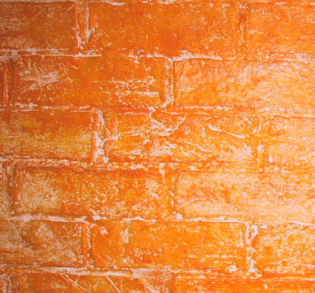
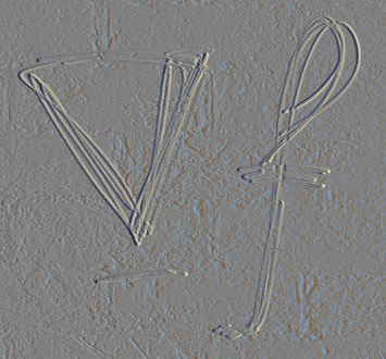
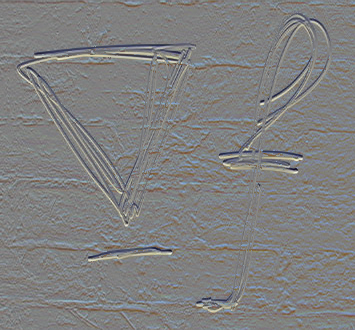
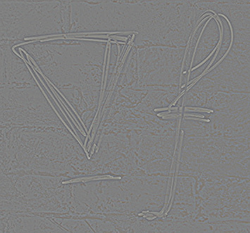
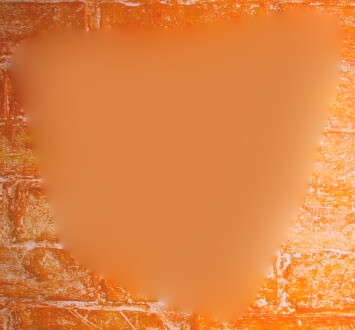
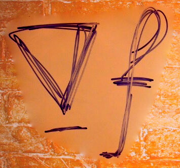
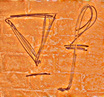
For example, we take two other images from the Pérez paper:
|
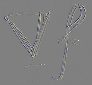
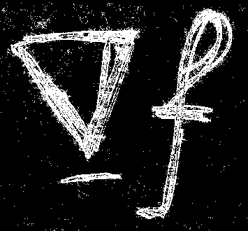
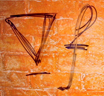
A scribble image. set SCRIBBLE=perez_scribble.jpg |
|
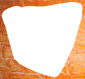
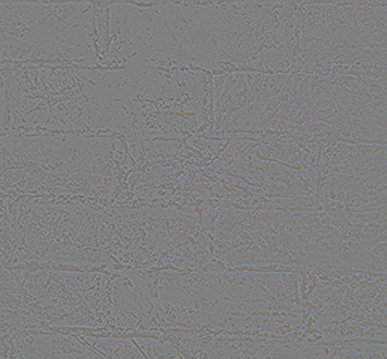
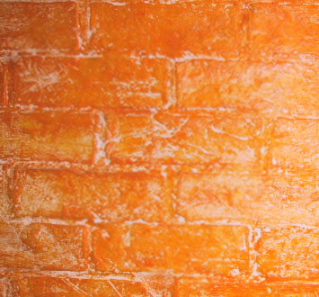
|
A wall image, cropped to the same size as the scribble. %IMG7%magick ^ %SCRIBBLE% ^ perez_wall.jpg ^ -compose Over -composite ^ spm_wall_crp.png set WALL=spm_wall_crp.png |
|
|
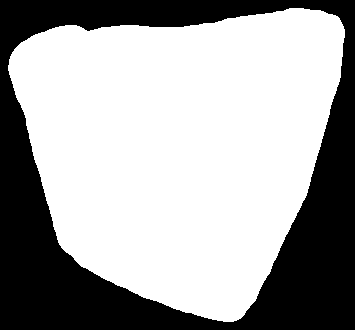
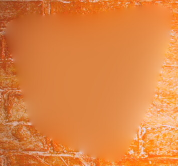
Make a mask in Gimp, roughly the same as the Pérez paper. set WS_MASK=perez_ws_mask.png |
|
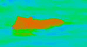
For the result: where the mask is black, we want the wall. Where the mask is white, we want the gradient of either the wall or the scribble, whichever is more significant at that pixel.
To do that, we find the gradients (on x and y directions) of both images; find the magitudes of each gradient; find which magnitude is greater; for each pixel, use the slope of the image with the greatest magnitude; find the divergence of that.
|
Slope of the scribble. call %PICTBAT%slopeXY ^ %SCRIBBLE% spm_scrb_sxy.miff %IMG7%magick ^ spm_scrb_sxy.miff[0] ^ -evaluate Divide 2 ^ -evaluate Add 50%% ^ spm_scrb_sxy_0.png %IMG7%magick ^ spm_scrb_sxy.miff[1] ^ -evaluate Divide 2 ^ -evaluate Add 50%% ^ spm_scrb_sxy_1.png |
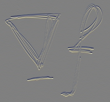
|
|
Slope of the wall. call %PICTBAT%slopeXY ^ %WALL% spm_wall_sxy.miff %IMG7%magick ^ spm_wall_sxy.miff[0] ^ -evaluate Divide 2 ^ -evaluate Add 50%% ^ spm_wall_sxy_0.png %IMG7%magick ^ spm_wall_sxy.miff[1] ^ -evaluate Divide 2 ^ -evaluate Add 50%% ^ spm_wall_sxy_1.png |
|
|
Magnitude of the scribble slope. call %PICTBAT%slopeXYmag ^ spm_scrb_sxy.miff spm_scrb_mag.miff |

|
|
Magnitude of the wall slope. call %PICTBAT%slopeXYmag ^ spm_wall_sxy.miff spm_wall_mag.miff |
|
|
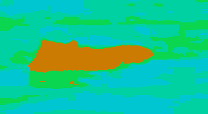
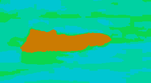
Which magnitude is greatest? White for scribble, black for wall. %IMG7%magick ^ spm_wall_mag.miff spm_scrb_mag.miff ^ -colorspace Gray ^ -compose MinusDst -composite ^ -threshold 0 ^ spm_ws_mag_diff.png |
|
|
Use the slope that has the greatest magnitude. rem FIXME: Can't use mpr??
%IMG7%magick ^
-define compose:clamp=off ^
( spm_wall_sxy.miff[0] ^
spm_scrb_sxy.miff[0] ^
spm_ws_mag_diff.png +write mpr:MSK ^
-alpha off ^
-compose Over -composite ^
) ^
( spm_wall_sxy.miff[1] ^
spm_scrb_sxy.miff[1] ^
spm_ws_mag_diff.png ^
-alpha off ^
-compose Over -composite ^
) ^
-define quantum:format=floating-point ^
spm_ws_mxslp.miff
%IMG7%magick ^
spm_ws_mxslp.miff[0] ^
-evaluate Divide 2 ^
-evaluate Add 50%% ^
spm_ws_mxslp_0.png
%IMG7%magick ^
spm_ws_mxslp.miff[1] ^
-evaluate Divide 2 ^
-evaluate Add 50%% ^
spm_ws_mxslp_1.png
|
|
|
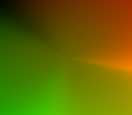
Find the divergence. call %PICTBAT%slopeXYdiv ^ spm_ws_mxslp.miff spm_ws_div.miff %IMG7%magick ^ spm_ws_div.miff ^ -evaluate Divide 2 ^ -evaluate Add 50%% ^ spm_ws_div.jpg This will be subtracted after each blur. |
|
This divergence is the required slope of the slope of the result. The divergence image will contain negative and positive values, with a mean somewhere near zero.
|
With the mask, make a hole in the wall. %IMG7%magick ^ %WALL% ^ ( %WS_MASK% -negate ) ^ -alpha off ^ -set option:compose:outside-overlay false ^ -compose CopyOpacity -composite ^ spm_wall_msk.miff |
|
We relax-fill the hole, using the divergence as the guidance field.
call %PICTBAT%relaxFillMS ^
  spm_wall_msk.miff . spm_wall_msk_rfs2.miff ^
  0.001 1000 . spm_ws_div.miff
0 00:01:49 |
|
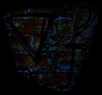
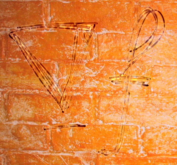
This is essentially the same result as in the Pérez paper. The blue scribble has become purple, i.e. it has increased in redness. This is because the wall is redder than the scribble, at the boundary.
We can test the "null" fill by calculating the div of the wall, and using that as the guidance to fill the hole in the wall.
|
Find the divergence. call %PICTBAT%slopeXYdiv ^ spm_wall_sxy.miff spm_wall_div.miff %IMG7%magick ^ spm_wall_div.miff ^ -evaluate Divide 2 ^ -evaluate Add 50%% ^ spm_wall_div.jpg This will be subtracted after each blur. |
|
|
Relax-fill with this divergence. call %PICTBAT%relaxFillMS ^ spm_wall_msk.miff . spm_wall_fill_wall.miff ^ 0.001 1000 . spm_wall_div.miff We have reconstructed the wall. |
|
The result is very similar to the original wall image, but slightly blurred, as if the wall has been given "-blur 0.46".
Other results:
|
Make a black image, and holed black image. %IMG7%magick ^ %WALL% ^ -alpha off ^ -fill Black -colorize 100 ^ +depth ^ +write spm_ws_gray.png ^ ( %WS_MASK% -negate ) ^ -alpha off -compose CopyOpacity -composite ^ spm_ws_gray_m.png |


|
|
Relax the holed wall. call %PICTBAT%relaxFillMS ^ spm_wall_msk.miff . spm_wall_msk_rf.miff |
|
|
Relax the holed wall, guided by gray(50%), ie zero. call %PICTBAT%relaxFillScr ^ spm_wall_msk.miff . spm_wall_msk_gr_rfs.miff ^ 0.001 100 . spm_ws_gray.png The result is the same (but slower). |
|
|
Relax the holed gray(50%), guided by the divergence. call %PICTBAT%relaxFillScr ^ spm_ws_gray_m.png . spm_gray_rfs.miff ^ 0.001 100 . spm_ws_div.miff |
|
|
Poisson-paste, with user-defined mask. call %PICTBAT%poissonPaste ^ %WALL% %SCRIBBLE% perez_ws_mask.png ^ spm_ws_out2.png |
|
|
Poisson-paste, with max-magnitude mask. call %PICTBAT%poissonPaste ^ %WALL% %SCRIBBLE% spm_ws_mag_diff.png ^ spm_ws_out4.png |
|
|
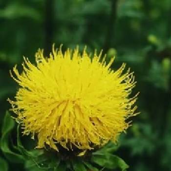
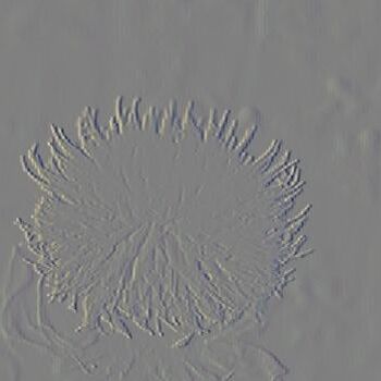
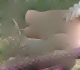
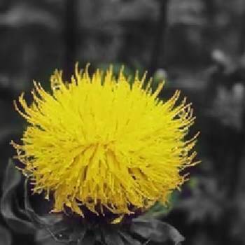
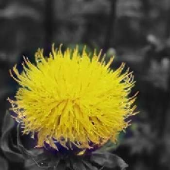
Another image from the Pérez paper. %IMG7%magick ^ perez_flower.jpg ^ -crop 350x350+0+0 +repage ^ spm_flower.png set FLOWER=spm_flower.png |
|
|
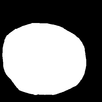
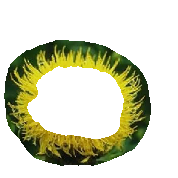
A loose mask, made in Gimp. set FLR_MASK=flower_mask.png |
|
The mask is very loose, entirely surrounding the flower; we haven't bothered to try and capture just the tendrils.
The goal is to make the background (the non-flower) monochrome, without changing the flower.
|
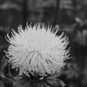
Gray version of flower. %IMG7%magick ^ %FLOWER% ^ -colorspace Gray ^ +depth ^ spm_flr_gr.png |
|
|
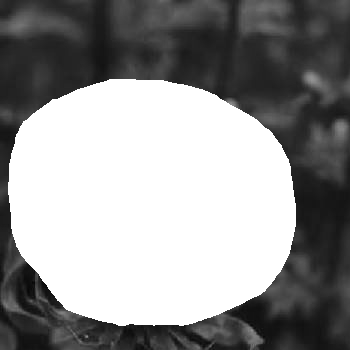
Gray version, with hole. %IMG7%magick ^ spm_flr_gr.png ^ ( %FLR_MASK% -negate ) ^ -alpha off ^ -compose CopyOpacity -composite ^ spm_flr_gr_h.png |
|
|
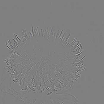
Slope of colour flower. call %PICTBAT%slopeXY ^ %FLOWER% spm_flr_sxy.miff %IMG7%magick ^ spm_flr_sxy.miff[0] ^ -evaluate Divide 2 ^ -evaluate Add 50%% ^ spm_flr_sxy_0.png %IMG7%magick ^ spm_flr_sxy.miff[1] ^ -evaluate Divide 2 ^ -evaluate Add 50%% ^ spm_flr_sxy_1.png |
|
|
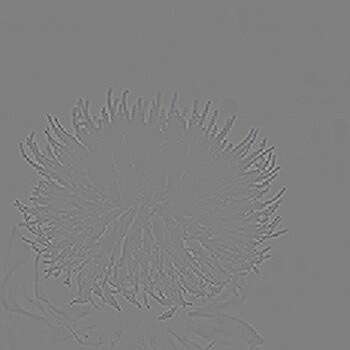
Divergence of slope of flower. call %PICTBAT%slopeXYdiv ^ spm_flr_sxy.miff spm_flr_div.miff %IMG7%magick ^ spm_flr_div.miff ^ -evaluate Divide 2 ^ -evaluate Add 50%% ^ spm_flr_div.png We will use this as the guidance field. |
|
|
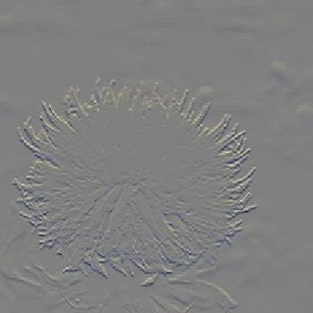
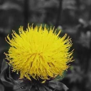
Relax-fill the holed grayscale version, with guidance. call %PICTBAT%relaxFillMS ^ spm_flr_gr_h.png . spm_flr_bwc.png ^ 0.001 1000 . spm_flr_div.miff A good result, but the entire flower has become slightly gray. |

|
This is essentially the same result as shown in the Pérez paper.
If the result seems too good to be true, well, it is.
Where the mask is black, the result is grayscale, of course. Where the mask is white, the result is the colour input with green "subtracted" (speaking approximately). So the flower has become less green: values in the green channel have decreased, while values in the red and blue channels have increased. This has happened because that is the change at the boundary. Similarly, yellow colour has leached out from the flower to the grayscale areas between the tendrils. This is addressed in Inner Dirichlet boundary below.
The guidance field might be from the background image, but modulated in some way.
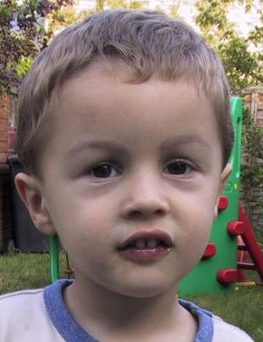
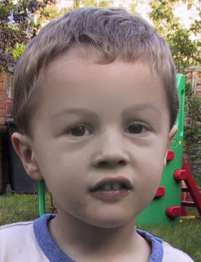
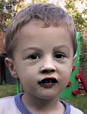
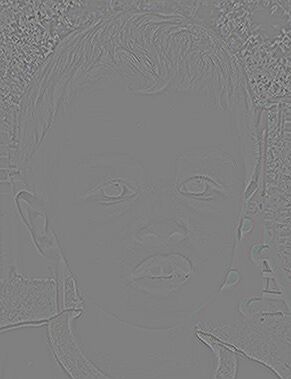
Yet another image from the Pérez paper:
set BOY=perez_boy.jpg |
|
|
With Gimp, make a mask that includes just the facial features. set BOY_MASK=boy_mask.png |
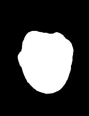
|
|
Get the slope of BOY. call %PICTBAT%slopeXY ^ %BOY% spm_boy_sxy.miff Modify the slope. %IMG7%magick ^ spm_boy_sxy.miff ^ -fuzz 2%% -fill Black -opaque Black ^ -define quantum:format=floating-point ^ spm_boy_sxy2.miff Get the divergence of the modified slope. call %PICTBAT%slopeXYdiv ^ spm_boy_sxy2.miff spm_boy_div2.miff %IMG7%magick ^ spm_boy_div2.miff ^ -evaluate Divide 2 ^ -evaluate Add 50%% ^ spm_boy_div2.png |
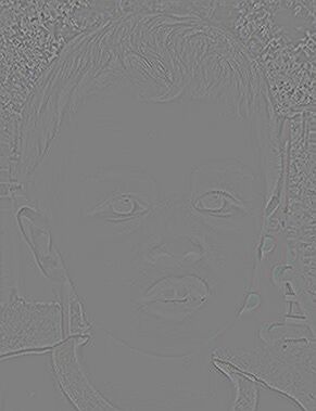
|
|
Poisson-paste. call %PICTBAT%poissonPaste ^ %BOY% . %BOY_MASK% ^ spm_boy_out2.png ^ . spm_boy_div2.miff |
|
We have adjusted the slope so where it is within ±2% of 50% (i.e. zero), it becomes 50%. This eliminates small changes in slope. It has a side-effect of reducing overall contrast, because slope accumulates to make contrast, [[ so we compensate very approximately with "-level -80%%,80%%", but this is a kludge.]] Instead, we could match the result to the input image, using either imgGainBias.bat or matchHisto.bat. Another option would be to match the adjusted slope to the non-adjusted slope.
In the next example, after eliminating small slopes, we sharpen the remaining slopes. This increases local contrast.
|
Modify the slope. %IMG7%magick ^ spm_boy_sxy.miff ^ -fuzz 2%% -fill Black -opaque Black ^ -unsharp 0x3+1+0 ^ -define quantum:format=floating-point ^ spm_boy_sxy3.miff Get the divergence of the modified slope. call %PICTBAT%slopeXYdiv ^ spm_boy_sxy3.miff spm_boy_div3.miff %IMG7%magick ^ spm_boy_div3.miff ^ -evaluate Divide 2 ^ -evaluate Add 50%% ^ spm_boy_div3.png |
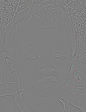
|
|
Poisson-paste. call %PICTBAT%poissonPaste ^ %BOY% . %BOY_MASK% ^ spm_boy_out3.png ^ . spm_boy_div3.miff |
|
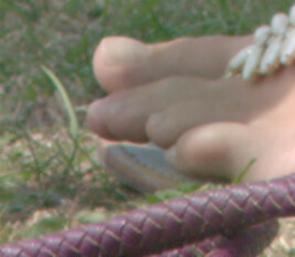
This seems useful, so we put that in a script, poissonSmooth.bat. The script creates its own mask, which is black at the four edges, and otherwise white. At large values of sigma, it is effective at removing paper texture from scanned documents. This is a form of adaptive blur; see also Adaptive blur and sharpen.
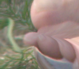
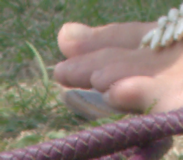
call %PICTBAT%poissonSmooth ^ toes.png spm_psm1.png 1 |
|
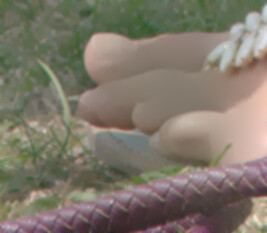
call %PICTBAT%poissonSmooth ^ toes.png spm_psm2.png 3 |
|
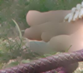
call %PICTBAT%poissonSmooth ^ toes.png spm_psm3.png 5 |
|
call %PICTBAT%poissonSmooth ^ toes.png spm_psm4.png 10 |
|
A different effect is obtained by increasing the contrast of divergence, around the 50% level. This changes the slope of the slope of the result (increasing overall contrast), so a small change here goes a long way.
%IMG7%magick ^ spm_boy_div2.miff ^ -evaluate Divide 2 -evaluate Add 50%% ^ -sigmoidal-contrast 2,50%% ^ -evaluate Subtract 50%% -evaluate Multiply 2 ^ -define quantum:format=floating-point ^ spm_boy_div4.miff %IMG7%magick ^ spm_boy_div4.miff ^ -evaluate Divide 2 ^ -evaluate Add 50%% ^ spm_boy_div4.png |
|
|
Poisson-paste. call %PICTBAT%poissonPaste ^ %BOY% . %BOY_MASK% ^ spm_boy_out4.png ^ . spm_boy_div4.miff |

|
More generally, poissonPaste.bat gives us a method of modifying the pixels in part of an image and blending the modified part into the original; an alternative to alpha blending.
See Image Editing without Color Inconsistency Using Modified Poisson Equation, Qin Chuan, Wang Shuozhong, Zhang Xinpeng, 2008.
In examples above, the colour difference at the boundary has influenced all result pixels inside the boundary, so the bear has become lightened, the scribble has become purple, and the flower has become less green. This is also known as colour inconsistency or colour contamination. Sometimes we want this effect, but sometimes we don't.
The pixels to be filled already have an outer boundary condition, where the adjustment to be added is "water" minus "bear", so when this is added to "bear" the result at the outer boundary is "water". Chuan et al suggest we add an additional condition at the bear pixels, setting the adjustment to be added to "zero", so when this is added to "bear" the result at the inner boundary is "bear".
The script poissonPasteIDB.bat takes two masks, one for each of the outer and inner boundaries. The inner boundary mask is white where we want the bear unchanged, and black elsewhere.
Chuan et al suggest the user should create the bear mask. But we have created one automatically, so we can use that. We shrink spm_hue_bw.png by a few pixels. Black now has pixels that are in the bear. Add this to MASK, so now we have a white ring that is to be solved by Poisson equation.
The two masks together form what is often called a trimap; a map that labels some pixels as certainly inside the object, some as certainly outside, and others as unknown.
For non-guided Poisson-pasting, poissonPasteIDB does the following:
For guided pasting, poissonPasteIDB does the following:
As a happy side-effect: the area to be filled is now the ring between the outer and inner masks. This ring shape is smaller than before, so fewer pixels need filling by relaxFillMS.bat, so this is faster than without an inner mask.
|
Create the inner boundary mask. %IMG7%magick ^ spm_hue_bw.png ^ -morphology Dilate disk:3 ^ -negate ^ spm_bear_sm.png |
|
call %PICTBAT%poissonPasteIDB ^ spm_back_crp.png %BEAR% ^ %MASK% spm_bear_sm.png ^ spm_idb_out.png |
|
|
Another example:
call %PICTBAT%poissonPasteIDB ^ spm_chq.png %BEAR% ^ %MASK% spm_bear_sm.png ^ spm_idb_out2.png |
|
The result has pixels at the outer boundary the same colour as the background, and pixels at the inner boundary the same colour as the bear. Hence we now have colour consistency.
We can do the same trick with the flower.
|
Create the inner boundary mask with Gimp.
set FLR_IN_MASK=flower_inner_mask.png %IMG7%magick ^ %FLR_IN_MASK% ^ -alpha off ^ %FLR_IN_MASK% |
|
|
Check the masks. %IMG7%magick ^ %FLR_MASK% ^ ( %FLR_IN_MASK% -negate ) ^ -compose Darken -composite ^ %FLOWER% ^ +swap ^ -alpha off ^ -compose CopyOpacity -composite ^ -alpha Background ^ +depth ^ spm_flr_chk.png |
|
|
Poisson-paste the grayscale version. call %PICTBAT%poissonPasteIDB ^ spm_flr_gr.png %FLOWER% ^ %FLR_MASK% %FLR_IN_MASK% ^ spm_flr_bwc3.png The tendrils have lost some colour, become whiter. |
|
|
Poisson-paste the grayscale version, with guidance. call %PICTBAT%poissonPasteIDB ^ spm_flr_gr.png %FLOWER% ^ %FLR_MASK% %FLR_IN_MASK% ^ spm_flr_bwc4.png ^ . spm_flr_div.miff The tendrils are a good colour, but have slightly blurred. |

|
However, the tendrils have become somewhat gray and the monochrome areas between tendrils have become somewhat yellow. Chuan et al suggest a solution. In the guidance field, where the pixels represent either the yellow flower or the grayscale background, the values are low (i.e. close to zero). At the border between the flower and background, the gradient field has relatively high values (i.e. more distant from zero). If we make the high values even higher, we will get a steeper gradient between the two, so less colour bleed. Where the gradient field is above a certain threshold, they increase the values by a certain factor. For the threshold, they use 80% of the maximum value M. For the factor, they use K. They calculate:
ForeIn: mean of foreground at the inner boundary
ForeOut: mean of foreground at the outer boundary
BackOut: mean of background at the outer boundary
K = ForeIn - BackOut
    ForeIn - ForeOut

M = max(guidance_field)
I suppose the same multiplier is applied to all three channels. But what if K is less than one? Less than zero?
More simply, we can sharpen the guidance field. Before August 2023, we didn't need to add and subtract 50% around the -unsharp. But some recent update to IM causes problems when we have negative values: they become far too negative.
|
Sharpen the guidance. %IMG7%magick ^ spm_flr_div.miff ^ -evaluate Add 50%% ^ -unsharp 0x0.5+1+0.05 ^ -evaluate Subtract 50%% ^ -depth 32 ^ -define quantum:format=floating-point ^ spm_flr_div_u.miff %IMG7%magick ^ spm_flr_div_u.miff ^ -evaluate Divide 2 ^ -evaluate Add 50%% ^ spm_flr_div_u.png |
|
|
Poisson-paste the grayscale version, with sharpened guidance. call %PICTBAT%poissonPasteIDB ^ spm_flr_gr.png %FLOWER% ^ %FLR_MASK% %FLR_IN_MASK% ^ spm_flr_bwc5.png ^ . spm_flr_div_u.miff This has reduced the bleed of yellow into the monochrome,
|
|
As an alternative to the previous, we can restore the sharpness with a small "-unsharp" applied just in the transition area, between the two masks:
%IMG7%magick ^
  spm_flr_bwc4.png ^
  ( +clone -unsharp 0x0.5+1+0 ) ^
  ( %FLR_IN_MASK% -negate ^
    %FLR_MASK% ^
    -compose Darken -composite ^
  ) ^
  -compose Over -composite ^
  spm_flr_bwc4_u.png
|
|
I regard this as the best result for the yellow flower on grayscale background.
Above, we have seen that colour-change at the boundary is propagated inwards, creating a colour cast. We have seen this can be prevented by an inner Dirichlet boundary. On the other hand, we can use this to our advantage.
Poisson pasting can be used to correct colours when photographs are to be joined with overlaps ("stitched"), such as panoramas or aerial photography. Suppose we have these three input images:
|
#1: %IMG7%magick ^
-size 150x100 xc: ^
-sparse-color bilinear ^
0,0,#67f,0,%%[fx:h-1],#6f7,%%[fx:w-1],0,#45d ^
-gravity Center -pointsize 30 ^
-fill Black -annotate +0+0 "#1" ^
-fill White -annotate -2-2 "#1" ^
spm_pan_in1.png
|

|
|
#2: %IMG7%magick ^
-size 150x100 xc: ^
-sparse-color bilinear ^
0,0,#f88,0,%%[fx:h-1],#7f6,%%[fx:w-1],0,#faa ^
-fill White -gravity Center -pointsize 30 ^
-fill Black -annotate +0+0 "#2" ^
-fill White -annotate -2-2 "#2" ^
spm_pan_in2.png
|
|
|
#3: %IMG7%magick ^
-size 150x100 xc: ^
-sparse-color bilinear ^
0,0,#a6f,0,%%[fx:h-1],#8d7,%%[fx:w-1],0,#c7f ^
-fill White -gravity Center -pointsize 30 ^
-fill Black -annotate +0+0 "#3" ^
-fill White -annotate -2-2 "#3" ^
spm_pan_in3.png
|
|
Suppose they should overlap like this:
set OFFS_2=+130+10 set OFFS_3=+250-10 %IMG7%magick ^ spm_pan_in1.png ^ ( spm_pan_in2.png -repage %OFFS_2% ) ^ ( spm_pan_in3.png -repage %OFFS_3% ) ^ -background None ^ -layers merge +repage ^ spm_pan_out1.png set CROP_2=150x100%OFFS_2% |

|
There are many possible ways to blend these images, including:
We will use the third way.
The boundary condition, where we require the images to match, are at most of the left edge of #2 and part of the top (an inverted "L"), and an "L" shape near the right edge of #2.
We make a mask of the "L" shapes. The following is messy but depends only on the image sizes, their order, and the "-repage" arguments. "-fuzz" is used in case twice gray(50%) isn't exactly white. "-layers merge" puts offsets in the output, in this case +0-10, so we can later use #2 offsets directly for cropping.
"-set colorspace sRGB" is needed for IM v7, to get three channels. In IM v7, "-border" uses the current "-compose" method, so we need to explicitly use "plus".
%IMG7%magick ^
  -size 150x100 ^
  xc:gray(50%%) -set colorspace sRGB ^
  -fuzz 0.1%% ^
  ( xc:Red ^
    -shave 1x1 -bordercolor gray(50%%) -border 1 ^
    -repage %OFFS_2% ^
  ) ^
  -background Black ^
  -compose Plus -layers merge +repage ^
  -fill gray(50%%) -opaque Red ^
  ( xc:Red ^
    -shave 1x1 ^
      -compose Over ^
      -bordercolor gray(50%%) -border 1 ^
    -repage %OFFS_3% ^
  ) ^
  -background Black ^
  -compose Plus -layers merge ^
  -fill Black +opaque White ^
  spm_L-both.png
Note: the output has offsets. |

|
|
Crop to #2: %IMG7%magick ^ spm_L-both.png ^ -crop %CROP_2% +repage ^ spm_L_cr.png |
|
We use this to blend image #2 with the other two images.
|
Subtract #2 from the others: %IMG7%magick ^
spm_pan_in1.png ^
( spm_pan_in3.png -repage %OFFS_3% ) ^
-background None ^
-layers merge ^
( spm_pan_in2.png -repage %OFFS_2% ) ^
-compose Mathematics ^
-define compose:args=0,-0.5,0.5,0.5 ^
-layers merge ^
spm_pan_sub.png
Note: output has offsets. |

|
|
Crop to #2: %IMG7%magick ^ spm_pan_sub.png ^ -crop %CROP_2% +repage ^ spm_pan_sub_cr.png |
|
|
Mask by the L-shapes: %IMG7%magick ^ spm_pan_sub_cr.png ^ spm_L_cr.png ^ -compose CopyOpacity -composite ^ spm_pan_sub_lcr.png |
|
|
Relax-fill to get an adjustment image: call %PICTBAT%relaxFillMS ^ spm_pan_sub_lcr.png . spm_pan_rf.png ^ 1e-6 1000 |

|
|
Add the adjustment image to #2: %IMG7%magick ^
spm_pan_in2.png ^
spm_pan_rf.png ^
-compose Mathematics ^
-define compose:args=0,2,1,-1 -composite ^
spm_pan_2adj.png
|

|
|
Merge the modified #2 with the original #1 and #3: %IMG7%magick ^ spm_pan_in1.png ^ ( spm_pan_2adj.png -repage %OFFS_2% ) ^ ( spm_pan_in3.png -repage %OFFS_3% ) ^ -background None -compose Over ^ -layers merge +repage ^ spm_pan_123.png |

|
As required, the images blend seamlessly. Image #2 has been adjusted to exactly match two adjacent images. If image #2 had been entirely surrounded by other images, similar processing could be done.
The script colCorr2.bat composites one image over another, at a given offset, with colour-correction to the top image. We can use the script to composite successive images over previous results. For example:
|
Composite #2 over #1: call %PICTBAT%colCorr2 ^ spm_pan_in1.png spm_pan_in2.png %OFFS_2% ^ spm_cc_12.png |

|
|
Composite #3 over previous result: call %PICTBAT%colCorr2 ^ spm_cc_12.png spm_pan_in3.png %OFFS_3% ^ spm_cc_123.png |

|
This result is different to the previous one. Instead of adjusting #2 to match both #1 and #3, we adjust #2 to match just #1, then adjust #3 to match the adjusted #2.
We can readily add further conditions. For example, we might want the central column of image #2 to be unchanged. This needs gray(50%) in the adjustment image.
|
Add a gray line: %IMG7%magick ^ spm_pan_sub_lcr.png ^ -stroke gray(50%%) ^ -draw "line 75,0,75,99" ^ spm_pan_sub_lcr2.png |
|
|
Relax-fill to get an adjustment image: call %PICTBAT%relaxFillMS ^ spm_pan_sub_lcr2.png . spm_pan_rf2.png ^ 1e-6 1000 |

|
|
Add the adjustment image to #2: %IMG7%magick ^
spm_pan_in2.png ^
spm_pan_rf2.png ^
-compose Mathematics ^
-define compose:args=0,2,1,-1 -composite ^
spm_pan_2adj2.png
|
|
|
Merge: %IMG7%magick ^ spm_pan_in1.png ^ ( spm_pan_2adj2.png -repage %OFFS_2% ) ^ ( spm_pan_in3.png -repage %OFFS_3% ) ^ -background None -compose Over ^ -layers merge +repage ^ spm_pan_1232.png |

|
We can do a similar trick in the script, by adding a small gray circle in the centre of the adjustment image:
|
Composite #2 over #1: set cc2DRAW=circle 75,50 80,50 call %PICTBAT%colCorr2 ^ spm_pan_in1.png spm_pan_in2.png %OFFS_2% ^ spm_cc_12b.png |

|
|
Composite #3 over previous result: call %PICTBAT%colCorr2 ^ spm_cc_12b.png spm_pan_in3.png %OFFS_3% ^ spm_cc_123b.png set cc2DRAW= |

|
The technical papers in the references above (Pérez etc) describe the mathematics of Poisson image editing. Here is a less-mathematical explanation. The goal is to create an image where some pixels have desired values (the boundary constraint) while others are such that the slope either changes as slowly as possible, or the rate of change follows a guidance.
I visualise this as the pixel values at the boundary points representing heights, and we stretch a thin rubber membrane, and glue it to all the boundary points. Then the height of the rubber membrane at points inside the boundary are the required pixels values at those points. At the initial guess, which might be some constant value, the membrane is over-stretched adjacent to the boundary points, and not at all stretched between other points. We need to "relax" the membrane so it is equally stretched at all points. At each infinitely small point of the membrane, the forces on that point caused by the stretches in all directions must sum to zero. If the sum wasn't zero, there would be a net force on the point, so it would move.
We simulate the forces and movement in software. Suppose a pixel has a value 0.2, and it has two adjacent pixels with values 1.0 and 0.1, then there is a net force pulling that pixel upwards, to a new value that is the average of 1.0 and 0.1, which is 0.55.
This new value will change forces on any adjacent pixels, so they need to be re-calculated. The process repeats until no values change more than a specified threshold, or we hit a limit on the number of iterations.
In pratice, we set each pixel to the average of four neighbours, the pixels to the north, south, east and west. Instead, we could use the eight adjacent neighbours. This would give the same final result, with virtually no impact on performance.
We can think of this as an infill process. When fully-transparent pixels have an unknown colour, surrounded by boundary pixels of known colours, we "relax-fill" the missing pixels.
More mathematically (sorry), we can think of this as millions of unknowns (the pixel values), with the same number of simultaneous equations.
The script relaxFill.bat aims at a zero rate of change of gradient.
At each iteration, for every pixel (and every channel), we set the new pixel value to the average value of the four neighbours to the north, south, east and west. This is a blurring operation. If we repeat this often enough, every pixel will be almost equal to the average of the four neighbours. This means the slope (gradient) of the image will be almost the same everywhere. It doesn't change quickly. Put it another way, the slope of the slope (the "second derivative") will be almost zero.
Generally, pixels won't be exactly equal to the average of the neighbours. That happens only when the result is a bilinear gradient, which only happens when the boundary values when considered as heights are co-planar. But the repeated iteration gets the overall image as close to this result as it can get.
A bit of maths (sorry): if we say that each pixel value is a function of x and y, the pixel is f(x,y), then the following is approximately true for every pixel in the relaxed result:
f(x-1,y) + f(x+1,y) + f(x,y-1) + f(x,y+1) - 4*f(x,y) = 0
The left hand side of that equation approximates the slope of the slope of the image.
To get to that state, each iteration sets a new value for each pixel f'(x,y):
f'(x,y) = f(x-1,y) + f(x+1,y) + f(x,y-1) + f(x,y+1)
                              4
In ImageMagick code, this is:
-morphology convolve:n 3x3:0,0.25,0,0.25,0,0.25,0,0.25,0
... where n is however many iterations we want to make between each test for completion.
The iterative process has to start somewhere. We need an initial guess at the result, and each iteration takes us closer to the actual result. With luck there is no local minimum so the initial guess doesn't matter; any initial guess will eventually give us the same result. But the closer the initial guess is to the actual result, the quicker we will get there.
The relaxFillScr.bat is a little more complex. Instead of aiming to set the slope of the slope to zero for every pixel, it aims at some other particular slope of the slope for each pixel. The values to be aimed at are given in the guidance image. So in the relaxed result, the following is approximately true:
f(x-1,y) + f(x+1,y) + f(x,y-1) + f(x,y+1) - 4*f(x,y) = guide(x,y)
So each iteration is:
f'(x,y) = f(x-1,y) + f(x+1,y) + f(x,y-1) + f(x,y+1) - guide(x,y)
                              4                           4
IM can't do this in a single operation. (For example, morphology can't use more than one image as input.) So each iteration has two phases: first we convolve as above, then we subtract another image. These phases fight each other: we smooth then roughen the image, and repeat this smoothing and roughening. This makes the process slow to converge.
In preparation for the script, we set the guidance image to the divergence of the required gradient, so it is the sum of the slope of the slope in the x and y directions.
This calls either relaxFill.bat or relaxFillScr.bat at multiple scales. For relaxFill.bat, this always improves performance. However, for relaxFillScr.bat the improvement may be small or even negative.
A recursive mechanism is used, dividing the dimensions by two while the minimum dimension is greater than 50. At each level in the recursive stack, the script resizes images and calls either relaxFill.bat or relaxFillScr.bat, using the previous result as the initial guess. In the initial levels, striving for high accuracy is a waste of effort so the target score is relaxed by a factor that is the ratio of the areas (which is roughly four) at each level.
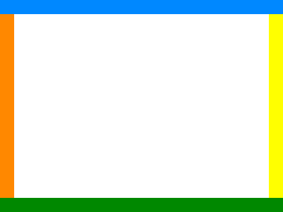
Here is a simple example using relaxFillMS.bat to relax-fill with no explicit guidance:
|
Example image, with transparent centre: %IMG7%magick ^
-size 400x300 xc:None ^
-size 20x300 ^
xc:#f80 -gravity West -composite ^
xc:#ff0 -gravity East -composite ^
-size 400x20 ^
xc:#08f -gravity North -composite ^
xc:#080 -gravity South -composite ^
spm_bnd.png
|
|
|
Relax-filled: call %PICTBAT%relaxFillMS ^ spm_bnd.png . spm_bnd_rf.png |
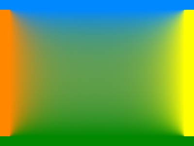
|
When the image to be filled is very sparse, the result may quickly converge to a poor solution.
We can aim for a low difference between successive approximations. Or we can specify a large number of iterations between tests. Or we can attempt a better approximation for the first guess. A -sparse-color with Shepards method, using a power of 1.0, works well.
|
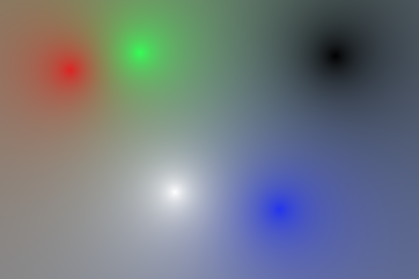
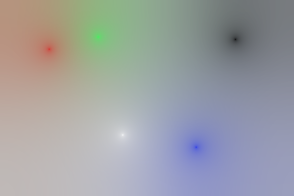
Make a sample sparse image, and a same-size Shepard's sparse colour image. %IMG7%magick ^ -size 600x400 xc:None ^ -fill #d22 -draw "point 100,100" ^ -fill #3f5 -draw "point 200,75" ^ -fill #fff -draw "point 250,275" ^ -fill #23e -draw "point 400,300" ^ -fill #000 -draw "point 480,80" ^ +write spm_sparse.png ^ +write sparse-color:spm_shep.lis ^ -define shepards:power=1 ^ -sparse-color shepards @spm_shep.lis ^ spm_shep.png |
|
|
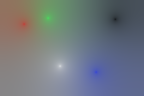
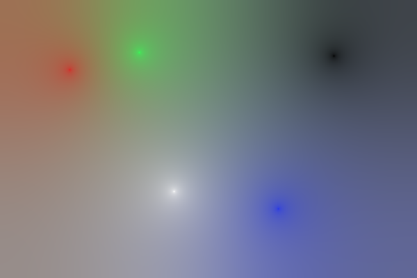
Relax-fill the image. call %PICTBAT%relaxFillMS ^ spm_sparse.png ^ spm_shep.png ^ spm_sparse_result.png ^ 0.0001 1000 |
|
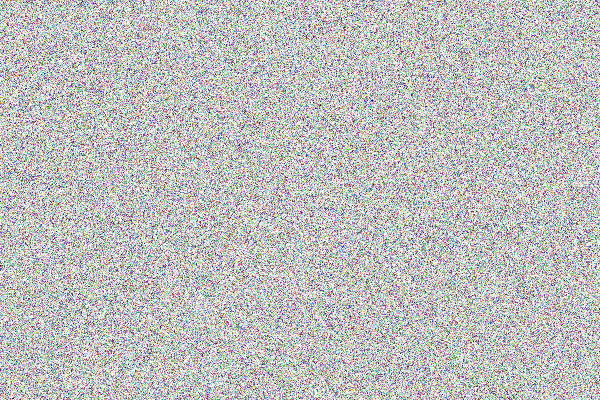
An alternative remedy is to use an initial guess that is pure noise. This is, of course, a very poor initial guess, and it ensures convergence does not occur quickly.
|
Make a same-size noisy image. %IMG7%magick ^ spm_sparse.png ^ +noise Random ^ spm_noise.png |
|
|
Relax-fill the image. call %PICTBAT%relaxFillMS ^ spm_sparse.png ^ spm_noise.png ^ spm_sparse_result2.png ^ 0.001 1000 |
|
|
If the process did not fully stabilize, the result may be partially transparent, so we remove transparency. %IMG7%magick ^ spm_sparse_result2.png ^ -alpha off ^ spm_sparse_opaq2.png |
|
This is a higher-level script. For inputs it uses a background, foreground and mask. The mask should be white where we want the adjusted foreground, and hence defines the area that will be relaxed.
The script optionally takes a guidance image.
This is like poissonPaste.bat, but takes an extra mask, that is white where we want the foreground to be unchanged. Hence the area to be relaxed is between the two masks.
If it is called with this inner mask blank or set to dot, ".", it instead calls poissonPaste.bat.
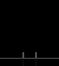
To further illustrate the relaxation process, we make a simple example, and show the intensity graphs at a cross-section through the images, at the middle row.
|
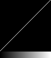
Create a background. %IMG7%magick ^ -size 200x200 gradient: ^ -rotate 90 ^ spm_xb.png call %PICTBAT%xSection spm_xb.png |

|
|
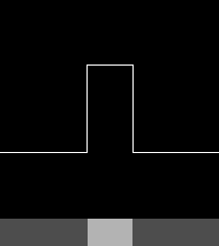
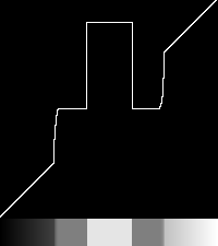
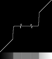
Create a foreground. The square is 40% lighter than its surround. %IMG7%magick ^ -size 200x200 xc:gray(30%%) ^ -fill gray(70%%) -draw "rectangle 80,80 120,120" ^ spm_xf.png call %PICTBAT%xSection spm_xf.png |

|
|
Create a mask. %IMG7%magick ^ -size 200x200 xc:Black ^ -fill White -draw "circle 100,100 150,100" ^ spm_xm.png |
|
The goal is to blend the background and foreground, where the mask is white.
We show the elapsed time for the process, and the number of iterations.
|
Poisson paste with minimal iterations. set rfCOMP_METRIC=PAE set ppTGT_SCORE=999 set ppNUM_STEPS=1 call %PICTBAT%poissonPaste ^ spm_xb.png spm_xf.png spm_xm.png ^ spm_xout1.png call %PICTBAT%xSection spm_xout1.png 0 00:00:01 rfmsITER=2 |

|
|
Poisson paste with a few iterations. set rfCOMP_METRIC=PAE set ppTGT_SCORE=0.1 set ppNUM_STEPS=10 call %PICTBAT%poissonPaste ^ spm_xb.png spm_xf.png spm_xm.png ^ spm_xout2.png call %PICTBAT%xSection spm_xout2.png 0 00:00:01 rfmsITER=20 |

|
|
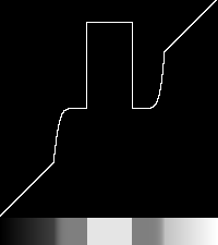
Poisson paste to approximate completion. set rfCOMP_METRIC=PAE set ppTGT_SCORE=0.001 set ppNUM_STEPS=1000 call %PICTBAT%poissonPaste ^ spm_xb.png spm_xf.png spm_xm.png ^ spm_xout3.png call %PICTBAT%xSection spm_xout3.png 0 00:00:09 rfmsITER=6000 In the finished result, the square is 40% lighter than its surround. |

|
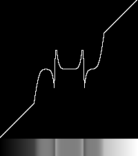
We will repeat the above, but with an explicit guidance field. First, we make a guidance field: the divergence of the slope of the foreground.
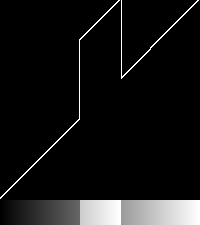
call %PICTBAT%slopeXY spm_xf.png spm_xf_sxy.miff call %PICTBAT%slopeXYdiv spm_xf_sxy.miff spm_xf_div.miff %IMG7%magick ^ spm_xf_div.miff ^ -evaluate Divide 2 ^ -evaluate Add 50%% ^ spm_xf_div.png call %PICTBAT%xSection ^ spm_xf_div.miff ^ spm_xf_div_xs.png |

|
Now we use this divergence as the guidance:
|
Poisson paste with minimal iterations. set rfCOMP_METRIC=PAE set ppTGT_SCORE=999 set ppNUM_STEPS=1 call %PICTBAT%poissonPaste ^ spm_xb.png spm_xf.png spm_xm.png ^ spm_xout1g.png . spm_xf_div.miff call %PICTBAT%xSection spm_xout1g.png 0 00:00:01 rfmsITER=2 |

|
|
Poisson paste. set rfCOMP_METRIC=PAE set ppTGT_SCORE=0.1 set ppNUM_STEPS=10 call %PICTBAT%poissonPaste ^ spm_xb.png spm_xf.png spm_xm.png ^ spm_xout2g.png . spm_xf_div.miff call %PICTBAT%xSection spm_xout2g.png 0 00:00:01 rfmsITER=30 |

|
|
Poisson paste to approximate completion. set rfCOMP_METRIC=PAE set ppTGT_SCORE=0.001 set ppNUM_STEPS=1000 call %PICTBAT%poissonPaste ^ spm_xb.png spm_xf.png spm_xm.png ^ spm_xout3g.png . spm_xf_div.miff call %PICTBAT%xSection spm_xout3g.png 0 00:00:40 rfmsITER=12000 |


|
Using an explicit guidance field of the divergence of the slope of the foreground eventually gives almost the same result as using no explicit guidance field. But it takes eight times as long.
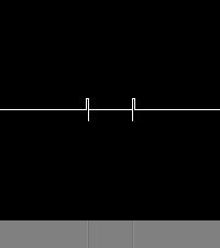
We can use a sharper divergence:
call %PICTBAT%shpDiv spm_xf.png spm_xf_div2.miff %IMG7%magick ^ spm_xf_div2.miff ^ -evaluate Divide 2 ^ -evaluate Add 50%% ^ spm_xf_div2.png call %PICTBAT%xSection spm_xf_div2.png |

|
|
Poisson paste. set rfCOMP_METRIC=PAE set ppTGT_SCORE=0.001 set ppNUM_STEPS=1000 call %PICTBAT%poissonPaste ^ spm_xb.png spm_xf.png spm_xm.png ^ spm_xout3g2.png . spm_xf_div2.miff call %PICTBAT%xSection spm_xout3g2.png 0 00:00:31 rfmsITER=9000 |

|
I have experimented with successive over-relaxation in an attempt at increasing performance. See Wikikpedia: Successive over-relaxation. This calculates each new value as a blended average of the old value and the calculated new mean:
v' = (1-w)*v + w*f(v)
Where w is the relaxation factor, usually 0 < w <= 2.
However, this only improves performance by up to 16%, and only gives that when w is carefully (manually) chosen, and the optimum w depends on the input. When w is wrong for the image, it can halve the performance, or fail to converge.
There might be a large mosaic of photographs in an irregular grid, where a small number are known to be "correct", with a requirement to adjust all the others to create a smooth final result. There could be millions of images, each with millions of pixels. Applications include aerial, satellite and drone photography, and panoramas.
A possible approach is:
After I wrote this page in 2017, IM has implemented operations "-compose seamless-blend -composite" and "-compose saliency-blend -composite". These are documented in Forum: Seamless Blending and Saliency Blending.
For both methods, three numbers can be given in "-define compose:arg=". These are:
The last is relevant only when "-verbose" is in effect.
%IMG7%magick ^
  -verbose ^
  spm_back_crp.jpg ^
  %BEAR% ^
  %MASK% ^
  -alpha off ^
  -define compose:args=5000x0.00001+500 ^
  -compose seamless-blend -composite ^
  -depth 16 ^
  spm_biw.png
This is very close to the result spm_bear_adj.png above. |
|
We do a Poisson-paste with an Inner Dirichlet Boundary, using spm_bear_sm.png. We need a black shape on a white background, so we negate the image.
set IDB=spm_bear_sm.png %IMG7%magick ^ -verbose ^ %IDB% -negate +write mpr:IDB +delete ^ spm_back_crp.jpg ^ ( %BEAR% -read-mask mpr:IDB ) ^ %MASK% ^ -alpha off ^ -define compose:args=5000x0.00001+500 ^ -compose seamless-blend -composite ^ -depth 16 ^ spm_biw2.png |
|
The second example, with the Inner Dirichlet Boundary, has slightly darkened the bear (towards its original colour), but not as much as in the method shown above in the Inner Dirichlet boundary section.
Above, we showed how to make Guided gradients using low-level operations. We can do this directly with the new "-compose saliency-blend -composite" operation.
%IMG7%magick ^ %WALL% %SCRIBBLE% %WS_MASK% ^ -compose saliency-blend -composite ^ spm_salbl.png |
|
Another use for seamless-blend is "filling holes", aka "inpainting", where we expect pixels to be the average of the 4-adjacent pixels. This is true of gradient images, and cartoons between the edges, but not true of ordinary photos.
For example, sparseMap.tiff is a distortion map from Direct polar distortion: distorting from a shape to ellipse. After inverting this map, 69% of the pixels are transparent. They have "missing" colours.
|
Here is sparseMap.tiff: |

|
|
Invert it: %IM7DEV%magick ^ sparseMap.tiff ^ -process 'invdispmap' ^ +channel ^ -define quantum:format=floating-point ^ -depth 32 ^ spm_inv_map.miff |
|
|
Flatten against blue to clearly show which pixels are transparent: %IMG7%magick ^ spm_inv_map.miff ^ +channel ^ -background Blue ^ -layers Flatten ^ spm_sm_blue.jpg |
|
Fill the holes with seamless-blend:
%IMG7%magick ^
  spm_inv_map.miff ^
  +channel ^
  ( +clone -alpha extract -negate +write mpr:ALP +delete ) ^
  ( -clone 0 -alpha off -fill Black -colorize 100 ) ^
  mpr:ALP ^
  -define compose:args=10000x1e-7+100 -compose seamless_blend -composite ^
  -alpha off ^
  spm_filled_map.miff
The filled map is:
|
spm_filled_map.png: |
|
The filled map can be used like this:
%IMG7%magick ^ toes.png spm_filled_map.miff ^ -virtual-pixel None ^ -compose distort -composite ^ spm_fm_toes.png |
|
We can test that a round trip of the forwards displacement followed by the inverse displacement results in the original image.
%IMG7%magick ^ toes.png ^ sparseMap.tiff ^ -compose distort -composite ^ spm_filled_map.miff ^ -compose distort -composite ^ spm_fm_rndtrip.png |
|
The result looks okay. The displacements shrink and then enlarge, so we can't expect a perfect result. How close is it?
%IMG7%magick compare -metric RMSE toes.png spm_fm_rndtrip.png NULL:
996.271 (0.0152021)
The distortion is quite low.
These built-in methods are faster than the script-based methods shown above, partly because they don't need to read and write an image at each iteration. However, they can't be supplied with a "first guess", so we can't make a first guess from downsized inputs.
For convenience, .bat scripts are also available in a single zip file. See Zipped BAT files.
rem Seamless boundary by Poisson pasting.
rem %1 is input background (without holes)
rem %2 is input foreground, same size (relevant only when no guidance)
rem %3 is input mask, same size
rem   mask is white where we want adjusted foreground, or black for background
rem %4 is output.
rem %5 0 or 1: whether to negate the mask.
rem %6 optional guidance image
rem %7 radius of final unsharp. 0=no unsharp. Default 0.
@rem
@rem Also uses:
@rem   ppTGT_SCORE target RMSE or PAE score. [default 0.001]
@rem   ppNUM_STEPS number of iteration steps between tests. [default 100]
@rem   ppPOST processing to apply to transition area at end, eg "-unsharp 0x0.5+1+0".
@rem
@rem   rfRLX_FUNC is a relaxation function. [default: average of 4 neighbours]
@rem   rfCOMP_METRIC default RMSE. PAE is more sensitive.
@rem
@rem Updated:
@rem   24-July-2022 for IM v7.
@rem

@if "%3"=="" findstr /B "rem @rem" %~f0 & exit /B 1

@setlocal enabledelayedexpansion

@call echoOffSave

call %PICTBAT%setInOut %1 pp

set IN_A=%INFILE%
set IN_B=%2
set MASK=%3

if not "%4"=="" if not "%4"=="." set OUTFILE=%4

set NEG_MASK=%5
if "%NEG_MASK%"=="." set NEG_MASK=
if "%NEG_MASK%"=="" set NEG_MASK=0

if not %NEG_MASK%==0 if not %NEG_MASK%==1 exit /B 1

if %NEG_MASK%==0 (
  set NEG1=-negate
  set NEG2=
) else (
  set NEG1=
  set NEG2=-negate
)

set GUID=%6
if "%GUID%"=="" set GUID=.
set HAS_GUID=1
if "%GUID%"=="." set HAS_GUID=0

set UNSHP=%7
if "%UNSHP%"=="." set UNSHP=
if "%UNSHP%"=="" set UNSHP=0

if "%ppPOST%"=="" (
  set sUNSHP=
) else (
  set sUNSHP=^^^( +clone %ppPOST% ^^^) %MASK% -compose Over -composite
)

if "%ppTGT_SCORE%"=="" set ppTGT_SCORE=0.001
if "%ppNUM_STEPS%"=="" set ppNUM_STEPS=100

set TMPDIR=\temp\
set TMP_APPRX=%TMPDIR%pp_tmp_apprx.miff
set TMP1=%TMPDIR%pp_tmp1.miff
set TMP2=%TMPDIR%pp_tmp2.miff

:: Provide a first approximation: the background over the foreground.
:: However, this seems to make performance worse.
:: %IMG7%magick ^
::   %IN_B% ^
::   %IN_A% ^
::   -compose Over -composite ^
::   %TMP_APPRX%
set TMP_APPRX=.

if %HAS_GUID%==1 (
  %IMG7%magick ^
    %IN_A% -colorspace sRGB ^
    ^( %MASK% -alpha off %NEG1% ^) ^
    -alpha off -compose CopyOpacity -composite ^
    +depth ^
    %TMP1%

  if ERRORLEVEL 1 exit /B 1
) else (
  %IMG7%magick ^
    -define compose:clamp=off ^
    %IN_A% -colorspace sRGB ^
    %IN_B% ^
    -compose Mathematics ^
      -define "compose:args=0,-0.5,0.5,0.5" -composite ^
    ^( %MASK% -alpha off %NEG1% ^) ^
    -alpha off -compose CopyOpacity -composite ^
    +depth ^
    %TMP1%

  if ERRORLEVEL 1 exit /B 1
)

call %PICTBAT%relaxFillMS ^
  %TMP1% %TMP_APPRX% %TMP2% ^
  %ppTGT_SCORE% %ppNUM_STEPS% ^
  . %GUID%

if ERRORLEVEL 1 exit /B 1

if %HAS_GUID%==1 (
  %IMG7%magick ^
    %TMP2% ^
    %sUNSHP% ^
    +depth ^
    %OUTFILE%

  if ERRORLEVEL 1 exit /B 1
) else (
  %IMG7%magick ^
    -define compose:clamp=off ^
    %IN_B% ^
    %TMP2% ^
    -compose Mathematics ^
      -define "compose:args=0,2,1,-1" -composite ^
    +depth ^
    ^( %MASK% -alpha off %NEG2% ^) ^
    -alpha off ^
    -compose CopyOpacity -composite ^
    %IN_A% ^
    +swap ^
    -compose Over -composite ^
    %sUNSHP% ^
    +depth ^
    %OUTFILE%

  if ERRORLEVEL 1 exit /B 1
)

call echoRestore

@endlocal & set ppOUTFILE=%OUTFILE%& set rfmsITER=%rfmsITER%
rem Seamless boundary by Poisson pasting, with inner Dirichlet boundary.
rem %1 is input background (without holes)
rem %2 is input foreground, same size
rem %3 is input mask, same size
rem   mask is white where we want adjusted foreground, or black for background
rem %4 inner mask, white where we want exact foreground
rem %5 is output.
rem %6 0 or 1: whether to negate the mask.
rem %7 optional guidance image
@rem
@rem Also uses:
@rem   ppTGT_SCORE target RMSE or PAE score. [default 0.001]
@rem   ppNUM_STEPS number of iteration steps between tests. [default 100]
@rem
@rem   rfRLX_FUNC is a relaxation function. [default average of 4 neighbours]
@rem   rfCOMP_METRIC default RMSE. PAE is more sensitive.
@rem
@rem Updated:
@rem   24-July-2022 for IM v7.
@rem

@if "%4"=="" findstr /B "rem @rem" %~f0 & exit /B 1

@setlocal enabledelayedexpansion

@call echoOffSave

call %PICTBAT%setInOut %1 ppi

set IN_A=%INFILE%
set IN_B=%2
set MASK=%3
set MASK_IDB=%4

if "%MASK_IDB%"=="." set MASK_IDB=

if not "%5"=="" if not "%5"=="." set OUTFILE=%5

set NEG_MASK=%6
if "%NEG_MASK%"=="." set NEG_MASK=
if "%NEG_MASK%"=="" set NEG_MASK=0

set GUID=%7
if "%GUID%"=="" set GUID=.
set HAS_GUID=1
if "%GUID%"=="." set HAS_GUID=0

if %NEG_MASK%==0 (
  set NEG1=-negate
  set NEG2=
) else (
  set NEG1=
  set NEG2=-negate
)

if "%MASK_IDB%"=="" (
  call %PICTBAT%poissonPaste ^
    %IN_A% %IN_B% %MASK%
    %OUTFILE% %NEG_MASK% %GUID%

  goto finished
)

if "%ppTGT_SCORE%"=="" set ppTGT_SCORE=0.001
if "%ppNUM_STEPS%"=="" set ppNUM_STEPS=100

set TMPDIR=\temp\
set TMP1=%TMPDIR%ppi_tmp1.miff
set TMP2=%TMPDIR%ppi_tmp2.miff

set TMP_MASK=%TMPDIR%ppi_msk.png

%IMG7%magick ^
  %MASK% ^
  ( %MASK_IDB% -alpha off -negate ) ^
  -alpha off ^
  -compose Darken -composite ^
  %TMP_MASK%

if %HAS_GUID%==1 (
  %IMG7%magick ^
    -define compose:clamp=off ^
    -compose CopyOpacity ^
    ^( %IN_A% -colorspace sRGB ^
       ^( %MASK%     -alpha off %NEG1% ^) ^
       -alpha off -composite ^
    ^) ^
    ^( %IN_B% ^
       ^( %MASK_IDB% -alpha off %NEG2% ^) ^
       -alpha off -composite ^
    ^) ^
    -compose Over -composite ^
    %TMP1%

  if ERRORLEVEL 1 exit /B 1
) else (
  %IMG7%magick ^
    -define compose:clamp=off ^
    %IN_A% -colorspace sRGB ^
    %IN_B% ^
    -compose Mathematics ^
      -define "compose:args=0,-0.5,0.5,0.5" -composite ^
    ^( +clone -fill gray^(50%%^) -colorize 100 ^) ^
    ^( %MASK_IDB% ^) ^
    -compose Over -composite ^
    +depth ^
    ^( %TMP_MASK% -alpha off %NEG1% ^) ^
    -alpha off -compose CopyOpacity -composite ^
    %TMP1%

  if ERRORLEVEL 1 exit /B 1
)

call %PICTBAT%relaxFillMS ^
  %TMP1% . %TMP2% ^
  %ppTGT_SCORE% %ppNUM_STEPS% ^
  . %GUID%

if ERRORLEVEL 1 exit /B 1

if %HAS_GUID%==1 (
  %IMG7%magick ^
    %TMP2% ^
    %OUTFILE%

  if ERRORLEVEL 1 exit /B 1
) else (
  %IMG7%magick ^
    %IN_B% ^
    %TMP2% ^
    -compose Mathematics ^
      -define "compose:args=0,2,1,-1" -composite ^
    +depth ^
    ^( %MASK% -alpha off %NEG2% ^) ^
    -alpha off ^
    -compose CopyOpacity -composite ^
    %IN_A% ^
    -colorspace sRGB ^
    +swap ^
    -compose Over -composite ^
    +depth ^
    %OUTFILE%

  if ERRORLEVEL 1 exit /B 1
)

:finished
call echoRestore

@endlocal & set ppiOUTFILE=%OUTFILE%
rem From image %1,
rem make output %2
rem that is smoothed by Poisson-pasting with guidance field
rem that is the div of the slope
rem set to zero where the slope is within %3 percent of zero.
@rem
@rem Updated:
@rem   24-July-2022 for IM v7.
@rem

@if "%1"=="" findstr /B "rem @rem" %~f0 & exit /B 1

@setlocal

@call echoOffSave

call %PICTBAT%setInOut %1 psm

if not "%2"=="." if not "%2"=="" set OUTFILE=%2

set SLP_LIM_PC=%3
if "%SLP_LIM_PC%"=="." set SLP_LIM_PC=
if "%SLP_LIM_PC%"=="" set SLP_LIM_PC=10

set TMPDIR=\temp\
set SXY=%TMPDIR%psm_sxy.miff
set SXY2=%TMPDIR%psm_sxy2.miff
set DIV=%TMPDIR%psm_div.miff
set MASK=%TMPDIR%psm_msk.miff


call %PICTBAT%slopeXY %INFILE% %SXY%

if ERRORLEVEL 1 exit /B 1

%IMG7%magick ^
  %SXY% ^
  -fuzz %SLP_LIM_PC%%% -fill Black -opaque Black ^
  -define quantum:format=floating-point ^
  -depth 32 ^
  %SXY2%

call %PICTBAT%slopeXYdiv %SXY2% %DIV%

if ERRORLEVEL 1 exit /B 1

%IMG7%magick ^
  %INFILE% ^
  -fill White -colorize 100 ^
  -gravity Center ^
  -shave 1x1 ^
  -bordercolor Black -border 1 ^
  %MASK%

call %PICTBAT%poissonPaste ^
  %INFILE% . %MASK% ^
  %OUTFILE% ^
  . %DIV%

if ERRORLEVEL 1 exit /B 1


call echoRestore

endlocal & set psmOUTFILE=%OUTFILE%
rem Given image %1,
rem makes %2
rem from connected components that are at least %3 pixels.
@rem   %3 may have suffix 'c' or '%' for percentage or 'p' for proportion of image w*h.
@rem   Default 0.
@rem
@rem Each output connected component is the mean of its input pixels.
@rem
@rem Updated:
@rem   24-July-2022 for IM v7.
@rem

@if "%1"=="" findstr /B "rem @rem" %~f0 & exit /B 1

@setlocal enabledelayedexpansion

@call echoOffSave

call %PICTBAT%setInOut %1 ccla

if not "%2"=="" if not "%2"=="." set OUTFILE=%2


set THRESH=%3
if "%THRESH%"=="." set THRESH=
if "%THRESH%"=="" set THRESH=0


set TH_LAST=%THRESH:~-1%

if "%TH_LAST%"=="^%" set TH_LAST=c

if /I "%TH_LAST%"=="c" (

  for /F "usebackq" %%L in (`%IMG7%magick identify ^
    -format "nTHRESH=%%[fx:w*h*%THRESH:~0,-1%/100]" ^
    %INFILE%`) do set %%L

) else if /I "%TH_LAST%"=="p" (

  for /F "usebackq" %%L in (`%IMG7%magick identify ^
    -format "nTHRESH=%%[fx:w*h*%THRESH:~0,-1%]" ^
    %INFILE%`) do set %%L

) else (
  set nTHRESH=%THRESH%
)

if %nTHRESH%==0 (
  set sTHRESH=
) else (
  set "sTHRESH=-define connected-components:area-threshold^=%nTHRESH%"
)


%IMG7%magick ^
  %INFILE% ^
  -define connected-components:verbose^=true ^
  -define connected-components:mean-color=true ^
  %sTHRESH% ^
  -connected-components 4 ^
  %OUTFILE%


call echoRestore

@endlocal & set cclaOUTFILE=%OUTFILE%
rem Given image %1,
rem makes %2
rem from the largest %3 connected components.
@rem
@rem For performance, use the output from connCompLimitArea.bat
@rem to reduce the number of components this script considers.
@rem (or add area parameter to this script?)
@rem
@rem When an eliminated component is adjacent to more than one other component,
@rem   it may merge with the "wrong" one.
@rem
@rem Each output connected component is the mean of its input pixels.
@rem
@rem Updated:
@rem   24-July-2022 for IM v7.
@rem   29-July-2022 Bug in "-connected-components" hinders merging. "-virtual-pixel None" may help.
@rem     Also repeating "-connected-components" with rotated image.
@rem     (See https://github.com/ImageMagick/ImageMagick/issues/5368 )
@rem


@if "%1"=="" findstr /B "rem @rem" %~f0 & exit /B 1

@setlocal enabledelayedexpansion

rem @call echoOffSave

call %PICTBAT%setInOut %1 ccln

if not "%2"=="" if not "%2"=="." set OUTFILE=%2

set NUM=%3
if "%NUM%"=="." set NUM=
if "%NUM%"=="" set NUM=1

set N_CONNECT=8
set N_CONNECT=4

goto skip1

%IMG7%magick ^
  %INFILE% ^
  -define connected-components:verbose^=true ^
  -connected-components %N_CONNECT% ^
  NULL:

:skip1

set sKEEP=
set CNT=1
set LIM_AREA=0
set nTHRESH=
for /F "usebackq skip=1 tokens=4" %%A in (`%IMG7%magick ^
  %INFILE% ^
  -define connected-components:verbose^=true ^
  -connected-components %N_CONNECT% ^
  NULL:`) do (
  rem echo %%A
  if !CNT!==%NUM% set nTHRESH=%%A
  set /A CNT+=1
)

echo %0: nTHRESH=%nTHRESH%

if "%nTHRESH%"=="" (
  echo %0: Found CNT=%CNT%, not NUM=%NUM%
  exit /B 1
)

%IMG7%magick ^
  %INFILE% ^
  -virtual-pixel None ^
  -define connected-components:verbose=true ^
  -define connected-components:mean-color=true ^
  -define connected-components:area-threshold=%nTHRESH% ^
  -connected-components %N_CONNECT% ^
  -rotate 180 ^
  -connected-components %N_CONNECT% ^
  -rotate -180 ^
  %OUTFILE%

goto end


set sKEEP=
set CNT=1
set LIM_AREA=0
for /F "usebackq skip=1 tokens=1 delims=: " %%A in (`%IMG7%magick ^
  %INFILE% ^
  -define connected-components:verbose^=true ^
  -connected-components %N_CONNECT% ^
  NULL:`) do (
  rem echo %%A
  if !CNT! LEQ %NUM% set sKEEP=!sKEEP!,%%A
  set /A CNT+=1
)

echo sKEEP=%sKEEP%

rem Remove initial comma
set sKEEP=%sKEEP:~1%

echo sKEEP=%sKEEP%


:: FIXME: No, this makes the others transparent!!
:: We need to find the limiting area.

set UNIQ=\temp\ccln_uniq.png

%IMG7%magick ^
  %INFILE% ^
  -define connected-components:verbose^=true ^
  -define connected-components:keep=%sKEEP% ^
  -define connected-components:mean-color=true ^
  -connected-components %N_CONNECT% ^
  -unique-colors ^
  %UNIQ%

%IMG7%magick identify %UNIQ%

:end

call echoRestore

@endlocal & set cclnOUTFILE=%OUTFILE%
rem Given images %1 and %2
rem %3 is an offset for #2 with respect to #1
rem makes output %4
rem that is #2 composited over #1, and colour-corrected.
@rem
@rem Also uses:
@rem   cc2DRAW if provided, draws this in gray before relax-fill.
@rem
@rem
@rem Updated:
@rem   24-July-2022 for IM v7.
@rem


@if "%3"=="" findstr /B "rem @rem" %~f0 & exit /B 1

@setlocal enabledelayedexpansion

@call echoOffSave

set INFILE1=%1
set INFILE2=%2
set OFFS_2=%3
set OUTFILE=%4

set TMP_FILE=\temp\cc2.miff

if "%cc2DRAW%"=="" (
  set sDRAW=
) else (
  set sDRAW=-fill gray^(50%%^) -stroke gray^(50%%^) -draw "%cc2DRAW%"
)

%IMG7%magick ^
  ( %INFILE1% +write mpr:IN1 ) ^
  -fill gray(50%%) -colorize 100 ^
  -fuzz 0.1%% ^
  ( %INFILE2% +write mpr:IN2 ^
    -fill Red -colorize 100 ^
    -shave 1x1 -bordercolor gray(50%%) -border 1 ^
    -repage %OFFS_2% ^
  ) ^
  -background Black ^
  -compose Plus -layers merge +repage ^
  -fill Black +opaque White ^
  -crop %OFFS_2% +repage ^
  +write mpr:LMASK ^
  +delete ^
  mpr:IN1 ^
  ( mpr:IN2 -repage %OFFS_2% ) ^
  -compose Mathematics ^
    -define compose:args=0,-0.5,0.5,0.5 ^
  -background None ^
  -layers merge ^
  -crop %OFFS_2% +repage ^
  mpr:LMASK ^
  -alpha off ^
  -compose CopyOpacity -composite ^
  %sDRAW% ^
  %TMP_FILE%

if ERRORLEVEL 1 exit /B 1

rem Relax-fill to get an adjustment image:

call %PICTBAT%relaxFillMS ^
  %TMP_FILE% . %TMP_FILE% ^
  1e-6 1000

if ERRORLEVEL 1 exit /B 1


:skip

rem Add the adjustment image to #2:

%IMG7%magick ^
  %INFILE2% ^
  %TMP_FILE% ^
  -compose Mathematics ^
    -define compose:args=0,2,1,-1 -composite ^
  -repage %OFFS_2% ^
  %INFILE1% ^
  +swap ^
  -background None -compose Over ^
  -layers merge +repage ^
  %OUTFILE%

if ERRORLEVEL 1 exit /B 1

endlocal& set cc2OUTFILE=%OUTFILE%
rem From image %1,
rem make horizontal cross-section.
@rem
@rem Updated:
@rem   24-July-2022 for IM v7.
@rem

@if "%1"=="" findstr /B "rem @rem" %~f0 & exit /B 1

@setlocal

@call echoOffSave

call %PICTBAT%setInOut %1 xs

if not "%2"=="" if not "%2"=="." set OUTFILE=%2

set WW=
for /F "usebackq" %%L in (`%IMG7%magick identify ^
  -format "WW=%%w\nHH=%%h\nW_2=%%[fx:int(w/2)]\nH_2=%%[fx:int(h/2)]" ^
  %INFILE%`) do set %%L
if "%WW%"=="" exit /B 1

set TMP=%TEMP%\xs.miff

%IMG7%magick ^
  %INFILE% ^
  -crop %WW%x1+0+%H_2% +repage ^
  %TMP%

call %PICTBAT%graphLineCol %TMP% . . . %OUTFILE%

call echoRestore

endlocal & set xsOUTFILE=%OUTFILE%
All images on this page were created by the commands shown, using:
%IMG7%magick identify -version
Version: ImageMagick 7.1.1-15 Q16-HDRI x64 a0a5f3d:20230730 https://imagemagick.org
Copyright: (C) 1999 ImageMagick Studio LLC
License: https://imagemagick.org/script/license.php
Features: Cipher DPC HDRI OpenCL OpenMP(2.0)
Delegates (built-in): bzlib cairo freetype gslib heic jng jp2 jpeg jxl lcms lqr lzma openexr pangocairo png ps raqm raw rsvg tiff webp xml zip zlib
Compiler: Visual Studio 2022 (193532217)
To improve internet download speeds, some images may have been automatically converted (by ImageMagick, of course) from PNG or TIFF or MIFF to JPG.
Source file for this web page is seamlpm.h1. To re-create this web page, run "procH1 seamlpm".
This page, including the images except where shown otherwise, is my copyright. Anyone is permitted to use or adapt any of the code, scripts or images for any purpose, including commercial use.
Anyone is permitted to re-publish this page, but only for non-commercial use.
Anyone is permitted to link to this page, including for commercial use.
Page version v2.0 25-June-2017.
Page created 23-Oct-2023 04:27:03.
Copyright © 2023 Alan Gibson.