snibgo's ImageMagick pages
Clut cookbook
Many methods for creating Nx1 Colour Look Up Tables.
ImageMagick uses a clut (Colour Look Up Table) to transform the colours of an image, channel by channel. From the input image, a red channel pixel value is used as an index into the clut image. The value in the red channel of the clut image is used as the new value for the red channel of the output image. The process is repeated for green and blue.
A clut can also be thought of as variation of an absolute displacement map.
ImageMagick accesses a clut file along its diagonal, from top-left to bottom-right, so it can be two-dimensional. As a clut file represents a single dimension, this is a waste of space and processing power. So a clut file is generally either vertical (read from the top down, width=1) or horizontal (read from left to right, height=1).
My clut files have one dimension, usually horizontal. They are often monochrome (gray, with no colour).
For convenience in the cookbook, sizes are small, eg 1x100. In practice, they are often larger such as 1x1000 or 1x65536. (Currently, there is no point in using larger cluts.)
As they are only one pixel wide or high, they are difficult to see and I don't bother to include them as images on this page. Instead I put them through a script that makes an image that shows both the tonal values and the numerical values as a graph, or shows a graph of the three colour channels plus a sample. See
Scripts below. In the graphs, the x-axis represents the input to a function and the y-axis represents the output.
See also
Log cluts and
Non-absolute cluts.
An "-fx" expression used to be interpreted for every pixel, so it was slow. Since about v7.1.0-21 interpretation occurs only once, with translation to Reverse Polish Notation, greatly increasing performance. Cluts usually have few pixels so speed is not an issue. An "-fx" is easy to understand.
If we start wth a gradient, u will range from zero to one.
|
Linear
%IMG7%magick -size 1x100 gradient: -rotate 90 ^
  -fx "u" ^
  cl_fx1.png
call %PICTBAT%graph1d cl_fx1.png
|

|
|
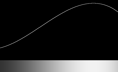
Half a cycle of sine, sin(x) where 0<x<pi (radians), 0<x<180°
%IMG7%magick -size 1x100 gradient: -rotate 90 ^
  -fx "sin(pi*u)" ^
  cl_fx2.png
call %PICTBAT%graph1d cl_fx2.png
|

|
|
Four cycles of sine, sin(x) where 0<x<8.pi (radians)
%IMG7%magick -size 1x100 gradient: -rotate 90 ^
  -fx "sin(8*pi*u)/2+0.5" ^
  cl_fx3.png
call %PICTBAT%graph1d cl_fx3.png
|

|
|
Squish function; squish(x)=1.0/(1.0+exp(-x))
%IMG7%magick -size 1x100 gradient: -rotate 90 ^
  -fx "squish(u)" ^
  cl_fx4.png
call %PICTBAT%graph1d cl_fx4.png
|

|
|
Flattened ends
%IMG7%magick -size 1x100 gradient: -rotate 90 ^
  -fx "min(max(u,0.2),0.7)" ^
  cl_fx5.png
call %PICTBAT%graph1d cl_fx5.png
|

|
|
Flattened middle
%IMG7%magick -size 1x100 gradient: -rotate 90 ^
  -fx "u<0.2?u:u>0.7?u:0.5" ^
  cl_fx5a.png
call %PICTBAT%graph1d cl_fx5a.png
|

|
|
Quarter circle
%IMG7%magick -size 1x100 gradient: -rotate 90 ^
  -fx "sqrt(u*(2-u))" ^
  cl_fx6.png
call %PICTBAT%graph1d cl_fx6.png
|

|
|
Half circle
%IMG7%magick -size 1x100 gradient: -rotate 90 ^
  -fx "sqrt(u*(4-u*4))" ^
  cl_fx7.png
call %PICTBAT%graph1d cl_fx7.png
|

|
|
Arctan. See
De-barrel distortion.
%IMG7%magick -size 1x100 gradient: -rotate 90 ^
  -fx "atan(u*Pi)/atan(Pi)" ^
  cl_atan.png
call %PICTBAT%graph1d cl_atan.png
|

|
|
Arctan2.
%IMG7%magick -size 1x100 gradient: -rotate 90 ^
  -fx "atan2(u*Pi,1)/atan(Pi,1)" ^
  cl_atan2.png
call %PICTBAT%graph1d cl_atan2.png
|
|
|
Reverse the slope after it peaks at white.
Initial slope has gradient 1.5, so peak is at 1/1.5 = 2/3.
%IMG7%magick -size 1x100 gradient: -rotate 90 ^
  -fx "V=u*1.5;V<1?V:2-V" ^
  cl_fx8.png
call %PICTBAT%graph1d cl_fx8.png
|

|
|
Clut width WW, zero at ends, and white at PK.
set WW=100
set PK=20

set P1=%PK%/%WW%
set S1=%WW%/%PK%
set S2=%WW%/(%PK%-%WW%)

%IMG7%magick -size 1x%WW% gradient: -rotate 90 ^
  -fx "u<%P1%?u*%S1%:1+(u-%P1%)*%S2%" ^
  cl_peak.png
call %PICTBAT%graph1d cl_peak.png
|

|
|
The same, but PR is fraction of width.
set PR=0.20

%IMG7%magick -size 1x100 gradient: -rotate 90 ^
  -fx "u<%PR%?u/%PR%:1+(u-%PR%)/(%PR%-1)" ^
  cl_peak1.png
call %PICTBAT%graph1d cl_peak1.png
|

|
|
As previous, but smoother.
%IMG7%magick ^
  cl_peak.png ^
  -function sinusoid 0.5,-90,0.5,0.5 ^
  cl_peak2.png
call %PICTBAT%graph1d cl_peak2.png
|

|
|
Shark fin with peak at x=0.5.
%IMG7%magick -size 1x100 gradient: -rotate 90 ^
  -fx "u<0.5 ? u*2 : exp(-(u-0.5)*10)" ^
  cl_shfin1.png
call %PICTBAT%graph1d cl_shfin1.png
|
|
|
Shark fin with peak at x=0.3.
set Pk=0.3

%IMG7%magick -size 1x100 gradient: -rotate 90 ^
  -fx "u<%Pk% ? u/%Pk% : exp(-(u-%Pk%)*10)" ^
  cl_shfin2.png
call %PICTBAT%graph1d cl_shfin2.png
|
|
|
Linear transformation such that X1 becomes Y1.
set X1=0.2
set Y1=0.6

%IMG7%magick ^
  -size 1x100 gradient: -rotate 90 ^
  -fx "u<%X1%?u*%Y1%/%X1%:%Y1%+(u-%X1%)*(1-%Y1%)/(1-%X1%)" ^
  cl_linxy.png

call %PICTBAT%graph1d cl_linxy.png
|

|
|
Staircase with 6 steps. One is black but none is white.
%IMG7%magick -size 1x100 gradient: -rotate 90 ^
  -fx "int(u*6)/6" ^
  cl_fx9.png
call %PICTBAT%graph1d cl_fx9.png
|

|
|
Staircase with 6 steps, including black and white.
For this, we reduce the numerator by one.
%IMG7%magick -size 1x100 gradient: -rotate 90 ^
  -fx "int(u*6)/5" ^
  cl_fx10.png
call %PICTBAT%graph1d cl_fx10.png
|

|
|
Staircase by posterize with 6 steps.
%IMG7%magick -size 1x100 gradient: -rotate 90 ^
  +dither -posterize 6 ^
  cl_post1.png
call %PICTBAT%graph1d cl_post1.png
|

|
|
Staircase by posterize with 6 steps, default dithering.
%IMG7%magick -size 1x100 gradient: -rotate 90 ^
  ( +clone ^
    +dither -posterize 6 -write mpr:STEPS +delete ^
  ) ^
  -remap mpr:STEPS ^
  cl_post2.png
call %PICTBAT%graph1d cl_post2.png
|

|
|
Staircase by posterize with 6 steps, Riemersma dithering.
%IMG7%magick -size 1x100 gradient: -rotate 90 ^
  ( +clone ^
    +dither -posterize 6 -write mpr:STEPS +delete ^
  ) ^
  -dither Riemersma ^
  -remap mpr:STEPS ^
  cl_post3.png
call %PICTBAT%graph1d cl_post3.png
|

|
|
Staircase by posterize with 6 steps, Floyd-Steinberg dithering.
%IMG7%magick -size 1x100 gradient: -rotate 90 ^
  ( +clone ^
    +dither -posterize 6 -write mpr:STEPS +delete ^
  ) ^
  -dither FloydSteinberg ^
  -remap mpr:STEPS ^
  cl_post4.png
call %PICTBAT%graph1d cl_post4.png
|

|
|
Random threshold.
%IMG7%magick -size 1x100 gradient: -rotate 90 ^
  -seed 1234 ^
  -random-threshold 25%%,75%% ^
  cl_rt1.png
call %PICTBAT%graph1d cl_rt1.png
|

|
"-fx" is slower than simpler operations. For increased performance on large input images, or multiple images, we can create a clut file and apply that to each input. For example:
|
Staircase with 6 steps, including black and white.
%IMG7%magick -size 1x65535 gradient: -rotate 90 ^
  -fx "int(u*6)/5" ^
  cl_st6_cl.png

%IMG7%magick -size 1x100 gradient: -rotate 90 ^
  cl_st6_cl.png -clut ^
  cl_st6.png
call %PICTBAT%graph1d cl_st6.png
|

|
See
Luminous Landscape forum: equation for a contrast curve.
We create a sigmoidal curve with inflection at (a,b), slope s at ends, and contrast strength E. The result is a pair of power curves, joined together at (a,b).
set a=0.4
set b=0.5
set s=0.9
set E=3

set a1=(1-%a%)
set s1=(1-%s%)
set sa=%s%*%a%
set sa1=%s%*%a1%
set LR=log(%b%)/log(%a%)
set LR1=log(1-%b%)/log(1-%a%)

for /F "usebackq" %%L in (`%IMG7%magick identify
  -precision 15 ^
  -format "a1=%%[fx:%a1%]\ns1=%%[fx:%s1%]\nsa=%%[fx:%sa%]\nsa1=%%[fx:%sa1%]" ^
  xc:`) do set %%L

for /F "usebackq" %%L in (`%IMG7%magick identify
  -precision 15 ^
  -format "LR=%%[fx:%LR%]\nLR1=%%[fx:%LR1%]" ^
  xc:`) do set %%L

%IMG7%magick -size 1x100 gradient: -rotate 90 ^
  -fx "u<%a%?pow(%s1%*u+%sa%*pow(u/%a%,%E%),%LR%):1-pow(%s1%*(1-u)+%sa1%*pow((1-u)/%a1%,%E%),%LR1%)" ^
  cl_fxsig.png
call %PICTBAT%graph1d cl_fxsig.png
|

|
For the first half of the curve, where u<a, the formula is:
y = ( (1-s)*u + s*a* (u/a)E )log(b)/log(a)
The second half, where u>=a, is similar:
y = 1 - ( (1-s)*(1-u) + s*(1-a)* ((1-u)/(1-a))E )log(1-b)/log(1-a)
When s==1:
y = ( a * (u/a)E )log(b)/log(a)
This method may be useful, so we put it in a script,
mSigClut.bat.
call %PICTBAT%mSigClut cl_fxsig2.png 256 0.4 0.5 0.9 3

call %PICTBAT%graph1d cl_fxsig2.png
|

|
call %PICTBAT%mSigClut cl_fxsig3.png 256 0.5 0.5 1 3

call %PICTBAT%graph1d cl_fxsig3.png
|

|
call %PICTBAT%mSigClut cl_fxsig4.png 256 0.5 0.5 1 0.33333

call %PICTBAT%graph1d cl_fxsig4.png
|

|
call %PICTBAT%mSigClut cl_fxsig5.png 256 0.3 0.3 1 0.33333

call %PICTBAT%graph1d cl_fxsig5.png
|

|
call %PICTBAT%mSigClut cl_fxsig6.png 256 0.3 0.7 1 0.33333

call %PICTBAT%graph1d cl_fxsig6.png
|

|
call %PICTBAT%mSigClut cl_fxsig7.png 256 0.5 0.5 1 4

call %PICTBAT%graph1d cl_fxsig7.png
|

|
call %PICTBAT%mSigClut cl_fxsig8.png 256 0.5 0.5 0.5 4

call %PICTBAT%graph1d cl_fxsig8.png
|

|
call %PICTBAT%mSigClut cl_fxsig9.png 256 0.5 0.5 0.5 10

call %PICTBAT%graph1d cl_fxsig9.png
|
|
call %PICTBAT%mSigClut cl_fxsig10.png 256 0.5 0.5 0.1 10

call %PICTBAT%graph1d cl_fxsig10.png
|

|
call %PICTBAT%mSigClut cl_fxsig11.png 256 0.5 0.5 0.1 100

call %PICTBAT%graph1d cl_fxsig11.png
|

|
A special case of this curve passes through (0,0) and (1,1) and a fulcrum (F,F) where 0<F<1, with "contrast" G at (F,F), with s=0.5. The two curves simplify to:
Where v <= F:
v' = 0.5*v+0.5*F*pow(v/F,G)

Where v >= F:
v' = 1-(0.5*(1-v)+0.5*(1-F)*pow((1-v)/(1-F),G))
The gradient dv'/dv at (F,F) is (G+1)/2. Or, if we require a gradient dv'/dv, then G = 2 * (dv'/dv) - 1.
The script
fulcrum.bat implements this.
|
Example with G>1:
%IMG7%magick ^
  -size 1x256 gradient: -rotate 90 ^
  cl_siggrad.png

call %PICTBAT%fulcrum ^
  cl_siggrad.png cl_siggrad_out.png ^
  0.2 3.5

call %PICTBAT%graph1d cl_siggrad_out.png
|

|
|
Example with G<1:
%IMG7%magick ^
  -size 1x256 gradient: -rotate 90 ^
  cl_siggrad.png

call %PICTBAT%fulcrum ^
  cl_siggrad.png cl_siggrad_out2.png ^
  0.2 0.4

call %PICTBAT%graph1d cl_siggrad_out2.png
|

|
For some purposes we can remove the v/2 term and the 0.5 factor, resulting in:
Where v <= F:
v' = F*pow(v/F,G)

Where v >= F:
v' = 1-((1-F)*pow((1-v)/(1-F),G))
The gradient dv'/dv at (0,0) and (1,1) is zero, so we have zero contrast at black and white. The gradient at (F,F) is G. This is implemented in the script
fulcrum2.bat.
|
Example with G>1:
call %PICTBAT%fulcrum2 ^
  cl_siggrad.png cl_ful2_out.png ^
  0.2 3.5

call %PICTBAT%graph1d cl_ful2_out.png
|

|
|
Example with G<1:
call %PICTBAT%fulcrum2 ^
  cl_siggrad.png cl_ful2_out2.png ^
  0.2 0.4

call %PICTBAT%graph1d cl_ful2_out2.png
|

|
It can be shown that when G>1, the slope is at a maximum when v=F. Similarly when G<1, the slope is at a minimum when v=F.
On the other hand, we can generalise the power-power curve by inserting a linear portion in the middle, with the script
mPowLinPow.bat. The result is a power curve from (0,0) to (x0,y0), then linear to (x1,y1), then a second power curve to (1,1). If x0>=x1, the script will reverse the two locations. The gradient can be negative, in which case it is from (0,1) to (1,0), and y0 will be greater than y1. This is a form of filmic curve.
The gradient of the straight line portion is:
E = (y1-y0) / (x1-x0)
This is also the required gradient of the power curves where they meet the linear portion.
For simplicity we use a simple power curve at each end:
y = a * xp
At the first transition (x0,y0):
y0 = a * x0p
a = y0 / x0p
The gradient E at (x0,y0) is:
E = a * p * x0p-1
  = a * p * x0p/x0
So:
E = (y0 / x0p) * p * x0p / x0
  = y0 * p / x0
p = E * x0 / y0
So we can calculate p and a from x0, y0 and E. The second power curve is similar.
call %PICTBAT%mPowLinPow ^
  cl_plp_1.png 256

call %PICTBAT%graph1d cl_plp_1.png
|

|
call %PICTBAT%mPowLinPow ^
  cl_plp_2.png 256 "0.1,0.2" "0.9,0.8"

call %PICTBAT%graph1d cl_plp_2.png
|

|
call %PICTBAT%mPowLinPow ^
  cl_plp_2a.png 256 "0.6,0.2" "0.9,0.8"

call %PICTBAT%graph1d cl_plp_2a.png
|

|
|
When the points coincide, we get:
call %PICTBAT%mPowLinPow ^
  cl_plp_3.png 256 "0.3,0.6" "0.3,0.6"

call %PICTBAT%graph1d cl_plp_3.png
|

|
|
When y0>y1, we get a full reversal:
call %PICTBAT%mPowLinPow ^
  cl_plp_4.png 256 "0.1,0.8" "0.9,0.2"

call %PICTBAT%graph1d cl_plp_4.png
|

|
|
Another reversal:
call %PICTBAT%mPowLinPow ^
  cl_plp_4a.png 256 "0.2,0.6" "0.7,0.3"

call %PICTBAT%graph1d cl_plp_4a.png
|

|
call %PICTBAT%mPowLinPow ^
  cl_plp_5.png 256 "0.2,0.4" "0.6,0.8"

call %PICTBAT%graph1d cl_plp_5.png
|

|
call %PICTBAT%mPowLinPow ^
  cl_plp_6.png 256 "0.2,0.4" "0.6,0.6"

call %PICTBAT%graph1d cl_plp_6.png
|

|
The curve might or might not pass through any point (F,F) where 0<F<1.
Instead of using the end-points of the linear portion, the script
mPlpFulc.bat uses:
- a fulcrum location (Fx,Fy) within the linear portion, where 0<=Fx,Fy<=1;
- the gradient G of the linear portion, where -∞<=G<=+∞, zero is flat, one for gradient parallel to y=x;
- and the length of the linear portion as a proportion of the total length, where length>=0.
The script calculates the ends of the linear portion, (x0,y0) and (x1,y1), and calls mPowLinPow.bat.
The proportion is in the direction of the y-axis for steep gradients, otherwise in the direction of the x-axis.
|
Default length
call %PICTBAT%mPlpFulc ^
  cl_plpf_1.png 256 "0.3,0.4" 0.5

call %PICTBAT%graph1d cl_plpf_1.png
|

|
|
Longer length
call %PICTBAT%mPlpFulc ^
  cl_plpf_2.png 256 "0.3,0.4" 0.5 0.8

call %PICTBAT%graph1d cl_plpf_2.png
|

|
|
Shorter length
call %PICTBAT%mPlpFulc ^
  cl_plpf_3.png 256 "0.3,0.4" 0.5 0.1

call %PICTBAT%graph1d cl_plpf_3.png
|

|
|
Zero length
call %PICTBAT%mPlpFulc ^
  cl_plpf_4.png 256 "0.3,0.4" 0.5 0

call %PICTBAT%graph1d cl_plpf_4.png
|

|
|
Steeper gradient, default length
call %PICTBAT%mPlpFulc ^
  cl_plpf_5.png 256 "0.3,0.4" 3.0

call %PICTBAT%graph1d cl_plpf_5.png
|

|
|
Shallower gradient, default length
call %PICTBAT%mPlpFulc ^
  cl_plpf_6.png 256 "0.3,0.4" 0.1

call %PICTBAT%graph1d cl_plpf_6.png
|

|
|
Zero gradient, default length
call %PICTBAT%mPlpFulc ^
  cl_plpf_7.png 256 "0.3,0.4" 0

call %PICTBAT%graph1d cl_plpf_7.png
|

|
|
Negative gradient, default length
call %PICTBAT%mPlpFulc ^
  cl_plpf_8.png 256 "0.3,0.4" -1.5

call %PICTBAT%graph1d cl_plpf_8.png
|

|
|
Linear
%IMG7%magick -size 1x100 gradient: -rotate 90 ^
  cl_g.png
call %PICTBAT%graph1d cl_g.png
|

|
|
Sigmoid
%IMG7%magick -size 1x100 gradient: -rotate 90 ^
  -sigmoidal-contrast 5,50%% ^
  cl_sig1.png
call %PICTBAT%graph1d cl_sig1.png
|

|
|
Sigmoid with greatest slope at x=25%.
%IMG7%magick -size 1x100 gradient: -rotate 90 ^
  -sigmoidal-contrast 5,25%% ^
  cl_sig2.png
call %PICTBAT%graph1d cl_sig2.png
|

|
|
Sigmoid with greatest slope at x=75%.
%IMG7%magick -size 1x100 gradient: -rotate 90 ^
  -sigmoidal-contrast 5,75%% ^
  cl_sig2a.png
call %PICTBAT%graph1d cl_sig2a.png
|

|
|
Inverse sigmoid, with least slope at x=25%.
%IMG7%magick -size 1x100 gradient: -rotate 90 ^
  +sigmoidal-contrast 5,25%% ^
  cl_sig3.png
call %PICTBAT%graph1d cl_sig3.png
|

|
|
Inverse sigmoid, with least slope at x=75%.
%IMG7%magick -size 1x100 gradient: -rotate 90 ^
  +sigmoidal-contrast 5,75%% ^
  cl_sig3a.png
call %PICTBAT%graph1d cl_sig3a.png
|

|
|
-Level. The arguments specify the x-values where the line intersects y=0 and y=100%.
%IMG7%magick -size 1x100 gradient: -rotate 90 ^
  -level 10%%,70%% ^
  cl_lev1.png
call %PICTBAT%graph1d cl_lev1.png
|

|
|
+Level. The arguments specify the y-values where the line intersects x=0 and x=100%.
%IMG7%magick -size 1x100 gradient: -rotate 90 ^
  +level 10%%,70%% ^
  cl_lev2.png
call %PICTBAT%graph1d cl_lev2.png
|

|
|
-Level with arguments outside 0 to 100%.
%IMG7%magick -size 1x100 gradient: -rotate 90 ^
  -level -50%%,150%% ^
  cl_lev3.png
call %PICTBAT%graph1d cl_lev3.png
|

|
|
Flat, ramp up, level, ramp down, flat.
%IMG7%magick -size 1x100 gradient: -rotate 90 ^
  -channel RGB ^
  -range-threshold "20,50,60,90%%" ^
  +channel ^
  cl_rngth1.png
call %PICTBAT%graph1d cl_rngth1.png
|

|
|
Ramp up to white at 20%, then down.
%IMG7%magick -size 1x100 gradient: -rotate 90 ^
  -channel RGB ^
  -range-threshold "0,20,20,100%%" ^
  +channel ^
  cl_rngth2.png
call %PICTBAT%graph1d cl_rngth2.png
|

|
|
Flattened top.
Cap each channel at 70%.
%IMG7%magick -size 1x100 gradient: -rotate 90 ^
  -channel RGB ^
  -evaluate Min 70%% ^
  +channel ^
  cl_flattop.png
call %PICTBAT%graph1d cl_flattop.png
|

|
|
Flattened middle.
For the region centred on 50% plus or minus 20% (ie from 30% to 70%), make it 15% gray.
%IMG7%magick -size 1x100 gradient: -rotate 90 ^
  -fuzz 20%% -fill gray(15%%) -opaque gray(50%%) ^
  cl_flat1.png
call %PICTBAT%graph1d cl_flat1.png
|

|
|
Flattened middle.
For the region centred on 50% plus or minus 20% (ie from 30% to 70%), make it 50% gray.
%IMG7%magick -size 1x100 gradient: -rotate 90 ^
  -fuzz 20%% -fill gray(50%%) -opaque gray(50%%) ^
  cl_flat1a.png
call %PICTBAT%graph1d cl_flat1a.png
|

|
|
Flattened outer. As above but set everything outside the region.
%IMG7%magick -size 1x100 gradient: -rotate 90 ^
  -fuzz 20%% -fill gray(15%%) +opaque gray(50%%) ^
  cl_flat2.png
call %PICTBAT%graph1d cl_flat2.png
|

|
|
Flattened middle using fx.
%IMG7%magick -size 1x100 gradient: -rotate 90 ^
  -fx "u>0.3&&u<0.7?0.15:u" ^
  cl_flat_fx.png
call %PICTBAT%graph1d cl_flat_fx.png
|

|
|
Threshold black.
%IMG7%magick -size 1x100 gradient: -rotate 90 ^
  -black-threshold 40%% ^
  cl_thb.png
call %PICTBAT%graph1d cl_thb.png
|

|
|
Threshold white.
%IMG7%magick -size 1x100 gradient: -rotate 90 ^
  -white-threshold 40%% ^
  cl_thw.png
call %PICTBAT%graph1d cl_thw.png
|

|
|
Threshold a middle range. Turn 70% plus or minus 20%, ie 50% to 90%, to white.
By turning pixels outside the range to black, we avoid difficulties with input white pixels.
%IMG7%magick -size 1x100 gradient: -rotate 90 ^
  -fuzz 20%% ^
  -fill Black +opaque gray(70%%) ^
  -fuzz 0 ^
  -fill White +opaque Black ^
  cl_thm.png
call %PICTBAT%graph1d cl_thm.png
|

|
|
Threshold a middle range, using transparency.
%IMG7%magick -size 1x100 gradient: -rotate 90 ^
  -alpha Opaque ^
  -fuzz 20%% -transparent gray(70%%) ^
  -channel RGB -evaluate set 0 +channel ^
  -background White -layers Flatten ^
  cl_thm2.png
call %PICTBAT%graph1d cl_thm2.png
This is slower than the previous method ...
|

|
|
... but is readily expanded for multiple ranges.
%IMG7%magick -size 1x100 gradient: -rotate 90 ^
  -alpha Opaque ^
  -fuzz 5%% -transparent gray(25%%) ^
  -fuzz 20%% -transparent gray(70%%) ^
  -channel RGB -evaluate set 0 +channel ^
  -background White -layers Flatten ^
  cl_thm3.png
call %PICTBAT%graph1d cl_thm3.png
|
|
|
One cycle of sine.
%IMG7%magick -size 1x100 gradient: -rotate 90 ^
  -evaluate sin 1 ^
  cl_sin1.png
call %PICTBAT%graph1d cl_sin1.png
|

|
|
One cycle of cosine.
%IMG7%magick -size 1x100 gradient: -rotate 90 ^
  -evaluate cos 1 ^
  cl_cos1.png
call %PICTBAT%graph1d cl_cos1.png
|

|
|
Half a cycle of cosine.
%IMG7%magick -size 1x100 gradient: -rotate 90 ^
  -evaluate cos 0.5 ^
  cl_cos2.png
call %PICTBAT%graph1d cl_cos2.png
|

|
|
Four cycles of sine.
%IMG7%magick -size 1x100 gradient: -rotate 90 ^
  -evaluate sin 4 ^
  cl_sin4.png
call %PICTBAT%graph1d cl_sin4.png
|

|
|
Half a cycle of sine.
%IMG7%magick -size 1x100 gradient: -rotate 90 ^
  -evaluate sin 0.5 ^
  cl_sin05.png
call %PICTBAT%graph1d cl_sin05.png
|

|
|
Half a cycle of sine, offset by -90°.
Gradient is +1 at centre (provided w = pi * h) and zero at ends.
y = amp * sin(2*pi* (freq * x + phase / 360)) + bias
set FREQ=0.5
set PHASE=-90
set AMP=0.5
set BIAS=0.5
%IMG7%magick -size 1x100 gradient: -rotate 90 ^
  -function sinusoid %FREQ%,%PHASE%,%AMP%,%BIAS% ^
  cl_sinus1.png
call %PICTBAT%graph1d cl_sinus1.png
|

|
|
Two cycles of sine, offset by +90°.
set FREQ=2
set PHASE=90
set AMP=0.5
set BIAS=0.5
%IMG7%magick -size 1x100 gradient: -rotate 90 ^
  -function sinusoid %FREQ%,%PHASE%,%AMP%,%BIAS% ^
  cl_sinus2.png
call %PICTBAT%graph1d cl_sinus2.png
|

|
|
Quarter cycle of sine.
set FREQ=0.25
set PHASE=0
set AMP=1
set BIAS=0
%IMG7%magick -size 1x100 gradient: -rotate 90 ^
  -function sinusoid %FREQ%,%PHASE%,%AMP%,%BIAS% ^
  cl_sinus3.png
call %PICTBAT%graph1d cl_sinus3.png
|

|
|
Quarter cycle of cosine.
set FREQ=0.25
set PHASE=-90
set AMP=1
set BIAS=1
%IMG7%magick -size 1x100 gradient: -rotate 90 ^
  -function sinusoid %FREQ%,%PHASE%,%AMP%,%BIAS% ^
  cl_sinus4.png
call %PICTBAT%graph1d cl_sinus4.png
|

|
|
Arcsine.
%IMG7%magick -size 1x100 gradient: -rotate 90 ^
  -function arcsin 1 ^
  cl_asin.png
call %PICTBAT%graph1d cl_asin.png
|

|
|
Arcsine. y = range/pi * asin ( 2/width * ( x - center ) ) + bias
Default values.
set WIDTH=1.0
set CENTER=0.5
set RANGE=1.0
set BIAS=0.5
%IMG7%magick -size 1x100 gradient: -rotate 90 ^
  -function arcsin %WIDTH%,%CENTER%,%RANGE%,%BIAS% ^
  cl_asin2.png
call %PICTBAT%graph1d cl_asin2.png
|

|
|
Arcsine.
Using half the input values.
set WIDTH=0.5
set CENTER=0.5
set RANGE=1.0
set BIAS=0.5
%IMG7%magick -size 1x100 gradient: -rotate 90 ^
  -function arcsin %WIDTH%,%CENTER%,%RANGE%,%BIAS% ^
  cl_asin3.png
call %PICTBAT%graph1d cl_asin3.png
|

|
|
Arcsine.
Using half the output values.
set WIDTH=1.0
set CENTER=0.5
set RANGE=0.5
set BIAS=0.5
%IMG7%magick -size 1x100 gradient: -rotate 90 ^
  -function arcsin %WIDTH%,%CENTER%,%RANGE%,%BIAS% ^
  cl_asin4.png
call %PICTBAT%graph1d cl_asin4.png
|

|
|
Arcsine.
set WIDTH=2.0
set CENTER=0.0
set RANGE=2.0
set BIAS=0.0
%IMG7%magick -size 1x100 gradient: -rotate 90 ^
  -function arcsin %WIDTH%,%CENTER%,%RANGE%,%BIAS% ^
  cl_asin5.png
call %PICTBAT%graph1d cl_asin5.png
|

|
|
Arcsine.
set WIDTH=2.0
set CENTER=1.0
set RANGE=2.0
set BIAS=1.0
%IMG7%magick -size 1x100 gradient: -rotate 90 ^
  -function arcsin %WIDTH%,%CENTER%,%RANGE%,%BIAS% ^
  cl_asin6.png
call %PICTBAT%graph1d cl_asin6.png
|

|
|
Arctan.
y = range/pi * atan (slope * pi * ( u - center ) ) + bias
set SLOPE=1.0
set CENTER=0.5
set RANGE=1.0
set BIAS=0.5
%IMG7%magick -size 1x100 gradient: -rotate 90 ^
  -function arctan %SLOPE% ^
  cl_atan1.png
call %PICTBAT%graph1d cl_atan1.png
|

|
|
Quarter of a circle. y = sqrt (-x2 + 2x).
%IMG7%magick -size 1x100 gradient: -rotate 90 ^
  -function Polynomial -1,2,0 -evaluate Pow 0.5 ^
  cl_qtrCircTL.png
call %PICTBAT%graph1d cl_qtrCircTL.png
|

|
|
Quarter of a circle. y = sqrt (1-x2).
%IMG7%magick -size 1x100 gradient: -rotate 90 ^
  -function Polynomial -1,0,1 -evaluate Pow 0.5 ^
  cl_qtrCircTR.png
call %PICTBAT%graph1d cl_qtrCircTR.png
|

|
|
Quarter of a circle. y = 1-sqrt (-x2 + 2x).
%IMG7%magick -size 1x100 gradient: -rotate 90 ^
  -function Polynomial -1,2,0 -evaluate Pow 0.5 ^
  -negate ^
  cl_qtrCircBL.png
call %PICTBAT%graph1d cl_qtrCircBL.png
|

|
|
Quarter of a circle. y = 1-sqrt (1-x2).
%IMG7%magick -size 1x100 gradient: -rotate 90 ^
  -function Polynomial -1,0,1 -evaluate Pow 0.5 ^
  -negate ^
  cl_qtrCircBR.png
call %PICTBAT%graph1d cl_qtrCircBR.png
|

|
|
Two quarters of a circle. Gradients at each end are zero. Slope in centre is vertical.
%IMG7%magick -size 1x100 gradient: -rotate 90 ^
  -function Polynomial -1,2,0 -evaluate Pow 0.5 ^
  ( -clone 0 -negate -flop -evaluate divide 2 ) ^
  ( -clone 0 -evaluate divide 2 -evaluate add 50%% ) ^
  -delete 0 ^
  +append +repage ^
  cl_qtrCirc2.png
call %PICTBAT%graph1d cl_qtrCirc2.png
|
|
|
The same two quarters of a circle, arranged differently.
Slopes at each end are vertical. Slope in centre is horizontal.
%IMG7%magick -size 1x100 gradient: -rotate 90 ^
  -function Polynomial -1,2,0 -evaluate Pow 0.5 ^
  ( -clone 0 -evaluate divide 2 ) ^
  ( -clone 0 -negate -flop ^
    -evaluate divide 2 ^
    -evaluate add 50%% ^
  ) ^
  -delete 0 ^
  +append +repage ^
  cl_qtrCirc3.png
call %PICTBAT%graph1d cl_qtrCirc3.png
|

|
|
Parabolic. y = 2.(-x2 + x).
%IMG7%magick -size 1x100 gradient: -rotate 90 ^
  -function Polynomial -4,4,0 ^
  cl_poly1.png
call %PICTBAT%graph1d cl_poly1.png
|

|
|
Half a circle. Slopes at each end are vertical. y = 2.sqrt (-x2 + x).
%IMG7%magick -size 1x100 gradient: -rotate 90 ^
  -function Polynomial -4,4,0 -evaluate Pow 0.5 ^
  cl_semiCirc.png
call %PICTBAT%graph1d cl_semiCirc.png
|

|
|
Exponent. y = e(value * x)
%IMG7%magick -size 1x100 gradient: -rotate 90 ^
  -evaluate Exponential -0.5 ^
  cl_exp1.png
call %PICTBAT%graph1d cl_exp1.png
|

|
%IMG7%magick -size 1x100 gradient: -rotate 90 ^
  -evaluate Exponential -1.0 ^
  cl_exp2.png
call %PICTBAT%graph1d cl_exp2.png
|

|
%IMG7%magick -size 1x100 gradient: -rotate 90 ^
  -evaluate Exponential -2.0 ^
  cl_exp3.png
call %PICTBAT%graph1d cl_exp3.png
|

|
%IMG7%magick -size 1x100 gradient: -rotate 90 ^
  -evaluate Exponential -5.0 ^
  cl_exp4.png
call %PICTBAT%graph1d cl_exp4.png
|

|
%IMG7%magick -size 1x100 gradient: -rotate 90 ^
  -solarize 50%% ^
  -evaluate Multiply 2 ^
  cl_sol1.png
call %PICTBAT%graph1d cl_sol1.png
|

|
%IMG7%magick -size 1x100 gradient: -rotate 90 ^
  -solarize 75%% ^
  cl_sol2.png
call %PICTBAT%graph1d cl_sol2.png
|

|
%IMG7%magick -size 1x100 gradient: -rotate 90 ^
  -negate ^
  -solarize 75%% ^
  -negate ^
  cl_sol3.png
call %PICTBAT%graph1d cl_sol3.png
|

|
%IMG7%magick -size 1x256 gradient: -rotate 90 ^
  -evaluate cos 1 -evaluate divide 2 ^
  cl_cosamp.png

call %PICTBAT%graph1d cl_cosamp.png
|

|
|
Amplitude modulation.
%IMG7%magick -size 1x256 ^
  ( gradient: -evaluate sine 4 ) ^
  ( gradient: -evaluate cos 1 -evaluate divide 2 ) ^
  -compose Exclusion -composite ^
  -rotate 90 ^
  cl_ampmod.png

call %PICTBAT%graph1d cl_ampmod.png
|
|
|
Frequency modulation.
%IMG7%magick -size 1x256 gradient: -rotate 90 ^
  -evaluate sin 0.5 -auto-level ^
  -evaluate cos 4 ^
  cl_freqmod.png

call %PICTBAT%graph1d cl_freqmod.png
|

|
|
Ramps.
%IMG7%magick -size 1x64 gradient: -rotate 90 ^
  -duplicate 3 ^
  +append +repage ^
  cl_ramp.png

call %PICTBAT%graph1d cl_ramp.png
|

|
|
y = x ^ (1/2.2).
%IMG7%magick -size 1x256 gradient: -rotate 90 ^
  -evaluate Pow 0.454545 ^
  cl_pow454545.png

call %PICTBAT%graph1d cl_pow454545.png
|

|
|
The RGB => sRGB transformation, which is approximately y = x ^ (1/2.2).
See also
Greyscale Gamma: RGB/sRGB.
%IMG7%magick -size 1x256 gradient: -rotate 90 ^
  -set colorspace RGB ^
  -colorspace sRGB ^
  cl_rgbsrgb.png

call %PICTBAT%graph1d cl_rgbsrgb.png
|

|
|
Power (gamma) curve such that X1 becomes Y1, where 0 < X1,Y1, < 1.
We raise to the power k where Y1 = X1^k, thus k = log(Y1)/log(X1).
With IM v7, we can do the calculation within the command.
set X1=0.4
set Y1=0.6

%IMG7%magick ^
  -size 1x100 gradient: -rotate 90 ^
  -evaluate pow %%[fx:log(%Y1%)/log(%X1%)] ^
  cl_x1y1.png

call %PICTBAT%graph1d cl_x1y1.png
See also
Log cluts.
|

|
|
Quadratic curve that passes through (0,0): y = a.x2 + b.x + 0.
To also pass through (1,1), we need b = 1-a.
So: dy/dx = 2ax + b = 2ax + 1 - a.
At x=0, we have: y = 0 and dy/dx = 1-a.
At x=1, we have: y = 1 and dy/dx = 1+a.
If (gradient at 1) = R * (gradient at 0),
then a = (R-1)/(R+1) and b = 2/(R+1).
With IM v7, we can do the calculation within the command.
set R=(1/5)

%IMG7%magick ^
  -size 1x256 gradient: -rotate 90 ^
  -function Polynomial ^
    %%[fx:(%R%-1)/(%R%+1)],%%[fx:2/(%R%+1)],0 ^
  cl_qc1.png

call %PICTBAT%graph1d cl_qc1.png
|

|
|
As previous, but resize to get gradient 1.0 at origin.
%IMG7%magick ^
  -size 1x256 gradient: -rotate 90 ^
  -resize "%%[fx:2*w/(%R%+1)]x%%[fx:h]^!" ^
  -function Polynomial ^
    %%[fx:(%R%-1)/(%R%+1)],%%[fx:2/(%R%+1)],0 ^
  cl_qc2.png

call %PICTBAT%graph1d cl_qc2.png
|

|
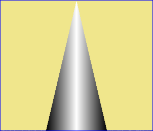
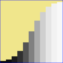
We can create cluts by enlarging a single pixel with various filters. The source image is five pixels wide, all black except for a central white pixel. Hence the average value is 0.2. The resulting cluts also average 0.2, except where they are truncated at the ends or by going negative.
%IMG7%magick ^
  xc: ^
  -bordercolor Black -border 2x0 ^
  cl_onepix.png

%IMG7%magick ^
  cl_onepix.png ^
  -filter triangle ^
  -resize "300x1^!" ^
  cl_filttri.png

call %PICTBAT%graph1d cl_filttri.png
|
|
|
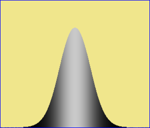
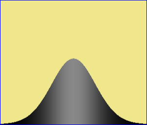
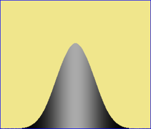
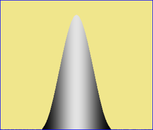
Gaussian with undefined (default) sigma.
%IMG7%magick ^
  cl_onepix.png ^
  -filter gaussian ^
  -resize "300x1^!" ^
  cl_filtgauss.png

call %PICTBAT%graph1d cl_filtgauss.png
Process modules: mkgauss describes a "-process" module in C for the same job.
|

|
|
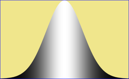
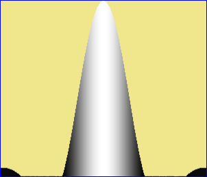
Gaussian with defined sigma.
%IMG7%magick ^
  cl_onepix.png ^
  -filter gaussian -define filter:sigma=0.5 ^
  -resize "300x1^!" ^
  cl_filtgauss0.png

call %PICTBAT%graph1d cl_filtgauss0.png
|
|
|
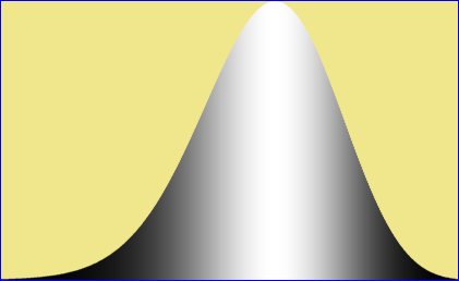
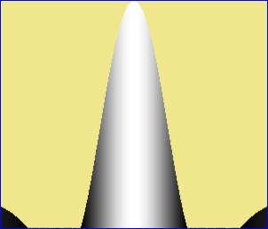
Gaussian with defined sigma.
%IMG7%magick ^
  cl_onepix.png ^
  -filter gaussian -define filter:sigma=0.75 ^
  -resize "300x1^!" ^
  cl_filtgauss0b.png

call %PICTBAT%graph1d cl_filtgauss0b.png
|
|
|
Gaussian with defined sigma.
%IMG7%magick ^
  cl_onepix.png ^
  -filter gaussian -define filter:sigma=1 ^
  -resize "300x1^!" ^
  cl_filtgauss1.png

call %PICTBAT%graph1d cl_filtgauss1.png
|

|
|
Gaussian with defined sigma.
%IMG7%magick ^
  cl_onepix.png ^
  -filter gaussian -define filter:sigma=2 ^
  -resize "300x1^!" ^
  cl_filtgauss2.png

call %PICTBAT%graph1d cl_filtgauss2.png
|

|
|
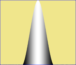
Asymmetrical Gaussian.
%IMG7%magick ^
  xc: ^
  -size 2x1 xc:Black +append +repage ^
  cl_onepixL.png

%IMG7%magick ^
  cl_onepixL.png ^
  -filter gaussian -define filter:sigma=1 ^
  -resize "300x1^!" ^
  cl_filtgauss_as.png

call %PICTBAT%graph1d cl_filtgauss_as.png
|

|
|
Half a Gaussian with defined sigma, normalized.
%IMG7%magick ^
  cl_onepix.png ^
  -filter gaussian -define filter:sigma=0.5 ^
  -resize "600x1^!" ^
  -crop 50x100%%+0+0 +repage ^
  -auto-level ^
  cl_filtgauss0h.png

call %PICTBAT%graph1d cl_filtgauss0h.png
|

|
|
Half a Gaussian with defined sigma, normalized.
%IMG7%magick ^
  cl_onepix.png ^
  -filter gaussian -define filter:sigma=0.75 ^
  -resize "600x1^!" ^
  -crop 50x100%%+0+0 +repage ^
  -auto-level ^
  cl_filtgauss0bh.png

call %PICTBAT%graph1d cl_filtgauss0bh.png
|

|
|
Half a Gaussian with defined sigma, normalized.
%IMG7%magick ^
  cl_onepix.png ^
  -filter gaussian -define filter:sigma=1 ^
  -resize "600x1^!" ^
  -crop 50x100%%+0+0 +repage ^
  -auto-level ^
  cl_filtgauss1h.png

call %PICTBAT%graph1d cl_filtgauss1h.png
|

|
|
Half a Gaussian with defined sigma, normalized.
%IMG7%magick ^
  cl_onepix.png ^
  -filter gaussian -define filter:sigma=2 ^
  -resize "600x1^!" ^
  -crop 50x100%%+0+0 +repage ^
  -auto-level ^
  cl_filtgauss2h.png

call %PICTBAT%graph1d cl_filtgauss2h.png
|

|
|
[Half] a Gaussian by blur.
%IMG7%magick ^
  -size 50x1 xc:White ^
  -size 200x1 xc:Black ^
  +append +repage ^
  -morphology Convolve Blur:0x30 ^
  -auto-level ^
  -flop ^
  cl_blur1.png

rem bash kernel2image.sh ^
rem   -g 1 blur:0x30 cl_blur1.png

%IMG7%magick ^
  cl_blur1.png ^
  -auto-level ^
  cl_blur1.png

call %PICTBAT%graph1d cl_blur1.png
|

|
|
[Half] a Gaussian by blur.
%IMG7%magick ^
  -size 50x1 xc:White ^
  -size 200x1 xc:Black ^
  +append +repage ^
  -morphology Convolve Blur:0x60 ^
  -auto-level ^
  -flop ^
  cl_blur2.png

rem bash kernel2image.sh ^
rem   -g 1 blur:0x60 cl_blur2.png

%IMG7%magick ^
  cl_blur2.png ^
  -auto-level ^
  cl_blur2.png

call %PICTBAT%graph1d cl_blur2.png
|

|
|
Gaussian by mkgauss.
%IM7DEV%magick ^
  xc: ^
  -process 'mkgauss w 419 sd 60 n' ^
  -delete 0 ^
  cl_mkg1.png

call %PICTBAT%graph1d cl_mkg1.png
|
|
|
Gaussian by mkgauss, skewed.
%IM7DEV%magick ^
  xc: ^
  -process 'mkgauss w 419 sd 60 k 10c n' ^
  -delete 0 ^
  cl_mkg2.png

call %PICTBAT%graph1d cl_mkg2.png
|
|
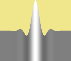
%IMG7%magick ^
  cl_onepix.png ^
  -filter catrom ^
  -resize "300x1^!" ^
  cl_filtcat.png

call %PICTBAT%graph1d cl_filtcat.png
|
|
%IMG7%magick ^
  cl_onepix.png ^
  -filter spline ^
  -resize "300x1^!" ^
  cl_filtspl.png

call %PICTBAT%graph1d cl_filtspl.png
|
|
%IMG7%magick ^
  cl_onepix.png ^
  -filter lanczos ^
  -resize "300x1^!" ^
  cl_filtlanc.png

call %PICTBAT%graph1d cl_filtlanc.png
|
|
%IMG7%magick ^
  cl_onepix.png ^
  -filter hamming ^
  -resize "300x1^!" ^
  cl_filtham.png

call %PICTBAT%graph1d cl_filtham.png
|
|
|
By using a wider source and mid-gray pixels each side of the white,
we see more of the Hamming curve.
%IMG7%magick ^
  -size 5x1 xc:gray50 ^
  -size 1x1 xc:white ^
  -size 5x1 xc:gray50 ^
  +append +repage ^
  cl_grayWhitePix.png

%IMG7%magick ^
  cl_grayWhitePix.png ^
  -filter hamming ^
  -resize "300x1^!" ^
  cl_filtham2.png

call %PICTBAT%graph1d cl_filtham2.png
|
|
%IMG7%magick ^
  cl_onepix.png ^
  -filter mitchell ^
  -resize "300x1^!" ^
  cl_filtmit.png

call %PICTBAT%graph1d cl_filtmit.png
|
|
Making staircases with filters:
%IMG7%magick ^
  xc:black xc:white ^
  +append +repage ^
  cl_bw.png

%IMG7%magick ^
  cl_bw.png ^
  -resize "11x1^!" ^
  -scale "220x1^!" ^
  cl_bw2.png

call %PICTBAT%graph1d cl_bw2.png
|
|
%IMG7%magick ^
  cl_bw.png ^
  -filter cubic ^
  -resize "11x1^!" ^
  -scale "220x1^!" ^
  cl_bw3.png

call %PICTBAT%graph1d cl_bw3.png
|
|
%IMG7%magick ^
  cl_bw.png ^
  -filter quadratic ^
  -resize "11x1^!" ^
  -scale "220x1^!" ^
  cl_bw4.png

call %PICTBAT%graph1d cl_bw4.png
|
|
%IMG7%magick ^
  cl_bw.png ^
  -filter gaussian ^
  -resize "11x1^!" ^
  -scale "220x1^!" ^
  cl_bw5.png

call %PICTBAT%graph1d cl_bw5.png
|
|
%IMG7%magick ^
  cl_bw.png ^
  -filter point ^
  -resize "11x1^!" ^
  -scale "220x1^!" ^
  cl_bw6.png

call %PICTBAT%graph1d cl_bw6.png
|

|
%IMG7%magick ^
  cl_bw.png ^
  -filter spline ^
  -resize "11x1^!" ^
  -scale "220x1^!" ^
  cl_bw7.png

call %PICTBAT%graph1d cl_bw7.png
|

|
%IMG7%magick ^
  cl_bw.png ^
  -filter triangle ^
  -resize "11x1^!" ^
  -scale "220x1^!" ^
  cl_bw8.png

call %PICTBAT%graph1d cl_bw8.png
|
|
Note that resizing with some filters creates results outside the range zero to 100%, aka "halos" or "ringing" or "overshoot":
%IM7DEV%magick ^
  cl_bw.png ^
  -filter Lanczos ^
  -resize "11x1^!" ^
  +depth ^
  txt:
# ImageMagick pixel enumeration: 11,1,0,4294967295,gray
0,0: (0)  #000000000000000000000000  gray(-25.31015%)
1,0: (0)  #000000000000000000000000  gray(-16.220701%)
2,0: (0)  #000000000000000000000000  gray(-3.6604706%)
3,0: (519838856)  #1EFC1C881EFC1C881EFC1C88  gray(12.103441%)
4,0: (1304122489)  #4DBB54794DBB54794DBB5479  gray(30.363968%)
5,0: (2147483648)  #800000008000000080000000  gray(50%)
6,0: (2990844806)  #B244AB86B244AB86B244AB86  gray(69.636035%)
7,0: (3775128440)  #E103E378E103E378E103E378  gray(87.896556%)
8,0: (4452183319)  #FFFFFFFFFFFFFFFFFFFFFFFF  gray(103.66048%)
9,0: (4991641077)  #FFFFFFFFFFFFFFFFFFFFFFFF  gray(116.2207%)
10,0: (5382029927)  #FFFFFFFFFFFFFFFFFFFFFFFF  gray(125.31015%)
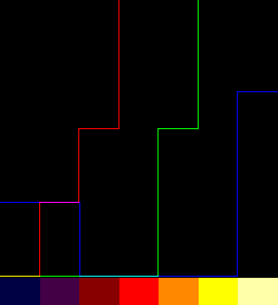
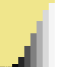
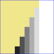
From a Nx1 clut, we can "-resize" to Mx1 to make another larger clut. The shape of the output will depend on the "-filter" setting. We demonstrate with a 4x1 input, and cycle through all the filters to make a montage:
%IMG7%magick ^
  xc:black xc:gray(80%%) xc:gray(20%%) xc:white ^
  +append +repage ^
  cl_rf_clut.miff

set FILES=

for /F "usebackq" %%I in (`%IMG7%magick -list filter`) do (

  %IMG7%magick ^
    cl_rf_clut.miff ^
    -virtual-pixel Edge ^
    -filter %%I ^
    -resize "256x1^!" ^
    cl_rf.png

  call %PICTBAT%graphLineCol cl_rf.png . . . cl_rf_%%I.miff

  %IMG7%magick ^
    cl_rf_%%I.miff ^
    -fill Yellow ^
    +antialias ^
    -pointsize 25 ^
    -gravity NorthWest ^
    -annotate 0 "%%I" ^
    cl_rf_%%I.miff

  set FILES=!FILES! cl_rf_%%I.miff
)

%IMG7%magick montage ^
  %FILES% ^
  -tile 3x ^
  -geometry 256x256+10+10 ^
  cl_rf_app.png
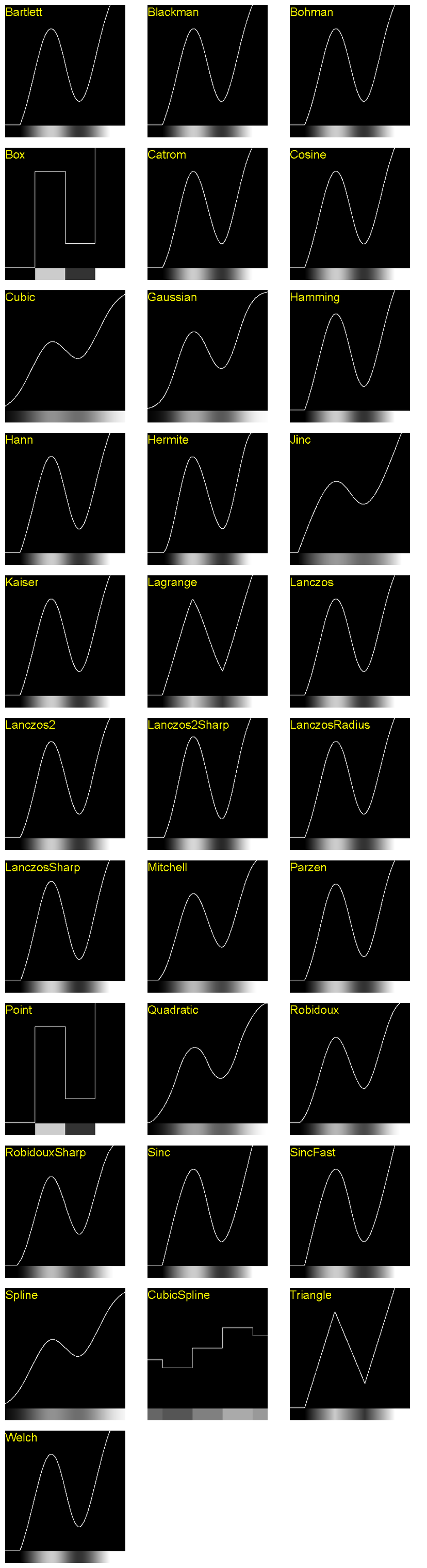
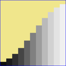
All curves pass through (0,0) and (1,1), but most curves are flat at the start and end. This is because values of the input pixels represent values at the centres of those pixels. If we want the curve to start at the last zero and end at the first 100%, for this example we need to crop 31 pixels from the left and right sides. Hence we can "-crop 194x1+31+0".
More generally: "-crop %[fx:w*(N-1)/N+2]x1+%[fx:w/N/2-1]+0" where N is the number of control points in the input clut, and w is the width of the output clut.
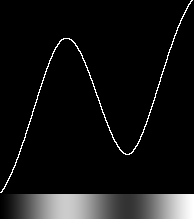
We want a curve that passes through control points, is second order continuous, and does not saturate. Which filters work well? Blackman, Bohman, Catrom, Lanczos and Parzen work well. Cosine, Hann, Hermite, Kaiser and Welch do not work well.
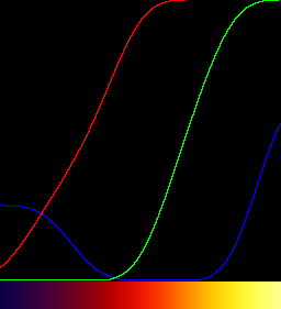
set FILT=Catrom
set N=4

%IMG7%magick ^
  xc:black xc:gray(80%%) xc:gray(20%%) xc:white ^
  +append +repage ^
  -virtual-pixel Edge ^
  -filter %FILT% ^
  -resize "256x1^!" ^
  -crop "%%[fx:w*(%N%-1)/%N%+2]x1+%%[fx:w/%N%/2-1]+0" +repage ^
  cl_rf_resize1.png

call %PICTBAT%graphLineCol ^
  cl_rf_resize1.png . . . cl_rf_resize1_g.png
|
|
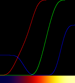
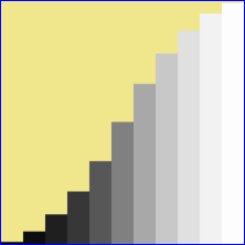
set N=3

%IMG7%magick ^
  xc:black xc:gray(75%%) xc:white ^
  +append +repage ^
  -virtual-pixel Edge ^
  -filter %FILT% ^
  -resize "256x1^!" ^
  -crop "%%[fx:w*(%N%-1)/%N%+2]x1+%%[fx:w/%N%/2-1]+0" +repage ^
  cl_rf_resize2.png

call %PICTBAT%graphLineCol ^
  cl_rf_resize2.png . . . cl_rf_resize2_g.png
|
|
set N=5

%IMG7%magick ^
  xc:Black xc:gray(10%%) xc:gray(60%%) ^
  xc:gray(90%%) xc:White ^
  +append +repage ^
  -virtual-pixel Edge ^
  -filter %FILT% ^
  -resize "256x1^!" ^
  -crop "%%[fx:w*(%N%-1)/%N%+2]x1+%%[fx:w/%N%/2-1]+0" +repage ^
  cl_rf_resize3.png

call %PICTBAT%graphLineCol ^
  cl_rf_resize3.png . . . cl_rf_resize3_g.png
|
|
See also
Interpolation settings below.
Some cluts are easily built in sections, appended together.
Caution: some time after IM v6.9.5-3 and before v6.9.9-40, "+append" was changed to set the page dimensions to the first input image, so graph1d.bat graphed only that portion. These commands now use "+repage".
%IMG7%magick ^
  -size 100x1 xc:gray(25%%) ^
  -size 100x1 gradient:gray(25%%)-gray(75%%) ^
  -size 100x1 gradient:gray(75%%)-gray(0%%) ^
  +append +repage ^
  cl_app1.png

call %PICTBAT%graph1d cl_app1.png
|
|
%IMG7%magick ^
  -size 100x1 gradient:black-white ^
  -size 100x1 gradient:white-black ^
  +append +repage ^
  cl_app2.png

call %PICTBAT%graph1d cl_app2.png
|

|
%IMG7%magick ^
  -size 50x1 gradient:black-white ^
  -size 50x1 gradient:white-black ^
  -size 50x1 gradient:black-white ^
  +append +repage ^
  cl_app3.png

call %PICTBAT%graph1d cl_app3.png
|
|
%IMG7%magick ^
  -size 50x1 gradient:black-white ^
  -size 50x1 gradient:white-black ^
  -size 50x1 gradient:black-white ^
  -size 50x1 gradient:white-black ^
  -size 50x1 gradient:black-white ^
  +append +repage ^
  cl_app4.png

call %PICTBAT%graph1d cl_app4.png
|

|
%IMG7%magick ^
  -size 50x1 gradient:black-white ^
  -size 100x1 xc:white ^
  -size 100x1 gradient:white-gray(50%%) ^
  +append +repage ^
  cl_app5.png

call %PICTBAT%graph1d cl_app5.png
|

|
%IMG7%magick ^
  -size 50x1 gradient:white-gray(10%%) ^
  -size 100x1 xc:gray(10%%) ^
  -size 100x1 gradient:gray(10%%)-gray(50%%) ^
  +append +repage ^
  cl_app6.png

call %PICTBAT%graph1d cl_app6.png
|

|
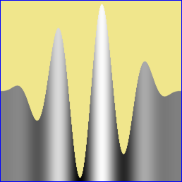
The script
mClutUpDn.bat makes a clut with a peak centred on a percentage of the width, with a given width of peak, and ramp up and down at each side of the peak.
In these examples, the width is set to 256, merely for illustration.
|
Default settings
call %PICTBAT%mClutUpDn ^
  256 . . . . . cl_mcud1.png
|

|
|
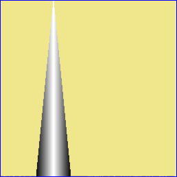
Centre peak at 30%, peak width 20%, ramp width 10%.
call %PICTBAT%mClutUpDn ^
  256 30 20 10 10 . cl_mcud2.png
|

|
|
Centre peak at 30%, peak width 0, ramp width 10%.
call %PICTBAT%mClutUpDn ^
  256 30 0 10 10 . cl_mcud2a.png
|
|
|
Centre peak at 30%, peak width 20%, ramp width 0.
call %PICTBAT%mClutUpDn ^
  256 30 20 0 0 . cl_mcud2b.png
|

|
|
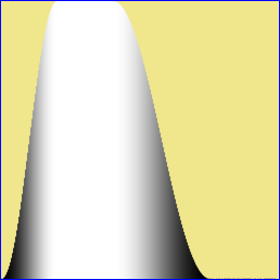
Centre peak at 30%, peak width 20%, ramp width 35%.
call %PICTBAT%mClutUpDn ^
  256 30 20 35 35 . cl_mcud3.png
|

|
|
As above, but with wrap.
call %PICTBAT%mClutUpDn ^
  256 30 20 35 35 1 cl_mcud4.png
|

|
|
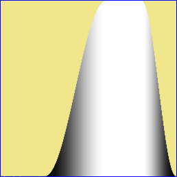
Centre peak at 70%, peak width 20%, ramp width 35%.
call %PICTBAT%mClutUpDn ^
  256 70 20 35 35 . cl_mcud5.png
|

|
|
As above, but with wrap.
call %PICTBAT%mClutUpDn ^
  256 70 20 35 35 1 cl_mcud6.png
|

|
|
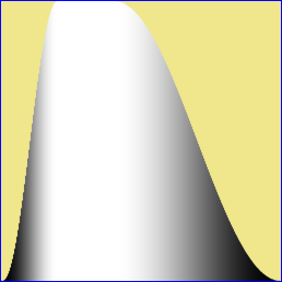
Centre peak at 30%, peak width 20%, ramp widths 20% and 60%.
call %PICTBAT%mClutUpDn ^
  256 30 20 20 60 . cl_mcud7.png
|

|
The wrap facility is useful when making masks for hues, when hue=0% is almost the same as hue=100%.
The environment variable mcudTRANS will transform the ramps, or perform any other transformation.
|
Default settings
set mcudTRANS=-sigmoidal-contrast 5x50%%
set mcudTRANS=-function sinusoid 0.5,-90,0.5,0.5

call %PICTBAT%mClutUpDn ^
  256 . . . . . cl_mcud1t.png
|

|
|
Centre peak at 30%, peak width 20%, ramp width 10%.
call %PICTBAT%mClutUpDn ^
  256 30 20 10 10 . cl_mcud2t.png
|

|
|
Centre peak at 30%, peak width 20%, ramp width 35%.
call %PICTBAT%mClutUpDn ^
  256 30 20 35 35 . cl_mcud3t.png
|
|
|
As above, but with wrap.
call %PICTBAT%mClutUpDn ^
  256 30 20 35 35 1 cl_mcud4t.png
|

|
|
Centre peak at 70%, peak width 20%, ramp width 35%.
call %PICTBAT%mClutUpDn ^
  256 70 20 35 35 . cl_mcud5t.png
|
|
|
As above, but with wrap.
call %PICTBAT%mClutUpDn ^
  256 70 20 35 35 1 cl_mcud6t.png
|

|
|
Centre peak at 30%, peak width 20%, ramp widths 20% and 60%.
call %PICTBAT%mClutUpDn ^
  256 30 20 20 60 . cl_mcud7t.png

set mcudTRANS=
|
|
See
Wikipedia: Smoothstep. Blah.
The script
smoothStep.bat, given a value N, calculates the coefficients for "-function Polynomial" where the polynomial order is 2N+1. The value of N determines how many derivatives are zero at the edges. Higher values of N also slightly increase the contrast in the centre, decreasing contrast at the ends.
The curve passes through (0,0), (0.5,0.5) and (1,1), with the inflection at (0.5,0.5).
call %PICTBAT%smoothStep 0

%IMG7%magick -size 1x100 gradient: -rotate 90 ^
  -function polynomial %sLIST% ^
  cl_smthst0.png
call %PICTBAT%graph1d cl_smthst0.png
|

|
call %PICTBAT%smoothStep 1

%IMG7%magick -size 1x100 gradient: -rotate 90 ^
  -function polynomial %sLIST% ^
  cl_smthst1.png
call %PICTBAT%graph1d cl_smthst1.png
|

|
call %PICTBAT%smoothStep 2

%IMG7%magick -size 1x100 gradient: -rotate 90 ^
  -function polynomial %sLIST% ^
  cl_smthst2.png
call %PICTBAT%graph1d cl_smthst2.png
|

|
call %PICTBAT%smoothStep 3

%IMG7%magick -size 1x100 gradient: -rotate 90 ^
  -function polynomial %sLIST% ^
  cl_smthst3.png
call %PICTBAT%graph1d cl_smthst3.png
|

|
call %PICTBAT%smoothStep 10

%IMG7%magick -size 1x100 gradient: -rotate 90 ^
  -function polynomial %sLIST% ^
  cl_smthst10.png
call %PICTBAT%graph1d cl_smthst10.png
|

|
The curve passes through (0.5,0.5). By raising it to a power, we can make it pass through (a,b) instead, but then derivatives at the ends may not be zero.
call %PICTBAT%smoothStep 2

set A=0.3
set B=0.7

%IMG7%magick -size 1x100 gradient: -rotate 90 ^
  -function polynomial %sLIST% ^
  -evaluate Pow %%[fx:log(%B%)/log(%A%)] ^
  cl_smthst_pow.png
call %PICTBAT%graph1d cl_smthst_pow.png
|

|
A colormap (aka "palette") is a structure used in some file formats. Each pixel in the file is a single scalar integer (typically 8-bit) value that is an index into the colormap. Each colormap entry defines a color. This reduces space requirements, both on disk and in memory, but limits the number of colours an image may contain. It can also reduce processing time: when the data is paletted in memory, some IM operations change every palette entry (typically 256) instead of every pixel (typically millions).
IM does not contain functions for users to edit colormaps.
The script
getColormap.bat reads the colormap of an image file, and writes an image with the same number of pixels, each being the colour of a colormap entry, in the same order.
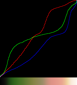
%IMG7%magick ^
  toes.png ^
  -colors 255 ^
  -type Palette ^
  cl_tpal.png

call %PICTBAT%getColormap ^
  cl_tpal.png cl_tpal_map.png

call %PICTBAT%graphLineCol cl_tpal_map.png
|
|
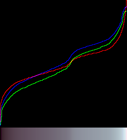
When creating colormaps, IM doesn't use any particular order; the order has no significance. We can sort the map image by intensity using
Process modules: sort pixels:
%IM7DEV%magick ^
  cl_tpal_map.png ^
  -process sortpixels ^
  cl_tpal_srt.png

call %PICTBAT%graphLineCol cl_tpal_srt.png
|
|
Cumulating (integrating) a clut makes another clut. This uses
Process modules: cumulate histogram.
%IM7DEV%magick ^
  cl_app1.png ^
  -process 'cumulhisto norm' ^
  cl_app1_ch.png

call %PICTBAT%graph1d cl_app1_ch.png
|

|
%IM7DEV%magick ^
  cl_app2.png ^
  -process 'cumulhisto norm' ^
  cl_app2_ch.png

call %PICTBAT%graph1d cl_app2_ch.png
|

|
%IM7DEV%magick ^
  cl_app3.png ^
  -process 'cumulhisto norm' ^
  cl_app3_ch.png

call %PICTBAT%graph1d cl_app3_ch.png
|

|
%IM7DEV%magick ^
  cl_app4.png ^
  -process 'cumulhisto norm' ^
  cl_app4_ch.png

call %PICTBAT%graph1d cl_app4_ch.png
|

|
%IM7DEV%magick ^
  cl_app5.png ^
  -process 'cumulhisto norm' ^
  cl_app5_ch.png

call %PICTBAT%graph1d cl_app5_ch.png
|

|
%IM7DEV%magick ^
  cl_app6.png ^
  -process 'cumulhisto norm' ^
  cl_app6_ch.png

call %PICTBAT%graph1d cl_app6_ch.png
|

|
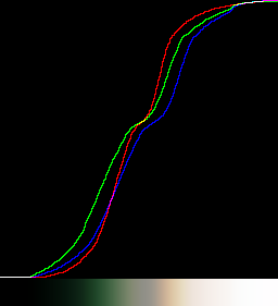
Where a clut starts and ends at y=0, adding a gradient will make a clut that starts at y=0 and ends at y=1.
In these examples, the base clut rises to y=100% at x=20%, then from x=40% y falls to zero. By adding a gradient to a fraction of that base clut, the result rises above the y=x diagonal, then falls down to it. The fraction is 0.3, so the amount above y=x is 30%.
We have a linear rise and fall, or sigmoidal rise and fall.
Beware that a steep fall in the base clut may create a result that does not monotonically increase.
%IMG7%magick ^
  cl_mcud7.png ^
  ( +clone ^
    -sparse-color bilinear "0,0,Black %%[fx:w-1],0,White" ^
  ) ^
  -compose Mathematics ^
    -define compose:args=0,1,0.3,0 -composite ^
  cl_mcud7_add.png

call %PICTBAT%graph1d cl_mcud7_add.png
|

|
%IMG7%magick ^
  cl_mcud7t.png ^
  ( +clone ^
    -sparse-color bilinear "0,0,Black %%[fx:w-1],0,White" ^
  ) ^
  -compose Mathematics ^
    -define compose:args=0,1,0.3,0 -composite ^
  cl_mcud7t_add.png

call %PICTBAT%graph1d cl_mcud7t_add.png
|

|
We can subtract from the gradient:
%IMG7%magick ^
  cl_mcud7.png ^
  ( +clone ^
    -sparse-color bilinear "0,0,Black %%[fx:w-1],0,White" ^
  ) ^
  -compose Mathematics ^
    -define compose:args=0,1,-0.1,0 -composite ^
  cl_mcud7_sub.png

call %PICTBAT%graph1d cl_mcud7_sub.png
|

|
%IMG7%magick ^
  cl_mcud7t.png ^
  ( +clone ^
    -sparse-color bilinear "0,0,Black %%[fx:w-1],0,White" ^
  ) ^
  -compose Mathematics ^
    -define compose:args=0,1,-0.1,0 -composite ^
  cl_mcud7t_sub.png

call %PICTBAT%graph1d cl_mcud7t_sub.png
|

|
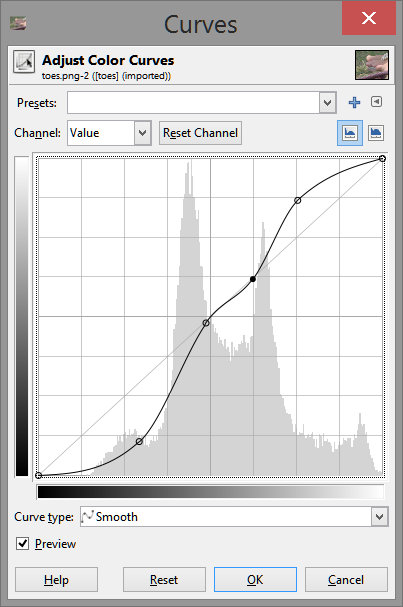
We can create cluts (or hald-cluts) in Gimp. For example, we might want a complex tone curve that processes a photograph in a particular way. If we apply that same tone curve to a gradient, we have created a clut.
|
In Gimp, open the photograph.
Menu "Color, Curves".
The curves panel shows a histogram and the curve,
which initially is a straight diagonal line.
|

|
|
Adjust the curve as desired.
|
|
Save the curve as a preset, with any name you want.
At the command prompt, create a gradient.
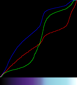
%IMG7%magick -size 1x256 gradient: -rotate 90 cl_grad.png
In Gimp, open this gradient file cl_grad.png. If you want to see it, zoom to 800% or whatever. Menu "Color, Curves". Open the saved preset curve. The lastest saved is at the bottom of the list. "OK" it. This applies the curve to the gradient. Export the result as a PNG, eg named cl_gimp_clut.png. (In the "Export image as..." window, the box "Save gamma" should generally be ticked.) This result is a 256x1 clut, so we can visualise it in the usual way.
call %PICTBAT%graph1d cl_gimp_clut.png
|

|
The curve shown is the same as the one we created in Gimp.
Aside: I first discovered the joys of digital images through Gimp, and especially the Curves facility. Playing with Curves is a great way of learning about tonal shifts, and discovering the effects of IM operations "-gamma", "level", "-sigmoidal-contrast", etc. The opposite is also true: showing a clut as a graph is a useful way of identifying the effect of a clut.
Further side: The process described above of creating a gradient, applying a saved curve in Gimp, and saving it as a clut is somewhat tedious and error-prone. Gimp saves curves in a simple text format, so I wrote gimpCurve.exe to read the file and create a clut. I don't curently publish this program. I suppose the task would be quite simple as a Unix script.
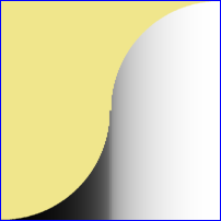
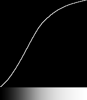
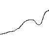
Given a black line on a white background that represents a gradient, we can convert it to a clut. We write and show intermediate results (cl_*_tmp.png) purely for illustration.
|
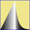
An example source file, clutLine.png.
|
|
|
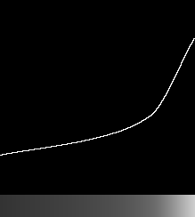
Turn black the white pixels above the black pixels and resize to one line.
"-scale" (instead of "-resize") gives the arithmetically average result.
We write and show the intermediate result (cl_clutLine_tmp.png) purely for illustration.
%IMG7%magick clutLine.png ^
  -morphology Distance "1x2+0+1:0,1" ^
  -write cl_clutLine_tmp.png ^
  -scale "100x1^!" ^
  +depth ^
  cl_clutLine.png

call %PICTBAT%graph1d cl_clutLine.png
|


|
|
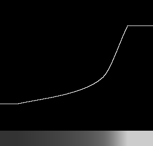
How close is the result?
The input and output have the same dimensions, so can be directly compared.
%IMG7%magick clutLine.png ^
  cl_clutLine_g1d.png ^
  ( clutLine.png -transparent White ) ^
  -gravity Center ^
  -composite ^
  cl_clutLineComp.png
|
|
This clut can be used as a vertical-only displacement map that would make the line horizontal. See
Displacement maps.
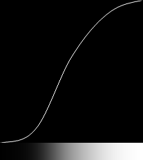
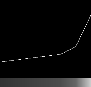
If the line has a thickness, we can find the top, bottom or middle. We write and show intermediate results (*_tmp.png) purely for illustration.
|
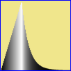
An example source file, clutLineThk.png.
|

|
|
Find the top of the line.
Turn black all the white pixels below the line, resize and negate.
Note that the resulting black includes all of the line.
%IMG7%magick clutLineThk.png ^
  -morphology Distance "1x2+0+0:0,1" ^
  -write cl_clutLineThkT_tmp.png ^
  -scale "100x1^!" ^
  -negate ^
  +depth ^
  cl_clutLineThkT.png

call %PICTBAT%graph1d cl_clutLineThkT.png
|


|
|
Find the bottom of the line.
Turn black the white pixels above the black pixels and resize to one line.
%IMG7%magick clutLineThk.png ^
  -morphology Distance "1x2+0+1:0,1" ^
  -write cl_clutLineThkB_tmp.png ^
  -scale "100x1^!" ^
  +depth ^
  cl_clutLineThkB.png

call %PICTBAT%graph1d cl_clutLineThkB.png
|


|
|
Find the middle of the line. (strLine6)
We find the top of the black blob and make all pixels beneath it black.
Then paint a mid-gray version of the blob over it.
Thus the resize to a single line will use the height plus half the height of the thick line.
%IMG7%magick ^
clutLineThk.png ^
( -clone 0 ^
-virtual-pixel white ^
-morphology EdgeOut rectangle:1x2 ^
-negate ^
-morphology Distance "1x2+0+0:0,1" ^
-threshold 50%% ^
) ^
( -clone 0 -function Polynomial -1,0.5 ) ^
-delete 0 ^
-compose Lighten -composite ^
-write cl_clutLineThkM_tmp.png ^
-scale "100x1^!" ^
-negate ^
cl_clutLineThkM.png
call %PICTBAT%graph1d cl_clutLineThkM.png
|


|
|
Alternate Find the middle of the line.
Turn black all the white pixels below the line.
Then paint a mid-gray version of the blob over it.
Thus the resize to a single line will use the height plus half the height of the thick line.
%IMG7%magick ^
clutLineThk.png ^
( -clone 0 ^
-morphology Distance "1x2+0+0:0,1" ^
) ^
( -clone 0 -function Polynomial -1,0.5 ) ^
-delete 0 ^
-compose Lighten -composite ^
-write cl_clutLineThkM2_tmp.png ^
-scale "100x1^!" ^
-negate ^
cl_clutLineThkM2.png
call %PICTBAT%graph1d cl_clutLineThkM2.png
|


|
|
Make a blink-comparator using animated gif.
%IMG7%magick ^
-delay 50 ^
clutLineThk.png ^
cl_clutLineThkT_tmp.png ^
clutLineThk.png ^
cl_clutLineThkM_tmp.png ^
clutLineThk.png ^
cl_clutLineThkB_tmp.png ^
cl_clutLineThkComp.gif
|

|
As mentioned above, we can use cluts as displacement maps. The cluts we have generated are light where the line is above the centre. Hence we need to invert the displacement to move the line to the centre. We do this with a negative argument which is roughly half the height because we want black (or white) in the clut to move a pixel from the bottom (or top) of the source image to the image center.
The image is 100 pixels high. The centre of the image is at 49.5.
The line is at least one pixel high. Without an "-evaluate" offset, alignment with the three methods would place the top of the top-most pixel at the same location as the bottom of the bottom-most pixel, at the same location as the middle of the middle-most pixel. If we want to line up pixels instead of boundaries, we need to move the top-aligned image down by half a pixel and the bottom-aligned image up half a pixel. We do this by subtracting or adding an offset to the clut. As the height is 100 pixels, half a pixel is 0.5% of quantum.
|
Align the top of the thick line.
%IMG7%magick ^
clutLineThk.png ^
( cl_clutLineThkT.png -evaluate subtract 0.5%% -scale "100x100^!" ) ^
-compose Displace -set option:compose:args 0x-50 -composite ^
-compose Over -bordercolor khaki -border 1 ^
cl_clutLineThk_dispT.png
|

|
|
Align the bottom of the thick line.
%IMG7%magick ^
clutLineThk.png ^
( cl_clutLineThkB.png -evaluate add 0.5%% -scale "100x100^!" ) ^
-compose Displace -set option:compose:args 0x-50 -composite ^
-compose Over -bordercolor khaki -border 1 ^
cl_clutLineThk_dispB.png
|

|
|
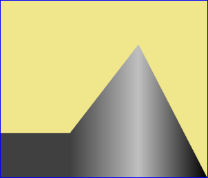
Align the middle of the thick line.
The 50% crop is for later use.
%IMG7%magick ^
clutLineThk.png ^
+depth ^
( cl_clutLineThkM.png -scale "100x100^!" ) ^
-compose Displace -set option:compose:args 0x-50 -composite ^
( +clone ^
-gravity North -crop 100%%x50%%+0+0 ^
+repage ^
-write cl_halfThk.png +delete ^
) ^
-compose Over -bordercolor khaki -border 1 ^
cl_clutLineThk_dispM.png
|

|
|
Blink comparator.
%IMG7%magick ^
-delay 50 ^
cl_clutLineThk_dispT.png ^
cl_clutLineThk_dispB.png ^
cl_clutLineThk_dispM.png ^
cl_clutLineThk_disp_comp.gif
|

|
When a source image is displaced in this way, some of the image will be displaced out of the resulting image. The source may be given an "-extent" first.
This technique could be used to make text flow parallel with the edge of a containing shape. See
SVG text: Rotating text in areas.
A different displacement is also of interest. Take the top half of the middle-aligned thick line, created above.
|
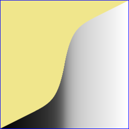
Half the middle-aligned thick line.
cl_halfThk.png
|

|
We can spread this vertically, by different amounts along the horizontal line, to fit the rectangle.
Values in the top row of the displacement map (whether absolute or relative), will be the average lightness of the column. Values in the bottom row will be 1.0 for the absolute map, or 0.5 for the relative map. Values in intermediate rows will vary linearly. So we can create a relative map quite easily.
This relative map has to be multipled by the height (not half the height) to obtain the full displacement.
|
Make the relative map.
FOR /F "usebackq" %%L ^
IN (`%IMG7%magick identify ^
-format "htWW=%%w\nhtHH=%%h\nhtHHm1=%%[fx:h-1]\nhtHHp1=%%[fx:h+1]" ^
cl_halfThk.png`) ^
DO set %%L
%IMG7%magick ^
cl_halfThk.png ^
-gravity South -chop 0x1 ^
-scale "%htWW%x1^!" -scale "%htWW%x%htHH%^!" ^
-size %htWW%x%htHH% gradient: ^
-compose Mathematics ^
-define compose:args=0.5,0,0,0.5 ^
-composite ^
+depth ^
cl_halfThkMap.png
|

|
|
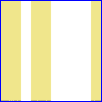
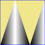
Apply the relative map.
%IMG7%magick ^
cl_halfThk.png ^
cl_halfThkMap.png ^
-background Red -virtual-pixel background ^
-compose Displace ^
-set option:compose:args 0x%htHHm1% ^
-composite ^
cl_halfThkMapped.png
Grey bands occur where the bottom line
of cl_halfThk.png is grey.
|

|
For the inverse displacement, converting a black rectangle into the black shape cl_halfThk.png, the absolute map should be anything negative (ie darker than mid-grey) where we want white (so it fetches a virtual pixel), and the bottom line is 1.0, white, so pixels come from the bottom line of the black rectangle. Map pixels at the top of the black shape should be 0.0, black, so pixels come from the top line of the black rectangle.
Taking relative values as -1.0 .. 0.0 .. +1.0: For the inverse relative map, pixels at the bottom will be 0. For the forwards displacement, pixels are displaced fom the top of the blob to the top of the image. The inverse displacement needs to do the opposite, so pixels for the inverse displacement at the top of the blob will be -(pixels at top of forwards displacement). So pixels at top of inverse map will be -f*(pixels at top of forwards displacement) where f is (height / number of black pixels in column). [[the average lightness of negated cl_halfThk.png.]]
[[and anything positive (ie lighter than mid-grey) where we want black. An obvious choice for the absolute map is cl_halfThk.png negated.]]
|
From the relative map, make the absolute map, and rotate it so the displacements are horizontal.
%IMG7%magick ^
cl_halfThkMap.png ^
-size %htWW%x%htHH% gradient:black-white ^
-compose Mathematics ^
-define compose:args=0,1,1,-0.5 ^
-composite ^
-rotate -90 ^
+repage ^
-function polynomial 2,-1 ^
+depth ^
cl_halfThkAbs.png
|

|
|
Invert the absolute map.
call %PICTBAT%inv2dAbsDisp cl_halfThkAbs.png cl_halfThkAbs_iad.png
|

|
|
Rotate the absolute map back, and convert it to relative.
%IMG7%magick ^
cl_halfThkAbs_iad.png ^
-rotate 90 ^
-size %htWW%x%htHH% ^
gradient:black-white ^
-compose Mathematics ^
-define compose:args=0,-0.5,1,0.5 ^
-composite ^
cl_halfThkAbs_iad_rel.png
|

|
|
Apply the relative map to a black rectangle.
%IMG7%magick ^
-size %htWW%x%htHH% xc:Black ^
cl_halfThkAbs_iad_rel.png ^
-background Red -virtual-pixel background ^
-compose Displace ^
-set option:compose:args 0x50 ^
-composite ^
cl_halfThkAbs_iad_rel_b.png
|

|
A curve that is flat from (0,0) to (BB,0), then a power curve that passes through (XX,YY), then is flat from (WW,1) to (1,1), where 0.0 <= BB < XX < WW <= 1.0 and 0.0 < YY < 1.0. For example:
set BB=0.05
set WW=0.85
set XX=0.5
set YY=0.7
%IMG7%magick -size 1x256 gradient: -rotate 90 ^
-evaluate Subtract %%[fx:%BB%*QuantumRange] ^
-evaluate Divide %%[fx:%WW%-%BB%] ^
-evaluate Pow %%[fx:log(%YY%)/log((%XX%-%BB%)/(%WW%-%BB%))] ^
cl_bgw_1.png
call %PICTBAT%graph1d cl_bgw_1.png
|

|
The Subtract and Divide could be combined into a single -function Polynomial.
The script
mkClut2slp.bat makes a clut from two slopes: from (0,0) to (x0,y0), and from (x0,y0) to (1,1). Optionally it also smooths the values with a transition curve at (x0,y0), so it won't actually pass through (x0,y0).
|
With no transition curve.
call %PICTBAT%mkClut2slp cl_2sp_1.png 512 "0.6,0.3"
if ERRORLEVEL 1 exit /B 1
call %PICTBAT%graph1d cl_2sp_1.png
|

|
|
With a transition curve.
call %PICTBAT%mkClut2slp cl_2sp_2.png 512 "0.6,0.3" 0.05
if ERRORLEVEL 1 exit /B 1
call %PICTBAT%graph1d cl_2sp_2.png
|

|
If we have a few values and want a spline curve to pass through them, my cBezCurve.exe can do the job. But that program isn't published.
Instead, we can use gnuplot, which is widely available for Unix and Windows. In gnuplot terms, the x-axis is the IM x-coordinate of the clut, integers starting at zero; the y-axis is the floating-point values at those x-coordinates as a percentage of QuantumRange, so a typical range for y is 0.0 to 100.0. gnuplot will take a list of sparse points, do the calculations for piece-wise curves between each pair of sparse points, and sample the entire curve from the first point to the last.
First, we make a sparse clut image. It is transparent except for the sparse points.
%IMG7%magick ^
-size 300x1 xc:None ^
-fill graya(20%%,1) -draw "point 0,0" ^
-fill graya(30%%,1) -draw "point 200,0" ^
-fill graya(40%%,1) -draw "point 250,0" ^
-fill graya(80%%,1) -draw "point 299,0" ^
-define quantum:format=floating-point -depth 32 ^
cl_spsecl.miff
The script
clut2txt.bat reads a sparse clut image and writes a text file suitable for gnuplot to read.
call %PICTBAT%clut2txt cl_spsecl.miff cl_spsecl_in.txt
The created text file cl_spsecl_in.txt is:
0 20
200 30
250 40
299 80
The script
smoothSparse.bat passes that text file to gnuplot, to create another text file that fills in the missing values.
call %PICTBAT%smoothSparse cl_spsecl_in.txt cl_spsecl_out.txt
The first and last few lines of the output text file cl_spsecl_out.txt are:
# Curve 0 of 1, 304 points
# Curve title: "'cl_spsecl_in.txt' using 1:2"
# x y type
0 20 i
0 20 i
1 20.0498 i
:
:
297 78.3286 i
298 79.1738 i
298.5 79.5893 i
299 80 i
The script
txt2clut.bat reads the text file and writes the clut image. gnuplot throws in extra lines: the first data point is duplicated, and it creates x-values of (integer minus 0.5) at the end of each segment. These extra lines would cause IM to stop before the end of the TXT: file, so txt2clut.bat strips them.
call %PICTBAT%txt2clut cl_spsecl_out.txt cl_spsecl_out.png
We graph the result:
call %PICTBAT%graphLineCol cl_spsecl_out.png
|

|
In the next example, the first sparse point isn't at x=0. The output will represent the sparse clut only between the first and last sparse point, inclusive. In this case, the width of the result will be (250-32+1)=219 pixels.
%IMG7%magick ^
-size 300x1 xc:None ^
-fill graya(20%%,1) -draw "point 32,0" ^
-fill graya(30%%,1) -draw "point 150,0" ^
-fill graya(40%%,1) -draw "point 200,0" ^
-fill graya(80%%,1) -draw "point 250,0" ^
-define quantum:format=floating-point -depth 32 ^
cl_spsecl2.miff
if ERRORLEVEL 1 exit /B 1
call %PICTBAT%clut2txt cl_spsecl2.miff cl_spsecl2_in.txt
if ERRORLEVEL 1 exit /B 1
call %PICTBAT%smoothSparse cl_spsecl2_in.txt cl_spsecl2_out.txt
if ERRORLEVEL 1 exit /B 1
call %PICTBAT%txt2clut cl_spsecl2_out.txt cl_spsecl2_out.png
rem if ERRORLEVEL 1 exit /B 1
call %PICTBAT%graphLineCol cl_spsecl2_out.png
|
|
We can tell the script to extend the first value back to zero, and the last value to whatever width we want.
call %PICTBAT%txt2clut cl_spsecl2_out.txt cl_spsecl2_out2.png 300 extend
rem if ERRORLEVEL 1 exit /B 1
call %PICTBAT%graphLineCol cl_spsecl2_out2.png
|
|
For a sample input, we use cl_spsecl.miff made in the previous section. This is a 300x1 image with four opaque pixels; the rest are transparent.
Convergence is very slow. For an accurate result, we need a small error margin (1e-7) and a large limit to the number of iterations (100000).
%IMG7%magick ^
cl_spsecl.miff ^
( -clone 0 -alpha off -fill Black -colorize 100 ) ^
( -clone 0 -alpha extract -negate ) ^
-compose seamless-blend ^
-define compose:args=100000x1e-7+1000 ^
-composite ^
-alpha off ^
cl_seamless.png
if ERRORLEVEL 1 exit /B 1
call %PICTBAT%graphLineCol cl_seamless.png
|
|
A Hermite curve is defined by the values at each end (v0 and v1) and the gradients at each end (m0 and m1). It is commonly defined using a parameter t that varies from 0.0 to 1.0 between the start and end of the curve. The value of the curve v(t) at a value of t is:
v(t) = h00(t)*v0 + h10(t)*m0 + h01(t)*v1 + h11(t)*m1
... where the Hermite basis functions are:
h00(t) = 2t3-3t2+1
h10(t) = t3-2t2+t
h01(t) = -2t3+3t2
h11(t) = t3-t2
... where t varies linearly from 0.0 to 1.0 along the curve, v0 and v1 are the values and m0 and m1 are the gradients at t==0 and t==1.
The script
mkHermiteClutImg.bat calculates the image that represents each of t (a linear gradient), t2, t3, h00(t), h10(t), h01(t) and h11(t), and from these it calculates v(t) by calling the general-purpose
interpClutHermite.bat.
A more direct (and faster) implementation comes from expanding the expression for v(t):
v(t) = (2t3-3t2+1)*v0 +
(t3-2t2+t)*m0 +
(-2t3+3t2)*v1 +
(t3-t2)*m1
= v0*2t3-v0*3t2+v0 +
m0*t3-m0*2t2+m0*t +
v1*-2t3+v1*3t2 +
m1*t3-m1*t2
= t3*(2v0 +m0 -2v1 +m1) +
t2*(-3v0 -2m0 +3v1 - m1) +
t*(m0) +
(v0)
So we have the four coefficients of a cubic polynomial, and can simply use IM's "-function polynomial", in the script
mkHermiteClut.bat.
In the scripts, values v0, v1 and v(t) are expressed as a percentage of QuantumRange.
Gradient is more awkward, because the numerator and denominator of the slope have different units. The scripts provide for three definitions:
- In the basic definition of Hermite curves, the gradient is the rise in values (which we express as a percentage of QuantumRange) we would get if the tangent spanned the entire curve (ie from t=0 to t=1). For example, when graphed, a gradient of 20% would be parallel to a line that starts at the origin and ends at 20% of QuantumRange at the end of the image. This is GRAD_TYPE perimage.
- An alternative is: the rise in values (again, as a percentage of QuantumRange) from one percentage of the image to the next percentage (eg from t=0 to t=0.01). For example, a gradient of 0.2% would give the same result as above. This is GRAD_TYPE perpercent.
- Yet another alternative: the rise in values (again, as a percentage of QuantumRange) from one pixel to the next. For example, with 100 pixels a gradient of 0.2%, or with 500 pixels a gradient of 0.04%, would give the same result as above. This is GRAD_TYPE perpixel, the default method.
The perimage and perpercent gradient types are simple to understand when we are creating single Hermite curves, but are not so obvious when we are joining piecewise single curves into a longer spline (see below), as they refer to each piece individually.
When values increase from left to right, the gradient is positive.
For example, using the different gradient types and adjusting the parameters to get the same result:
|
Default gradient type
call %PICTBAT%mkHermiteClut ^
cl_herm_h2.miff ^
20 80 500 0.1 -0.3
call %PICTBAT%graphLineCol cl_herm_h2.miff
|

|
|
Gradient type perimage
call %PICTBAT%mkHermiteClut ^
cl_herm_h3.miff ^
20 80 500 50 -150 ^
perimage
call %PICTBAT%graphLineCol cl_herm_h3.miff
|

|
|
Gradient type perpercent
call %PICTBAT%mkHermiteClut ^
cl_herm_h4.miff ^
20 80 500 0.5 -1.5 ^
perpercent
call %PICTBAT%graphLineCol cl_herm_h4.miff
|
|
|
Gradient type perpixel
call %PICTBAT%mkHermiteClut ^
cl_herm_h5.miff ^
20 80 500 0.1 -0.3 ^
perpixel
call %PICTBAT%graphLineCol cl_herm_h5.miff
|

|
From a series of Hermite curves, we can make a spline. The curves will overlap by one pixel, to ensure the last pixel of one curve and the first pixel of the next have the same value and gradient. The script
mkHermiteSpline.bat reads a text data file and makes a grayscale Nx1 clut image that is the spline specified by the data file. The script removes one of each pair of overlapping pixels.
The data file should contain one line per point that has a required value and gradient. Gradients must be of the perpixel type. Each line of the data file represents the start of one Hermite segment, or the end of another, or both.
Each line should have two or three numbers:
- x-coordinate, an integer;
- value at that coordinate, a percentage of QuantumRange;
- optionally, the gradient at that coordinate, of type perpixel.
Where the gradient is not specified, the script will use zero for the first and last points, and for all other points will use the slope between the adjacent points.
The data file could be made in a text editor or programatically.
(
echo 150, 20
echo 400, 30
echo 599, 80
) >cl_herm_d1.dat
The clut will have 600x1 pixels. The value at x=0 has not been specified, so the script will act as if a line was inserted at the start "0,0,0", so at x=0, the value will be gray(0) and the gradient there will be zero. So the value at four points have been specified, and there will be three segments.
At x=0, the value will be gray(0), black. At x=150, the value will be gray(20%). At x=400, the value will be gray(30%). At x=599, the value will be gray(80%).
call %PICTBAT%mkHermiteSpline ^
cl_herm_d1.dat cl_herm_d1.miff
call %PICTBAT%graphLineCol cl_herm_d1.miff
|
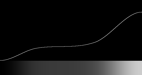
|
We check that the result has 600 pixels, and 600 unique values (because this spline should always increase).
%IMG7%magick ^
cl_herm_d1.miff ^
+write info: ^
-unique-colors ^
info:
cl_herm_d1.miff MIFF 600x1 600x1+0+0 32-bit TrueColor sRGB 7692B 0.000u 0:00.000
cl_herm_d1.miff MIFF 600x1 600x1+0+0 32-bit sRGB 7692B 0.000u 0:00.000
We repeat, but with explicit gradients:
(
echo 0, 0, 0.1
echo 150, 20, -0.1
echo 400, 30, 0.2
echo 599, 80, -0.2
) >cl_herm_d2.dat
call %PICTBAT%mkHermiteSpline ^
cl_herm_d2.dat cl_herm_d2.miff
call %PICTBAT%graphLineCol cl_herm_d2.miff
|
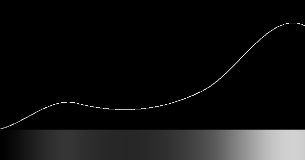
|
For some purposes, we might want to find the minimum and maximum gradients of the curve. We might also want to limit these values, for example to ensure the curve never has a negative gradient, or always has a gradient greater than zero. This might create second-order discontinuity (ie sudden change of slope). This is not explored further here.
Other examples:
(
echo 0, 0
echo 150, 100
echo 599, 0
) >cl_herm_d3.dat
call %PICTBAT%mkHermiteSpline ^
cl_herm_d3.dat cl_herm_d3.miff
call %PICTBAT%graphLineCol cl_herm_d3.miff
|
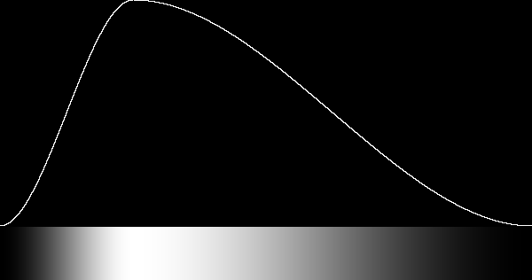
|
(
echo 0, 0
echo 150, 80
echo 300, 80
echo 599, 0
) >cl_herm_d4.dat
call %PICTBAT%mkHermiteSpline ^
cl_herm_d4.dat cl_herm_d4.miff
call %PICTBAT%graphLineCol cl_herm_d4.miff
|
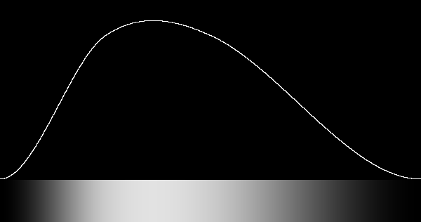
|
(
echo 0, 0
echo 599, 100
) >cl_herm_d5.dat
call %PICTBAT%mkHermiteSpline ^
cl_herm_d5.dat cl_herm_d5.miff
call %PICTBAT%graphLineCol cl_herm_d5.miff
|
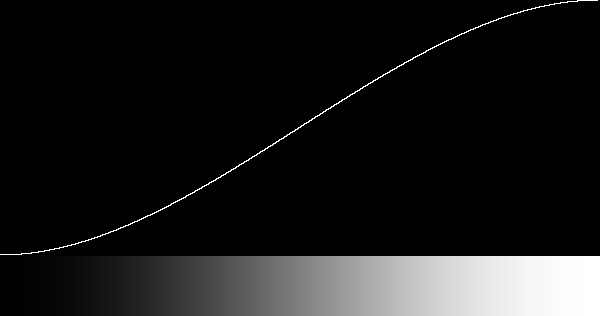
|
The geometric mean of an orthogonal pair of Hermite splines can be used for 2D gradients. For example:
%IMG7%magick ^
cl_herm_d3.miff ^
( +clone -rotate 90 ) ^
-scale "600x600^!" ^
-compose Multiply -composite ^
-evaluate Pow 0.5 ^
cl_herm_2d.png
|

|
A clut may have different values in the three channels. This could, for example, be used to apply a false colour to a monochrome image.
We can use any of the above techniques on individual channels, for example:
%IMG7%magick -size 1x256 gradient: -rotate 90 ^
-channel R -evaluate sin 1 ^
-channel G -evaluate cos 1 ^
+channel ^
cl_chan1.png
call %PICTBAT%graphLineCol cl_chan1.png
|
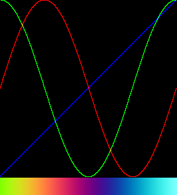
|
See also the closely-related
Colour wheels.
In HSL and related colorspaces, vary the first channel from zero to 100% as the x-dimension. Set the second and third channels to 100%.
set WW=256
for %%H in (HSL,HSB,HSI,HSV,HCL,HCLp,HWB) do (%IMG7%magick ^
-size 1x%WW% gradient: -rotate 90 ^
-size %WW%x1 xc:#fff ^
-size %WW%x1 xc:#fff ^
-combine -set colorspace %%H ^
-colorspace sRGB ^
cl_rb_%%H.png
call %PICTBAT%graphLineCol cl_rb_%%H.png
%IMG7%magick ^
cl_rb_%%H_glc.png ^
-gravity Center label:"%%H x,100%%,100%%" ^
-append +repage ^
cl_rb_%%H_glc.png
)


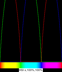
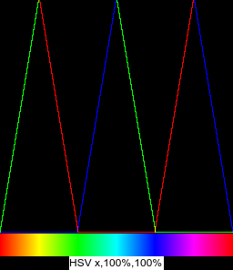
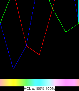

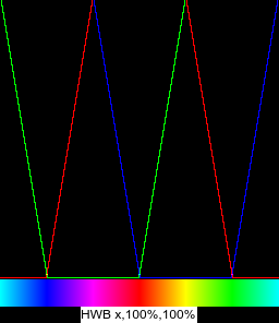
As above but set the second channel to 50%.
for %%H in (HSL,HSB,HSI,HSV,HCL,HCLp,HWB) do (%IMG7%magick ^
-size 1x%WW% gradient: -rotate 90 ^
-size %WW%x1 xc:#fff ^
-size %WW%x1 xc:gray^(50%%^) ^
-combine -set colorspace %%H ^
-colorspace sRGB ^
cl_rb_%%H_2.png
call %PICTBAT%graphLineCol cl_rb_%%H_2.png
%IMG7%magick ^
cl_rb_%%H_2_glc.png ^
-gravity Center label:"%%H x,100%%,50%%" ^
-append +repage ^
cl_rb_%%H_2_glc.png
)
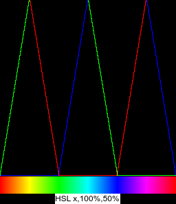
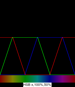
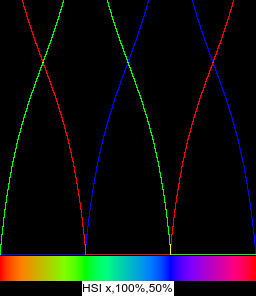

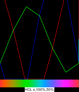
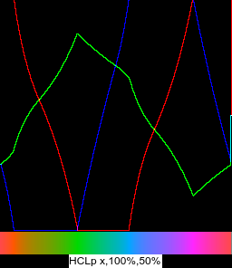
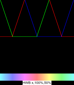
Or we can use a technique that lists explicit colours, such as one of those below.
%IMG7%magick ^
-size 1x256 gradient: -rotate 90 ^
( -size 1x1 ^
xc:#f00 xc:#ff0 xc:#0f0 xc:#0ff xc:#00f xc:#f0f xc:#f00 ^
+append +repage ^
) ^
-clut ^
cl_rb_fc.png
call %PICTBAT%graphLineCol cl_rb_fc.png
|
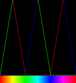
|
Cold-warm cluts
%IMG7%magick ^
xc:#004 xc:#404 xc:#800 xc:#f00 xc:#f80 xc:#ff0 xc:#ffa ^
+append +repage ^
-resize "256x1^!" ^
cl_falseCol.png
call %PICTBAT%graphLineCol cl_falseCol.png
|
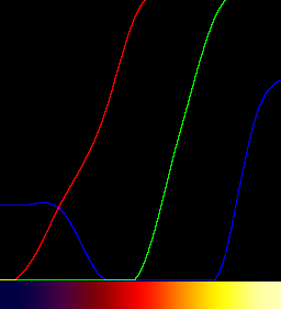
|
The graph shows the channels change at a variable rate; they are curves, not linear. The clut is nearly flat at each end, so distinguishing values by colour is difficult.
The "triangle" filter for resize gives a linear response, but it leaves flat portions at each end.
%IMG7%magick ^
xc:#004 xc:#404 xc:#800 xc:#f00 xc:#f80 xc:#ff0 xc:#ffa ^
+append +repage ^
-filter Triangle ^
-resize "256x1^!" ^
cl_falseCol2.png
call %PICTBAT%graphLineCol cl_falseCol2.png
|
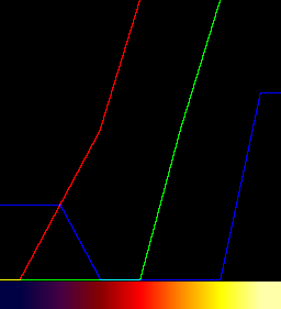
|
We know the width and the colours at each end, so we can fairly easily remove the repetition at the ends.
%IMG7%magick cl_falseCol2.png -flop %TEMP%\cl_flop.png
for /F "usebackq tokens=3 delims=(),@ " %%F in (`%IMG7%magick compare ^
-subimage-search -metric RMSE ^
-similarity-threshold 0 -dissimilarity-threshold 1 ^
%TEMP%\cl_flop.png ^
xc:#004 ^
NULL: 2^>^&1`) DO set /A cl_START=256-%%F
for /F "usebackq tokens=3 delims=(),@ " %%F in (`%IMG7%magick compare ^
-subimage-search -metric RMSE ^
-similarity-threshold 0 -dissimilarity-threshold 1 ^
cl_falseCol2.png ^
xc:#ffa ^
NULL: 2^>^&1`) DO set /A cl_WIDTH=%%F-%cl_START%+2
echo cl_START=%cl_START% cl_WIDTH=%cl_WIDTH%
%IMG7%magick ^
cl_falseCol2.png ^
-crop %cl_WIDTH%x1+%cl_START%+0 +repage ^
cl_falseCol2cr.png
call %PICTBAT%graphLineCol cl_falseCol2cr.png
|
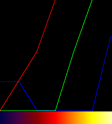
|
We can also get a linear response by using "gradient:", though a value is repeated at every transition. This method enables discontinuities in the clut.
%IMG7%magick ^
-size 1x42 ^
gradient:#004-#404 ^
gradient:#404-#800 ^
gradient:#800-#f00 ^
gradient:#f00-#f80 ^
gradient:#f80-#ff0 ^
gradient:#ff0-#ffa ^
-rotate -90 ^
+append +repage ^
cl_falseCol3.png
call %PICTBAT%graphLineCol cl_falseCol3.png
|

|
A clut doesn't need to be large. Here we create a clut of just seven pixels. When used on a larger image, IM interpolates between the seven values. In this example, the larger image is one pixel high. It, too, is a clut. This method doesn't have the repeated values, so no kinks. But we can't create individual discontinuities. TODO: When is a small clut good enough? Interpolation issues. Apply false colour clut to gradient, with fc clut very small or large.
%IMG7%magick ^
-size 1x256 gradient: -rotate 90 ^
( -size 1x1 ^
xc:#004 xc:#404 xc:#800 xc:#f00 xc:#f80 xc:#ff0 xc:#ffa ^
+append +repage ^
) ^
-clut ^
cl_cl_fc.png
call %PICTBAT%graphLineCol cl_cl_fc.png
|
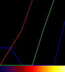
|
We can tell "-clut" how to interpolate between values.
We can process cluts. For example, we might know a few required transformations for colour changes for an image. Perhaps we want black to remain black, white to remain white, and two other values to become rgb(10%,10%,20%) and rgb(85%,80%,55%). We can make a clut of just these four values (note the repeated ends). The transformations need to be sorted. We can "-equalize" the clut to spread tones evenly. When the clut is used, tones in the image won't change.
|
The basic clut.
%IMG7%magick ^
-size 1x256 gradient: -rotate 90 ^
( -size 1x1 ^
xc:black xc:black ^
xc:rgb(10%%,10%%,20%%) xc:rgb(85%%,80%%,55%%) ^
xc:white xc:white ^
+append +repage ^
) ^
-interpolate spline ^
-clut ^
cl_wb1.png
call %PICTBAT%graphLineCol cl_wb1.png
|
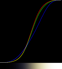
|
|
The equalised clut.
Note the slight glitch at the top.
I suppose this comes from the processing of equalize at maximum values.
%IMG7%magick ^
-size 1x256 gradient: -rotate 90 ^
( -size 1x1 ^
xc:black xc:black ^
xc:rgb(10%%,10%%,20%%) xc:rgb(85%%,80%%,55%%) ^
xc:white xc:white ^
+append +repage ^
) ^
-interpolate spline ^
-clut ^
-equalize ^
cl_wb2.png
call %PICTBAT%graphLineCol cl_wb2.png
|
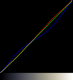
|
The colours could be specified as the required outputs (instead of inputs), then inserting ...
( +clone -colorspace gray ) ^
-compose Mathematics -define compose:args=0,2,-1,0 -composite
... after "-equalize", or before it, or after the "+append".
This technique may be accurate enough for small colour-shifts, much smaller than shown here. However, a required transformation will be placed at an x-value equal to the average of the three channels, but when the clut is used, three different x-values corresponding to the three channels will be looked up.
A more accurate colour transformation clut can be constructed.
Suppose we want rgb(45%,33%,70%) to become gray(60%).
If black stays black, white stays white, and there is only one other transformation, the clut can be a power function: y = xk, so k = log(y)/log(x).
for /F "usebackq" %%L ^
in (`%IMG7%magick identify ^
-format "kR=%%[fx:log(0.6)/log(0.45)]\nkG=%%[fx:log(0.6)/log(0.33)]\nkB=%%[fx:log(0.6)/log(0.70)]" ^
xc:`) ^
do set %%L
%IMG7%magick ^
-size 1x250 gradient: -rotate 90 ^
-channel R -evaluate Pow %kR% ^
-channel G -evaluate Pow %kG% ^
-channel B -evaluate Pow %kB% ^
cl_colt1.png
call %PICTBAT%graphLineCol cl_colt1.png
|
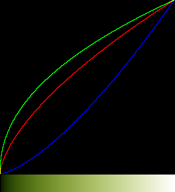
|
|
Compare the above power method with the channel polynomial from cBezCurve:
for /F "usebackq tokens=*" %%F ^
in (`@cBezCurve /p0 /C ^
/I"0,0,0 0,0,0; 0.45,0.33,0.70 0.6,0.6,0.6; 1,1,1 1,1,1" ^
/y-`) ^
do %IMG7%magick ^
-size 1x250 gradient: -rotate 90 ^
%%F ^
cl_colt1a.png
call %PICTBAT%graphLineCol cl_colt1a.png
|
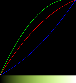
|
|
We can adapt this method for a simple (and fairly useless) displacement, with clipping at both ends.
for /F "usebackq" %%L ^
in (`%IMG7%magick identify ^
-format "dR=%%[fx:100*(0.6-0.45)]\ndG=%%[fx:100*(0.6-0.33)]\ndB=%%[fx:100*(0.6-0.70)]" ^
xc:`) ^
do set %%L
%IMG7%magick ^
-size 1x250 gradient: -rotate 90 ^
-channel R -evaluate Add %dR%%% ^
-channel G -evaluate Add %dG%%% ^
-channel B -evaluate Add %dB%%% ^
cl_colt2.png
call %PICTBAT%graphLineCol cl_colt2.png
|
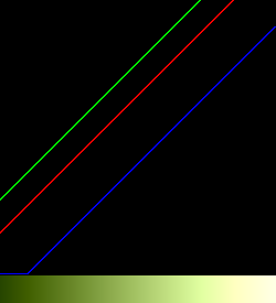
|
Here is a linear transformation. I multiply each x-coordinate by ten to reduce the effect of the doubling. Conceptually simple but messy to code.
|
The resize is only for display on the web page.
%IMG7%magick ^
( -size 450x1 gradient:black-gray(60%%) ^
-size 550x1 gradient:gray(60%%)-white ^
+append +repage ^
) ^
( -size 330x1 gradient:black-gray(60%%) ^
-size 670x1 gradient:gray(60%%)-white ^
+append +repage ^
) ^
( -size 700x1 gradient:black-gray(60%%) ^
-size 300x1 gradient:gray(60%%)-white ^
+append +repage ^
) ^
-combine ^
-set colorspace sRGB ^
-resize "250x1^!" ^
cl_colt3.png
call %PICTBAT%graphLineCol cl_colt3.png
|
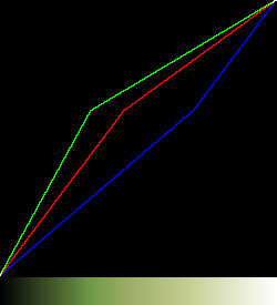
|
This append/combine technique can be extended to any number of transformation points, but creating it by hand would be awkward.
If we are correcting a highlight and we don't care about any lighter tones, the clut can be simpler. This works best when the "gray point" is near white because we get continued diversion at lighter tones, resulting in heavy clipping.
%IMG7%magick ^
-size 1x250 gradient: -rotate 90 ^
-evaluate Multiply 0.6 ^
( +clone -fill rgb(45%%,33%%,70%%) -colorize 100 ) ^
+swap ^
-compose Divide -composite ^
cl_colt4.png
call %PICTBAT%graphLineCol cl_colt4.png
|
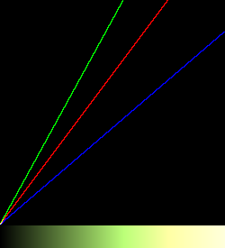
|
A clut can be smoothed.
|
Input: cl_falseCol3.png
|
|
|
%IMG7%magick ^
cl_falseCol3.png ^
-blur 0x10 ^
cl_falseCol4.png
call %PICTBAT%graphLineCol cl_falseCol4.png
|

|
This section describes a script for creating histograms.
Process modules: mkhisto describes a much faster "-process" module in C for the same job.
A cumulative histogram is a clut. Mathematically, the cumulative is the integration of the ordinary histogram. (The ordinary histogram is the differential of the cumulative.)
|
Input: toes.png
|

|
|
Make a histogram the conventional way.
%IMG7%magick ^
toes.png ^
-define histogram:unique-colors=false ^
histogram:cl_toes_hist.png
|
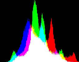
|
|
Make a histogram with a script.
set c2hDO_CUMUL=0
set c2hINBITS=8
call %PICTBAT%col2Histo toes.png
if ERRORLEVEL 1 exit /B 1
call %PICTBAT%graphLineCol %c2hOUTFILE%
|
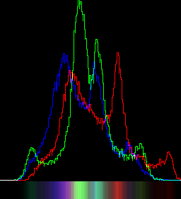
|
|
Make a cumulative histogram with the same script.
set c2hDO_CUMUL=1
call %PICTBAT%col2Histo toes.png cl_toes_cumul.png
if ERRORLEVEL 1 exit /B 1
set c2hDO_CUMUL=
set c2hINBITS=
call %PICTBAT%graphLineCol cl_toes_cumul.png
The cumulative histogram cl_toes_cumul.png is a clut.
|
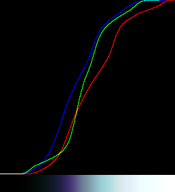
|
We can use a custom program. This might require us to give both the input and output colours. cBezCurve.exe can create a polynomial for each channel directly usable by ImageMagick. The polynomials could be used on the image, or on a clut which is then used to modift the image. The clut technique will generally be faster.
(I don't publish the source or executable of cBezCurve.exe.)
for /F "usebackq tokens=*" %%F ^
in (`@cBezCurve /p0 /C ^
/I"0,0,0 0,0,0; 0.15,0.15,0.15 0.1,0.1,0.2; 0.7,0.7,0.7 0.85,0.80,0.55; 1,1,1 1,1,1" ^
/y-`) ^
do %IMG7%magick ^
-size 1x250 gradient: -rotate 90 ^
%%F ^
cl_cbc1.png
call %PICTBAT%graphLineCol cl_cbc1.png
|
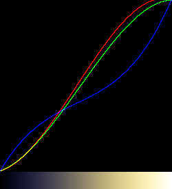
|
for /F "usebackq tokens=*" %%F ^
in (`@cBezCurve /p0 /C ^
/I"0,0,0 0,0,0; gray 0.1,0.1,0.2; gray 0.85,0.80,0.55; 1,1,1 1,1,1" ^
/y-`) ^
do %IMG7%magick ^
-size 1x250 gradient: -rotate 90 ^
%%F ^
cl_cbc2.png
call %PICTBAT%graphLineCol cl_cbc2.png
|
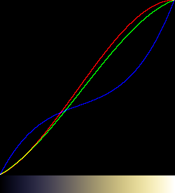
|
cBezCurve.exe can directly make clut files using a variety of methods.
|
Passing through all the points, with linear interpolation along segments between points.
cBezCurve /p0 /C ^
/I"0,0,0 0,0,0; gray 0.1,0.1,0.2; gray 0.85,0.80,0.55; 1,1,1 1,1,1" ^
/T0 /Lcl_cbcc0.ppm
call %PICTBAT%graphLineCol cl_cbcc0.ppm
|
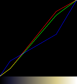
|
|
Bezier spline, passing through all the points.
cBezCurve /p0 /C ^
/I"0,0,0 0,0,0; gray 0.1,0.1,0.2; gray 0.85,0.80,0.55; 1,1,1 1,1,1" ^
/T1 /Lcl_cbcc1.ppm
call %PICTBAT%graphLineCol cl_cbcc1.ppm
|

|
|
Polynomial, passing through all the points.
cBezCurve /p0 /C ^
/I"0,0,0 0,0,0; gray 0.1,0.1,0.2; gray 0.85,0.80,0.55; 1,1,1 1,1,1" ^
/T2 /Lcl_cbcc2.ppm
call %PICTBAT%graphLineCol cl_cbcc2.ppm
|

|
|
Linear regression, the straight line that fits best between points.
cBezCurve /p0 /C ^
/I"0,0,0 0,0,0; gray 0.1,0.1,0.2; gray 0.85,0.80,0.55; 1,1,1 1,1,1" ^
/T3 /Lcl_cbcc3.ppm
call %PICTBAT%graphLineCol cl_cbcc3.ppm
|
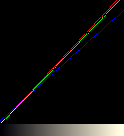
|
Another clut, for use later. The red channel increases; green decreases, blue does both.
|
Bezier spline, passing through all the points.
cBezCurve /p0 /C ^
/I"0,0,0 0,0.8,0; 0.13,0.13,0.13 0.1,0.60,0.55; 0.66,0.66,0.66 0.85,0.25,0.2; 1,1,1 1,0.1,1" ^
/T1 /Lcl_cbcc4.ppm
call %PICTBAT%graphLineCol cl_cbcc4.ppm
|
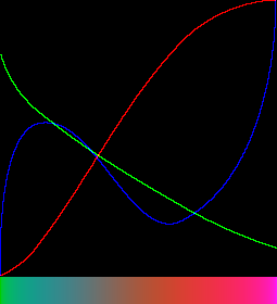
|
Sometimes we want a mask that is white where the image is a certain hue (centHue), and black otherwise. This would be a binary mask: every pixel is either black or white.
We can use HSL or HCL colorspace, so centHue=0 or 100% is red, centHue=33.3% is green, centHue=66.6% is blue, etc. Hue wraps around at 100%, and the clut must behave properly there.
We might want the mask to be white where the hue is within a certain range rangeHue. This is the percentage of hues that will become white. (Those hues between centHue-rangeHue/2 and centHue+rangeHue/2, with wraparound at 0 and 100%.) Other hues will become black. When rangeHue is zero, the mask is white only when the hue is exactly centHue.
Instead of a binary mask, we might want two transitions over a certain range of hues (transHue), so hues just outside centHue-rangeHue/2 and centHue+rangeHue/2 are a shade of gray. When transHue is zero, we get a binary mask. However, IM disregards -level when the levels are equal, so use a small number such as 0.01 instead of zero. A more intelligent script would check for zero, and use -threshold instead.
The code below gives a linear transition. Of course, this can be modified by other methods shown on this page to give a cosine or any other rolloff.
Generally, rangeHue+2*transHue should not exceed 100.
set centHue=33.3
set rangeHue=10
set transHue=20
With these numbers, hues between 28.3% (centHue-rangeHue/2) and 38.3% (centHue+rangeHue/2) will be white, hues below 8.3% (centHue-rangeHue/2-transHue) or above 58.3% (centHue+rangeHue/2+transHue) will be black, and others will be shades of gray.
set sFMT=^
ADD_PC=%%[fx:50-%centHue%]\n^
LEV_HI=%%[fx:100-%rangeHue%]\n^
LEV_LO=%%[fx:100-%rangeHue%-2*%transHue%]
for /F "usebackq" %%L in (`%IMG7%magick identify ^
-format "%sFMT%" ^
xc:`) do set %%L
echo ADD_PC=%ADD_PC% LEV_HI=%LEV_HI% LEV_LO=%LEV_LO%
ADD_PC=16.7 LEV_HI=90 LEV_LO=50
%IMG7%magick ^
-size 1x256 gradient: -rotate 90 ^
-evaluate AddModulus %ADD_PC%%% ^
-solarize 50%% ^
-evaluate Multiply 2 ^
-level %LEV_LO%,%LEV_HI%%% ^
cl_hr1.png
call %PICTBAT%graph1d cl_hr1.png
|

|
|
IM can now do this more directly. See
New -range-threshold operator in IM 7.
%IMG7%magick ^
-size 1x256 gradient: -rotate 90 ^
-range-threshold ^
%%[fx:%centHue%-%rangeHue%/2-%transHue%],^
%%[fx:%centHue%-%rangeHue%/2],^
%%[fx:%centHue%+%rangeHue%/2],^
%%[fx:%centHue%+%rangeHue%/2+%transHue%]%% ^
cl_hr1a.png
call %PICTBAT%graph1d cl_hr1a.png
|

|
LEV_HI is the percentage of hues that will be white, and LEV_LO is the percentage of hues that will not be black.
In v7, we can do the arithmetic within a "magick" command. We must not use a "%" after the first number in "-level".
%IMG7%magick ^
-size 1x256 gradient: -rotate 90 ^
-evaluate AddModulus %%[fx:50-%centHue%]%% ^
-solarize 50%% ^
-evaluate Multiply 2 ^
-level %%[fx:100-%rangeHue%-2*%transHue%],%%[fx:100-%rangeHue%]%% ^
cl_hr1_7.png
call %PICTBAT%graph1d cl_hr1_7.png
|

|
Widen the transition:
set centHue=33.3
set rangeHue=10
set transHue=40
%IMG7%magick ^
-size 1x256 gradient: -rotate 90 ^
-evaluate AddModulus %%[fx:50-%centHue%]%% ^
-solarize 50%% ^
-evaluate Multiply 2 ^
-level %%[fx:100-%rangeHue%-2*%transHue%],%%[fx:100-%rangeHue%]%% ^
cl_hr2_7.png
call %PICTBAT%graph1d cl_hr2_7.png
|

|
Test at red hue (0%):
set centHue=0
set rangeHue=10
set transHue=40
%IMG7%magick ^
-size 1x256 gradient: -rotate 90 ^
-evaluate AddModulus %%[fx:50-%centHue%]%% ^
-solarize 50%% ^
-evaluate Multiply 2 ^
-level %%[fx:100-%rangeHue%-2*%transHue%],%%[fx:100-%rangeHue%]%% ^
cl_hr3_7.png
call %PICTBAT%graph1d cl_hr3_7.png
|

|
The clut can then be applied to the hue channel of an image to make a mask. Alternatively, make the mask by applying the same procedure directly to the hue channel. For example, to lower the saturation of red pixels, (and pixels within plus or minus 5% of red), with a 10% transition range:
set centHue=0
set rangeHue=10
set transHue=10
%IMG7%magick ^
rose: ^
( -clone 0 -modulate 100,0,100 ) ^
( -clone 0 ^
-colorspace HSL ^
-channel H -separate +channel ^
-evaluate AddModulus %%[fx:50-%centHue%]%% ^
-solarize 50%% ^
-evaluate Multiply 2 ^
-level %%[fx:100-%rangeHue%-2*%transHue%],%%[fx:100-%rangeHue%]%% ^
) ^
-compose Over -composite ^
cl_hrrose_7.png
|

|
Cluts can be blurred to create or expand transitions. As they have only one dimension, we use a one-dimensional blur for better performance than the two-dimensional "-blur".
See also
Process modules: invclut, which describes a much faster "-process" module in C for the same job.
A clut transforms an image X into another image X'. Under certain conditions there will exist another clut that will transform X' into X.
Graphically, the clut is the transformation y = f(x). The inverse is x = f'(y).
Inverting a monochrome clut, so the effect is reversed, is fairly simple. We scale it vertically to a square, and compare it to (subtract it from) a vertical gradient with white at the top. Pixels greater than the gradient are made white; others are made black. This is scaled horizontally to make a vertical clut. We rotate it to the horizontal orientation, just like the original clut.
|
cl_sig2.png, created above:
|
|
|
Invert it.
FOR /F "usebackq" %%L ^
IN (`%IMG7%magick identify -format "WW=%%w" cl_sig2.png`) ^
DO set %%L
%IMG7%magick ^
cl_sig2.png ^
-scale "%WW%x%WW%^!" ^
-size %WW%x%WW% gradient:white-black ^
-compose MinusDst -composite ^
-fill #fff +opaque #000 ^
-scale "1x%WW%^!" ^
-rotate 90 ^
cl_sig2_icl.png
call %PICTBAT%graph1d cl_sig2_icl.png
|

|
If the input clut is Nx1 pixels then the output is also Nx1 pixels, and the precision is one part in N. The method creates two intermediate images of NxN pixels, so eats memory when N is large, such as 65536.
We can test the inversion by reading an image, applying the clut, then applying the inverse clut and we should be back where we started. The comparison should be near zero, ie less than 0.01.
%IMG7%magick ^
rose: ^
( +clone ^
cl_sig2.png -clut ^
cl_sig2_icl.png -clut ^
) ^
-metric RMSE ^
-format "%%[distortion]" ^
-compare info:
0.00379816
The first clut can be thought of as a gradient: that has been displaced, so the clut is an absolute displacement map, and the inverse clut gives a reverse displacement. So applying the inverse clut to the first clut should give a gradient:.
%IMG7%magick ^
cl_sig2.png ^
cl_sig2_icl.png -clut ^
( -size 1x%WW% gradient: -rotate 90 ) ^
-metric RMSE ^
-format "%%[distortion]" ^
-compare info:
0.00375274
This simple method works for cluts that increase monotonically, but fails when the clut decreases, ie has a negative slope.
|
cl_exp3.png, created above:
|
|
|
Invert it.
FOR /F "usebackq" %%L ^
IN (`%IMG7%magick identify -format "WW=%%w" cl_exp3.png`) ^
DO set %%L
%IMG7%magick ^
cl_exp3.png ^
-scale "%WW%x%WW%^!" ^
-size %WW%x%WW% gradient: ^
-compose MinusDst -composite ^
-fill #fff +opaque #000 ^
-scale "1x%WW%^!" ^
-rotate 90 ^
cl_exp3_icl.png
call %PICTBAT%graph1d cl_exp3_icl.png
The inversion is wrong.
|

|
|
We cure the problem with a "-negate".
%IMG7%magick ^
cl_exp3.png ^
-scale "%WW%x%WW%^!" ^
-size %WW%x%WW% gradient: ^
-compose MinusDst -composite ^
-fill #fff +opaque #000 ^
-scale "1x%WW%^!" ^
-negate ^
-rotate 90 ^
cl_exp3_icl2.png
call %PICTBAT%graph1d cl_exp3_icl2.png
The inversion is correct.
|

|
Test the inversion:
%IMG7%magick ^
rose: ^
( +clone ^
cl_exp3.png -clut ^
cl_exp3_icl2.png -clut ^
) ^
-metric RMSE ^
-format "%%[distortion]" ^
-compare info:
0.00411898
So we have a solution for cluts that increase and a slightly different solution for cluts that decrease. Where a clut both increases and decreases, multiple x-values yield the same y-value, so no solution is possible.
Inverting a colour clut that increase monotonically is slightly more complicated. We need to "un-sync" the colour channels, so the threshold is applied to each channel independently of the others. We should also (but don't here) test whether each of the three slopes increases or decreases.
|
cl_cbcc2.ppm, created above:
|
|
|
Invert it.
FOR /F "usebackq" %%L ^
IN (`%IMG7%magick identify -format "WW=%%w" cl_cbcc2.ppm`) ^
DO set %%L
%IMG7%magick ^
cl_cbcc2.ppm ^
-scale "%WW%x%WW%^!" ^
-size %WW%x%WW% gradient: ^
-compose MinusDst -composite ^
-channel RGB -threshold 0 +channel ^
-scale "1x%WW%^!" ^
-rotate 90 ^
cl_cbcc2_icl.png
call %PICTBAT%graphLineCol cl_cbcc2_icl.png
|
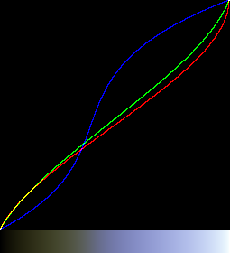
|
Test the inversion:
%IMG7%magick ^
rose: ^
( +clone ^
cl_cbcc2.ppm -clut ^
cl_cbcc2_icl.png -clut ^
) ^
-metric RMSE ^
-format "%%[distortion]" ^
-compare info:
0.00148819
Inverting the awkward clut:
|
cl_cbcc4.ppm, created above:
|
|
|
The green channel decreases, so we have a "-negate" just for this.
FOR /F "usebackq" %%L ^
IN (`%IMG7%magick identify -format "WW=%%w" cl_cbcc4.ppm`) ^
DO set %%L
%IMG7%magick ^
cl_cbcc4.ppm ^
-scale "%WW%x%WW%^!" ^
-size %WW%x%WW% gradient: ^
-compose MinusDst -composite ^
-channel RGB -threshold 0 ^
-channel G -negate ^
+channel ^
-scale "1x%WW%^!" ^
-rotate 90 ^
cl_cbcc4_icx.png
call %PICTBAT%graphLineCol cl_cbcc4_icx.png
|

|
|
Apply the inverse clut to the clut.
FOR /F "usebackq" %%L ^
IN (`%IMG7%magick identify -format "WW=%%w" cl_cbcc4.ppm`) ^
DO set %%L
%IMG7%magick ^
cl_cbcc4.ppm ^
cl_cbcc4_icx.png -clut ^
cl_cbcc4_comp.png
call %PICTBAT%graphLineCol cl_cbcc4_comp.png
We can see the red and green channels have inverted successfully.
Blue has inverted successfully at the ends but not elsewhere.
The blue channel of the clut can't be inverted.
|
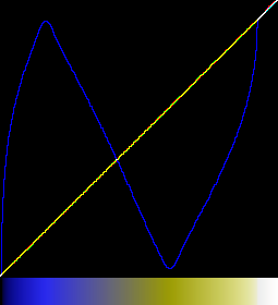
|
For convenience, a script determines whether each channel increases or decreases.
|
cl_cbcc4.ppm, created above:
|
|
|
Calculate the inverse clut with a script.
call %PICTBAT%invClut cl_cbcc4.ppm
call %PICTBAT%graphLineCol cl_cbcc4_icl.png
|
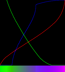
|
The command needs memory for two images that are n*n pixels square. For 8-bit cluts, n=256, and the method works well. For 16-bit cluts, n=65536 so each image needs 34 GB and the processing (on disk) takes 90 minutes.
This covers the inversion of cluts, which can also be thought of as absolute 1-D displacement maps. For the inversion of relative 1-D displacement maps, see
Displacement maps: Inverse displacements.
Another method for inverting cluts uses a process module. See
Process modules: invclut. This works correctly only when the clut increases monotonically.
|
Calculate the inverse clut with a process module.
%IM7DEV%magick ^
cl_cbcc4.ppm ^
-process invclut ^
cl_pm_icl.png
call %PICTBAT%graphLineCol cl_pm_icl.png
|
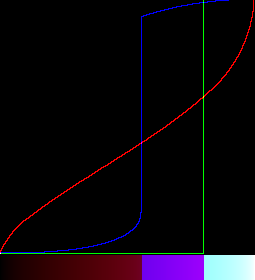
|
The inversion is correct for the red channel, but not for the green or blur channels because they do not increase monotonically.
-clut behaves like the arithmetic operator multiply, and grad.png is the identity, the number 1. invClutA corresponds to 1/clutA.
The following two commands are equivalent:
magick in.png clutA.png -clut clutB.png -clut out.png
magick in.png ( clutA.png clutB.png -clut ) -clut out.png
In words: taking an image, applying a clut, than applying a second clut, is the same as applying the second clut to the first and applying the resulting clut to the image.
(x * A) * B = x * (A * B)
If two or more cluts are performed, the order is not significant. That is, the two commands ...
magick in.png clutA.png -clut clutB.png -clut out1.png
magick in.png clutB.png -clut clutA.png -clut out2.png
... will create the same results.
If invClutA.png is the inverse of clutA.png (see
Inverting cluts above), then ...
magick in.png clutA.png -clut invClutA.png -clut out.png
... makes an output that is the same as the input.
x * A * 1/A = x
If invClutA.png is the inverse of clutA.png, it does not necessarily follow that clutA.png is the inverse of invClutA.png. If clutA.png has a horizontal portion, then multiple inputs define the same output, and the inverse of clutA.png is not invertible.
If grad.png is a horizontal gradient from black to white, the same size as the clut image, then ...
magick grad.png clutA.png -clut out.png
... makes an output that is the same as clutA.png,
1 * A = A
And ....
magick clutA.png grad.png -clut out.png
... also makes an output that is the same as clutA.png.
A * 1 = A
Provided clutA.png always increases (there are no flat portions), then ...
magick clutA.png invClutA.png -clut out.png
... makes an output that is the same as grad.png.
A * 1/A = 1
I will denote the command fragment ...
imageA -process 'mkhisto cumul norm'
... as ...
CH(imageA)
CH(clutA) creates the inverse clut.
CH(clutA) = invclut(clutA)
Provided clutA is invertible, and its inverse is invertible, then:
invclut(invclut(clutA)) = clutA
... so:
invclut(invclut(invclut(clutA))) = invclut(clutA)
For general images, noting that cumulative histograms are always invertible:
CH(invclut(CH(imageA))) = CH(imageA)
In words: if we know the cumulative histogram of an image CH(imageA) then we can takes its inverse, and the cumulative histogram of this inverse is the same as the cumulative histogram of the original image. The inverse CH of an image is a proxy for that image.
We demonstrate the effect of "-interpolate" on a small clut.
First, we make a clut with only four entries and a gradient to test it:
%IMG7%magick ^
xc:black xc:gray(80%%) xc:gray(20%%) xc:white ^
+append +repage ^
cl_cf_clut.miff
%IMG7%magick ^
-size 256x1 gradient:black-white ^
cl_cf_grad.miff
We apply the clut to the gradient, with default interpolation:
%IMG7%magick ^
cl_cf_grad.miff ^
cl_cf_clut.miff ^
-clut ^
cl_cf.png
call %PICTBAT%graphLineCol ^
cl_cf.png . . . cl_cf_null.png
|

|
The default interpolation is bilinear, which gives an abrupt change of gradient at the control points.
To demonstrate all available interpolation settings, we make a montage:
set FILES=
for /F "usebackq" %%F in (`%IMG7%magick -list interpolate`) do (
%IMG7%magick ^
cl_cf_grad.miff ^
cl_cf_clut.miff ^
-interpolate %%F ^
-clut ^
cl_cf.png
call %PICTBAT%graphLineCol cl_cf.png . . . cl_cf_%%F.miff
%IMG7%magick ^
cl_cf_%%F.miff ^
-fill Yellow ^
+antialias ^
-pointsize 25 ^
-gravity NorthWest ^
-annotate 0 "%%F" ^
cl_cf_%%F.miff
set FILES=!FILES! cl_cf_%%F.miff
)
%IMG7%magick montage ^
%FILES% ^
-geometry 256x256+10+10 ^
cl_cf_app.png
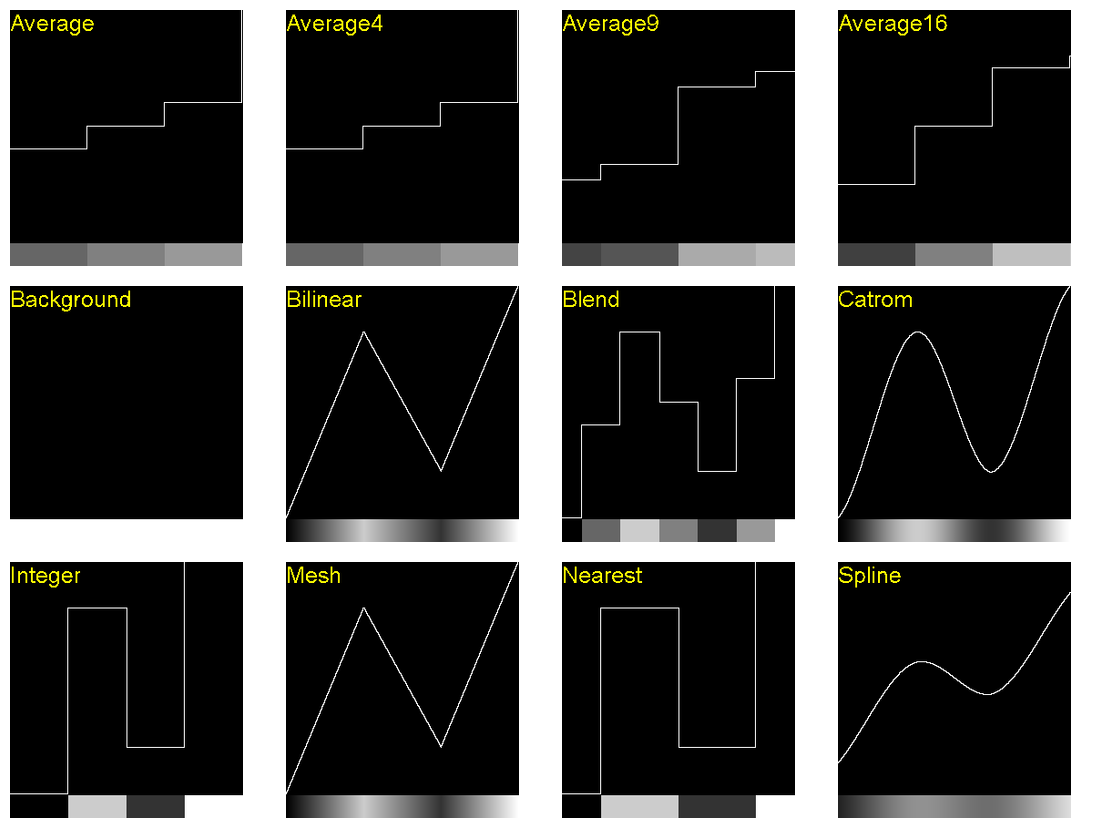
The Catrom setting passes through the control points, with a smooth change of gradient (second-order continuity). We can use this to create cluts that pass through equally-spaced control points:
%IMG7%magick ^
cl_cf_grad.miff ^
( xc:Black xc:gray(75%%) xc:White ^
+append +repage ^
) ^
-interpolate Catrom ^
-clut ^
cl_cf_cat1.png
call %PICTBAT%graphLineCol ^
cl_cf_cat1.png . . . cl_cf_cat1.png
|
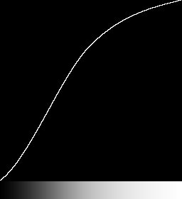
|
%IMG7%magick ^
cl_cf_grad.miff ^
( xc:Black xc:gray(10%%) ^
xc:gray(75%%) xc:White ^
+append +repage ^
) ^
-interpolate Catrom ^
-clut ^
cl_cf_cat2.png
call %PICTBAT%graphLineCol ^
cl_cf_cat2.png . . . cl_cf_cat2.png
|
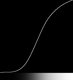
|
%IMG7%magick ^
cl_cf_grad.miff ^
( xc:Black xc:gray(10%%) xc:gray(60%%) ^
xc:gray(90%%) xc:White ^
+append +repage ^
) ^
-interpolate Catrom ^
-clut ^
cl_cf_cat3.png
call %PICTBAT%graphLineCol ^
cl_cf_cat3.png . . . cl_cf_cat3.png
|
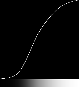
|
See also
Cluts from resize above.
Given an input histogram, we can make an image such that its histogram is equal to the input histogram. Hence the constructed image will have the same distribution of pixel values as the image that was used to make the input histogram.
See
Process modules: Application: de-histogram.
If an image undergoes channel curve manipulations to form a second image, the cumulative histograms (CHs) can be used to transform either image to the other. More usefully, the same transformation can be applied to other images in order to obtain the same effect.
We have created two cluts. One will transform from toes.png to toes_x.jpg. The other will transform in the opposite direction.
|
Apply these to toes and toes_x.
%IMG7%magick ^
toes.png ^
cl_t_ixt.png ^
-clut ^
cl_toes_txit.png
%IMG7%magick ^
toes_x.jpg ^
cl_tx_it.png ^
-clut ^
cl_toes_x_txit.png
|
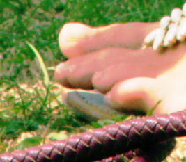
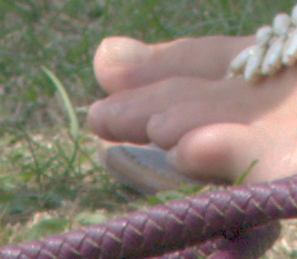
|
Check the results:
%IMG7%magick compare -metric RMSE toes.png cl_toes_x_txit.png NULL:
echo.
%IMG7%magick compare -metric RMSE toes_x.jpg cl_toes_txit.png NULL:
cmd /c exit /B 0
479.977 (0.00732399)310.503 (0.00473798)
Both comparisons are less than 1%. We have created a clut that replicates the transformation we made in Gimp. As a bonus, we also have the inverse transformation.
From the cumulative histograms of two images, we can easily create a clut to transform from one image to the other. Creating these cumulative histograms in a script is a pain. Perhaps it will eventually be built in to ImageMagick.
I think my method is equivalent to Fred Weinhaus's histmatch script. See
Fred's ImageMagick Scripts. My method uses IM tools to make a clut by applying the inverse of one clut to another, where Fred's method uses (in genLutImage()) Unix tools to walk through one CH until the count exceeds the other.
Instead of my scripts above, a faster and more accurate method uses process modules. See
Process modules: Matching histograms.
We can use an Nx1 grayscale image for distortion (warping) in one dimension. For example, suppose we want a horizontal distortion that doesn't move the left or right edges, but moves x-ordinates that are on the right of centre (at x=60%) to a new position at the left of centre of the image (x=40%).
For the source, we use an image with a grid so we can see what is happening.
set DISPSRC=cl_disp_src.png
call %PICTBAT%gridOver ^
toes.png %DISPSRC% 8 8 1 yellow
|
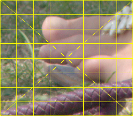
|
We make an absolute displacement map. A power curve keeps 0 at 0 and 100% at 100%, moving some other value to whatever we want. We apply this to a WWx1 image, so we could use -fx without performance worries. In the code, X1 and Y1 refer to the input and output of the Nx1 clut, as proportions of the width, so the value at X1 will be Y1, so input pixels at Y1 will be displaced to output X1.
set X1=0.4
set Y1=0.6
%IMG7%magick ^
%DISPSRC% ^
-set option:WW %%w ^
-set option:HH %%h ^
( -size %%[WW]x1 gradient:black-white ^
-evaluate pow %%[fx:log(%Y1%)/log(%X1%)] ^
-scale "%%[WW]x%%[HH]^!" ^
-channel G ^
-sparse-color bilinear ^
0,0,Black,0,%%[fx:h-1],White ^
+channel ^
) ^
-compose Distort -composite ^
cl_toes_disp1.png
|
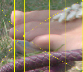
|
Every row is distorted in the same way. Instead, we might want the top and bottom rows to be undistorted. We blend the displacement map with an identity absolute displacement map, using a mask that is black at top and bottom, and graduating to white at y=X2. This modulates the displacement, giving a maximum at y=X2, and no displacement at the image top and bottom.
In the example, we also show the mask.
set X1=0.4
set Y1=0.6
set X2=0.6
%IMG7%magick ^
%DISPSRC% ^
-set option:WW %%w ^
-set option:HH %%h ^
( +clone ^
-sparse-color bilinear ^
0,0,#008,^
%%[fx:w-1],0,#f08,^
0,%%[fx:h-1],#0f8,^
%%[fx:w-1],%%[fx:h-1],#ff8^
+write mpr:IDENT ^
+delete ^
) ^
( -size 1x%%[HH] gradient:black-white ^
-fx "u<%X2%?u/%X2%:1+(u-%X2%)/(%X2%-1)" ^
-scale "%%[WW]x%%[HH]^!" ^
+write mpr:MSK1 ^
+write cl_disp1m_msk1.png ^
+delete ^
) ^
( -size %%[WW]x1 gradient:black-white ^
-evaluate pow %%[fx:log(%Y1%)/log(%X1%)] ^
-scale "%%[WW]x%%[HH]^!" ^
-channel G ^
-sparse-color bilinear ^
0,0,Black,0,%%[fx:h-1],White ^
+channel ^
mpr:IDENT ^
+swap ^
mpr:MSK1 ^
-compose Over -composite ^
) ^
-compose Distort -composite ^
cl_toes_disp1m.png
|

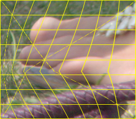
|
Perhaps we don't like the kinks, the abrupt changes of gradient at y=X2. The result is smoother if we transform the map by a curve that has zero gradient at v=1, such as a sinusoid. This also has zero gradient at v=0, so the lines are vertical at the top and bottom:
set X1=0.4
set Y1=0.6
set X2=0.6
%IMG7%magick ^
%DISPSRC% ^
-set option:WW %%w ^
-set option:HH %%h ^
( +clone ^
-sparse-color bilinear ^
0,0,#008,^
%%[fx:w-1],0,#f08,^
0,%%[fx:h-1],#0f8,^
%%[fx:w-1],%%[fx:h-1],#ff8^
+write mpr:IDENT ^
+delete ^
) ^
( -size 1x%%[HH] gradient:black-white ^
-fx "u<%X2%?u/%X2%:1+(u-%X2%)/(%X2%-1)" ^
-function sinusoid 0.5,-90,0.5,0.5 ^
-scale "%%[WW]x%%[HH]^!" ^
+write mpr:MSK1 ^
+write cl_disp1ms_msk1.png ^
+delete ^
) ^
( -size %%[WW]x1 gradient:black-white ^
-evaluate pow %%[fx:log(%Y1%)/log(%X1%)] ^
-scale "%%[WW]x%%[HH]^!" ^
-channel G ^
-sparse-color bilinear ^
0,0,Black,0,%%[fx:h-1],White ^
+channel ^
mpr:IDENT ^
+swap ^
mpr:MSK1 ^
-compose Over -composite ^
) ^
-compose Distort -composite ^
cl_toes_disp1ms.png
|

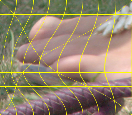
|
Above, we move only in the x-direction. We can extend the method to make a 2D map that also moves in the y-direction. For example, with no modulation of the displacement:
set X1=0.4
set Y1=0.6
set X2=0.6
set Y2=0.4
%IMG7%magick ^
%DISPSRC% ^
-set option:WW %%w ^
-set option:HH %%h ^
( -size %%[WW]x1 gradient:black-white ^
-evaluate pow %%[fx:log(%Y1%)/log(%X1%)] ^
-scale "%%[WW]x%%[HH]^!" ^
) ^
( -size 1x%%[HH]x1 gradient:black-white ^
-evaluate pow %%[fx:log(%Y2%)/log(%X2%)] ^
-scale "%%[WW]x%%[HH]^!" ^
) ^
( +clone ^
-evaluate Set 50%% ^
) ^
( -clone 1-3 ^
-combine ^
) ^
-delete 1-3 ^
-compose Distort -composite ^
cl_toes_disp2.png
|
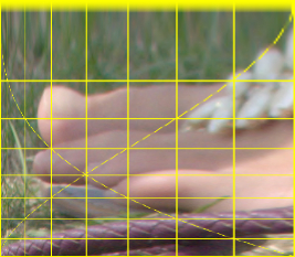
|
A clut can be used as a temporal transformation for animation, eg to transform a linear motion into a smooth start/stop motion. The x-dimension of a horizontal clut represents time. The pixel value represents a transformed time, eg for a smooth start and stop.
Alternatively, the clut may be a spatial transformation, so the pixel value represents an x-coordinate, or the values in two channels represent x- and y-coordinates.
Given a clut, we want to look up entry pr (where 0 <= pr <= 1). If the animation has n frames excluding the final frame, for frame i (where 0 <= i <= n to include the final frame or 0 <= i <= n-1 to exclude it), pr = i/n. We lookup pixel x-coordinate = pr * width.
for /F "usebackq" %%L ^
in (`%IMG7%magick %1 -format "PRT=%%[fx:p{pr*w,pr*h}.r]" info:`) ^
do set %%L
As an example, we make a clut with a sine function and cosine function, which define movement in a circle. But we distort the gradient before calculating sine and cos, and this warps time. We then clone, flop and append to repeat the movement backwards.
%IMG7%magick ^
-size 1x256 gradient: -rotate 90 ^
-sigmoidal-contrast 10x50%% ^
-channel R -evaluate sin 1 ^
-channel G -evaluate cos 1 ^
+channel ^
( +clone -flop ) ^
+append +repage ^
cl_sincos.png
call %PICTBAT%graphLineCol cl_sincos.png
|
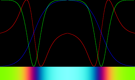
|
The red channel defines the horizontal motion; the green channel defines the vertical motion. The blue channel is not used.
If NUM_FRAMES is the number of frames in a motion excluding the final frame:
set NUM_FRAMES=200
set DIAM=200
set /A nfm1=%NUM_FRAMES%-1
set ANIM_LIST=cl_anim.lis
set FRAME_LIST=cl_anim_frames.lis
del %ANIM_LIST% 2>nul
del %FRAME_LIST% 2>nul
for /L %%i in (0,1,%nfm1%) do (
set sFRAME=00000%%i
set sFRAME=!sFRAME:~-6!
for /F "usebackq" %%L in (`%IMG7%magick ^
cl_sincos.png ^
-format "X=%%[fx:%DIAM%*p{w*%%i/%NUM_FRAMES%,h*%%i/%NUM_FRAMES%}.r]\nY=%%[fx:%DIAM%*p{w*%%i/%NUM_FRAMES%,h*%%i/%NUM_FRAMES%}.g]" ^
info:`) do set %%L
echo %%i !sFRAME! !X! !Y! >>%ANIM_LIST%
set FNAME=%TEMP%\cl_frame_!sFRAME!.png
%IMG7%magick -size 200x200 xc:blue ^
-fill Yellow -draw "translate !X!,!Y! circle 0,0 0,10" ^
!FNAME!
echo !FNAME! >>%FRAME_LIST%
)
rem %IMG7%magick -loop 0 @%FRAME_LIST% cl_anim.gif
call %PICTBAT%blendFrames cl_anim_frames.lis 3 cl_anim_frames2.lis
%IMG7%magick -loop 0 @cl_anim_frames2.lis cl_anim2.gif
0 000000 100.002 200
1 000001 100.449 200
2 000002 100.942 199.997
3 000003 101.485 199.989
4 000004 102.085 199.978
5 000005 102.749 199.962
6 000006 103.479 199.939
7 000007 104.285 199.909
8 000008 105.175 199.866
9 000009 106.152 199.81
10 000010 107.232 199.738
11 000011 108.418 199.645
12 000012 109.723 199.526
13 000013 111.159 199.374
14 000014 112.733 199.186
15 000015 114.465 198.948
16 000016 116.356 198.653
17 000017 118.435 198.285
18 000018 120.701 197.832
19 000019 123.179 197.275
20 000020 125.874 196.595
21 000021 128.802 195.761
22 000022 131.975 194.748
23 000023 135.399 193.524
24 000024 139.09 192.039
25 000025 143.035 190.268
26 000026 147.247 188.129
27 000027 151.698 185.597
28 000028 156.38 182.584
29 000029 161.253 179.038
30 000030 166.27 174.88
31 000031 171.369 170.032
32 000032 176.465 164.438
33 000033 181.446 157.998
34 000034 186.194 150.699
35 000035 190.526 142.446
36 000036 194.289 133.275
37 000037 197.262 123.164
38 000038 199.235 112.191
39 000039 199.984 100.458
40 000040 199.263 88.1196
41 000041 196.924 75.4056
42 000042 192.701 62.5904
43 000043 186.592 50.0058
44 000044 178.447 38.0445
45 000045 168.392 27.0817
46 000046 156.511 17.5391
47 000047 143.057 9.78897
48 000048 128.363 4.12726
49 000049 112.812 0.873548
50 000050 96.8795 0.0488289
51 000051 81.0447 1.86233
52 000052 65.768 6.06149
53 000053 51.5203 12.5836
54 000054 38.6465 21.0736
55 000055 27.4504 31.2151
56 000056 18.1447 42.6217
57 000057 10.7769 54.8694
58 000058 5.43587 67.5873
59 000059 1.94266 80.4031
60 000060 0.273442 92.9958
61 000061 0.146487 105.126
62 000062 1.40298 116.575
63 000063 3.79376 127.22
64 000064 7.09667 136.972
65 000065 11.111 145.776
66 000066 15.6227 153.665
67 000067 20.4798 160.611
68 000068 25.5171 166.723
69 000069 30.6266 172.01
70 000070 35.7043 176.582
71 000071 40.6715 180.493
72 000072 45.4729 183.82
73 000073 50.0699 186.64
74 000074 54.4273 189.007
75 000075 58.5397 191
76 000076 62.3823 192.65
77 000077 65.9691 194.03
78 000078 69.2948 195.166
79 000079 72.3705 196.107
80 000080 75.2074 196.877
81 000081 77.8144 197.506
82 000082 80.2083 198.023
83 000083 82.3976 198.438
84 000084 84.4027 198.778
85 000085 86.23 199.047
86 000086 87.899 199.264
87 000087 89.4168 199.439
88 000088 90.8005 199.576
89 000089 92.0583 199.685
90 000090 93.2009 199.768
91 000091 94.2423 199.834
92 000092 95.1821 199.884
93 000093 96.038 199.922
94 000094 96.8148 199.948
95 000095 97.5174 199.968
96 000096 98.156 199.983
97 000097 98.7332 199.992
98 000098 99.2575 199.997
99 000099 99.7315 200
100 000100 100.002 200
101 000101 99.5511 200
102 000102 99.0584 199.997
103 000103 98.5154 199.989
104 000104 97.9151 199.978
105 000105 97.2506 199.962
106 000106 96.5205 199.939
107 000107 95.7152 199.909
108 000108 94.8253 199.866
109 000109 93.848 199.81
110 000110 92.7675 199.738
111 000111 91.5823 199.645
112 000112 90.2768 199.526
113 000113 88.841 199.374
114 000114 87.2672 199.186
115 000115 85.5354 198.948
116 000116 83.6437 198.653
117 000117 81.5655 198.285
118 000118 79.2994 197.832
119 000119 76.8214 197.275
120 000120 74.1265 196.595
121 000121 71.1982 195.761
122 000122 68.0247 194.748
123 000123 64.6006 193.524
124 000124 60.9105 192.039
125 000125 56.965 190.268
126 000126 52.7528 188.129
127 000127 48.3019 185.597
128 000128 43.6201 182.584
129 000129 38.7468 179.038
130 000130 33.7304 174.88
131 000131 28.6307 170.032
132 000132 23.5353 164.438
133 000133 18.5535 157.998
134 000134 13.8064 150.699
135 000135 9.47402 142.446
136 000136 5.7109 133.275
137 000137 2.7382 123.164
138 000138 0.765393 112.191
139 000139 0.0156252 100.458
140 000140 0.736706 88.1196
141 000141 3.07622 75.4056
142 000142 7.29882 62.5904
143 000143 13.4076 50.0058
144 000144 21.5527 38.0445
145 000145 31.6081 27.0817
146 000146 43.4892 17.5391
147 000147 56.9428 9.78897
148 000148 71.6366 4.12726
149 000149 87.1883 0.873548
150 000150 103.12 0.0488289
151 000151 118.955 1.86233
152 000152 134.232 6.06149
153 000153 148.48 12.5836
154 000154 161.354 21.0736
155 000155 172.55 31.2151
156 000156 181.855 42.6217
157 000157 189.223 54.8694
158 000158 194.564 67.5873
159 000159 198.057 80.4031
160 000160 199.727 92.9958
161 000161 199.854 105.126
162 000162 198.597 116.575
163 000163 196.206 127.22
164 000164 192.903 136.972
165 000165 188.889 145.776
166 000166 184.377 153.665
167 000167 179.52 160.611
168 000168 174.483 166.723
169 000169 169.373 172.01
170 000170 164.296 176.582
171 000171 159.328 180.493
172 000172 154.527 183.82
173 000173 149.93 186.64
174 000174 145.573 189.007
175 000175 141.46 191
176 000176 137.618 192.65
177 000177 134.031 194.03
178 000178 130.705 195.166
179 000179 127.63 196.107
180 000180 124.793 196.877
181 000181 122.186 197.506
182 000182 119.792 198.023
183 000183 117.602 198.438
184 000184 115.594 198.778
185 000185 113.77 199.047
186 000186 112.101 199.264
187 000187 110.583 199.439
188 000188 109.2 199.576
189 000189 107.942 199.685
190 000190 106.799 199.768
191 000191 105.758 199.834
192 000192 104.818 199.884
193 000193 103.962 199.922
194 000194 103.185 199.948
195 000195 102.483 199.968
196 000196 101.844 199.983
197 000197 101.267 199.992
198 000198 100.743 199.997
199 000199 100.268 200
The motion blur comes from temporal supersampling.
For convenience, .bat scripts are also available in a single zip file. See
Zipped BAT files.
I visualise cluts with scripts graph1d.bat and graphLineCol.bat.
rem From image %1 with height=1,
rem makes a graph with same width but max height=256.
@rem
@rem Optional:
@rem %2 is background colour (default Khaki).
@rem %3 is grid (default 0 = no grid).
@rem %4 is output filename.
@rem %5 border colour ("none" = no border) [blue]
@rem
@rem Updated:
@rem 11 March 2017 Simplified.
@rem 20 June 2017 Restored gradient in output.
@rem 8-August-2022 for IM v7.
@rem
@if "%1"=="" findstr /B "rem @rem" %~f0 & exit /B 1
@setlocal
@call echoOffSave
call %PICTBAT%setInOut %1 g1d
set BACKCOL=%2
if "%BACKCOL%"=="." set BACKCOL=
if "%BACKCOL%"=="" set BACKCOL=Khaki
set GRID_SPEC=%3
if "%GRID_SPEC%"=="." set GRID_SPEC=
if "%GRID_SPEC%"=="" set GRID_SPEC=0
if not "%4"=="" if not "%4"=="." set OUTFILE=%4
set BORDCOL=%5
if "%BORDCOL%"=="." set BORDCOL=
if "%BORDCOL%"=="" set BORDCOL=blue
for /F "usebackq" %%L ^
in (`%IMG7%magick identify -format "WW=%%w\nHH=%%h" %INFILE%`) ^
do set %%L
set S_RESIZE=
if %WW% GTR 1000 (
set S_RESIZE=-resize 1000x%HH%
set WW=1000
)
set newH=256
if %WW% LSS 256 (
set newH=%WW%
)
set S_GRID=
if not %GRID_SPEC%==0 (
call %PICTBAT%grid %WW% %newH% 4 3 1
set S_GRID=grid.png -compose Exclusion -composite
)
echo %0: WW=%WW% HH=%HH% newH=%newH% OUTFILE=%OUTFILE%
set /A newH4=4*%newH%
set BRDR=
if /I not "%BORDCOL%"=="none" set BRDR=-bordercolor %BORDCOL% -compose Over -border 1x1
%IMG7%magick ^
%INFILE% ^
-scale "%WW%x1^!" ^
-scale "%WW%x%newH4%^!" ^
+write mpr:SCLE ^
-size %WW%x%newH4% gradient: ^
-compose MinusDst -composite ^
-threshold 0 ^
-negate ^
mpr:SCLE ^
+swap ^
-compose CopyOpacity -composite ^
-resize "%WW%x%newH%^!" ^
-background %BACKCOL% ^
-compose Over -layers Flatten ^
%S_GRID% ^
%BRDR% ^
%OUTFILE%
call echoRestore
@rem From image %1 with height=1, makes a line graph with same width but max height=256.
@rem %2 is background colour, can be "none" (default Khaki).
@rem %3 is grid (default 0 = no grid).
@rem %4 is line colour (default Black).
@rem
@rem Updated:
@rem 25-September-2022 for IM v7.
@rem
@if "%1"=="" findstr /B "rem @rem" %~f0 & exit /B 1
@setlocal
@call echoOffSave
call %PICTBAT%setInOut %1 gl
set BACKCOL=%2
if "%BACKCOL%"=="" set BACKCOL=Khaki
set GRID_SPEC=%3
if "%GRID_SPEC%"=="" set GRID_SPEC=0
set LINECOL=%4
if "%LINECOL%"=="" set LINECOL=Black
FOR /F "usebackq" %%L IN (`%IMG7%magick identify -format "WW=%%w\nHH=%%h" %INFILE%`) DO set %%L
set S_RESIZE=
if %WW% GTR 1000 (
set S_RESIZE=-resize 1000x%HH%
set WW=1000
)
set newH=256
if %WW% LSS 256 (
set newH=%WW%
)
set S_GRID=
if not %GRID_SPEC%==0 (
call %PICTBAT%grid %WW% %newH% 4 3 1
set S_GRID=grid.png -compose Exclusion -composite
)
set /A newH4=4*%newH%
if /I %BACKCOL%==none (
set sBACK=-alpha set -channel RGBA -evaluate set 0
) else (
set sBACK=-fill %BACKCOL% -colorize 100
)
set sBORD=-bordercolor Black -border 1x1
set sBORD=
set LINE_IMG=-clone 0 -scale "%WW%x%newH4%^^^!" ^
-size %WW%x%newH4% gradient: ^
-compose MinusDst -composite ^
-fill #fff +opaque #000 ^
-resize "%WW%x%newH%^^^!" ^
-morphology edgeout diamond:1 ^
-alpha off
if /I %BACKCOL%==none (
%IMG7%magick ^
%INFILE% ^
-scale "%WW%x1^!" ^
-scale "%WW%x%newH%^!" ^
^( -clone 0 ^
-fill %LINECOL% -colorize 100 ^
^) ^
^( %LINE_IMG% ^) ^
-delete 0 ^
-alpha off ^
-compose CopyOpacity -composite ^
%S_GRID% ^
%sBORD% ^
%OUTFILE%
) else (
%IMG7%magick ^
%INFILE% ^
-scale "%WW%x1^!" ^
-scale "%WW%x%newH%^!" ^
^( -clone 0 ^
%sBack% ^
^) ^
^( -clone 0 ^
-fill %LINECOL% -colorize 100 ^
-alpha off ^
^) ^
^( %LINE_IMG% ^) ^
-delete 0 ^
-compose Over -composite ^
%S_GRID% ^
%sBORD% ^
%OUTFILE%
)
:end
call echoRestore
rem From image %1 with height=1,
rem makes a colour line graph with same width but max height=256.
@rem
@rem Optional:
@rem %2 is background colour, can be "none" (default Black).
@rem %3 is grid (default 0 = no grid).
@rem %4 is whether to show clut below graph (default 1 = do show).
@rem %5 output file
@rem %6 limit output width [1000]
@rem %7 graph height [256]
@rem %8 post-processing eg "-compose Over -bordercolor #888 -border 5"
@rem
@rem Also uses:
@rem glcCLUT a process to apply to the clut image only,
@rem eg "-set colorspace RGB -colorspace sRGB"
@rem glcSHOW_STEPS if not blank or 0, add stepped sampler.
@rem
@rem Updated:
@rem 15-May-2016 to use "-layers flatten".
@rem 13-October-2016 Fixed bug in OUTFILE.
@rem 16-February-2021 Added parameter %7.
@rem 21-July-2021 Added "+repage" after "-append".
@rem 8-April-2022 Added glcCLUT.
@rem 14-April-2022 Changed "convert" to "magick".
@rem 21-November-2022 Added glcXscale output.
@if "%1"=="" findstr /B "rem @rem" %~f0 & exit /B 1
@setlocal disabledelayedexpansion
@rem Otherwise ! in LINE_IMG causes IM to misread.
@call echoOffSave
rem Can't use setInOut.
rem call %PICTBAT%setInOut %1 glc
set INFILE=%1
set OUTFILE=%~dpn1_glc.png
if not exist %INFILE% (
%0: can't find INFILE [%INFILE%]
exit /B 1
)
set BACKCOL=%2
if "%BACKCOL%"=="." set BACKCOL=
if "%BACKCOL%"=="" set BACKCOL=#000
set GRID_SPEC=%3
if "%GRID_SPEC%"=="." set GRID_SPEC=
if "%GRID_SPEC%"=="" set GRID_SPEC=0
set SHOW_CLUT=%4
if "%SHOW_CLUT%"=="." set SHOW_CLUT=
if "%SHOW_CLUT%"=="" set SHOW_CLUT=1
set sOUT=%5
if "%sOUT%"=="." set sOUT=
if "%sOUT%"=="" set sOUT=%OUTFILE%
set OUTFILE=%sOUT%
set LIM_WW=%6
if "%LIM_WW%"=="." set LIM_WW=
if "%LIM_WW%"=="" set LIM_WW=1000
if "%glcSHOW_STEPS%"=="" set glcSHOW_STEPS=0
set WW=
FOR /F "usebackq" %%L IN (`%IMG7%magick identify ^
-precision 15 ^
-format "WW=%%w\nHH=%%h\nXscale=%%[fx:%LIM_WW%/w]\n" ^
%INFILE%`) DO set %%L
if "%WW%"=="" exit /B 1
if %WW% GTR %LIM_WW% (
set WW=%LIM_WW%
) else (
set Xscale=1
)
echo %0: Xscale=%Xscale%
set newH=%7
if "%newH%"=="." set newH=
if "%newH%"=="" set newH=256
if %WW% LSS %newH% (
set newH=%WW%
)
set sPOSTPROC=%~8
if "%sPOSTPROC%"=="." set sPOSTPROC=
echo %0: sPOSTPROC=%sPOSTPROC%
if %GRID_SPEC%==0 (
set S_GRID=
) else (
call %PICTBAT%grid %WW% %newH% 10 10 . gray50
set S_GRID=grid.png -compose Exclusion -composite
)
if not "%glcGRID_IMG%"=="" (
set S_GRID=%glcGRID_IMG% -compose Exclusion -composite
)
echo %0: S_GRID=%S_GRID%
rem set /A newH4=4*%newH%
set /A newH4=%newH%
if /I %BACKCOL%==none (
set sBACK=
) else (
set sBACK=-background %BACKCOL% -compose Over -flatten
)
set sBACK=-background %BACKCOL%
echo %0: sBACK=%sBACK%
set LINE_IMG=^
-separate +channel -scale "%WW%x%newH4%^!" ^
-size %WW%x%newH4% gradient: ^
-compose MinusDst -composite ^
-fill #fff +opaque #000 ^
-edge 1
rem -morphology edgeout diamond:1 +write o1.png
rem -canny 0x0.5+10%%+30%%
rem -edge 3
rem -scale "%WW%x%newH%^!" +write o2.png
set /A SHOW_CLUT_HT=%WW%/10
if %SHOW_CLUT_HT% LSS 25 set SHOW_CLUT_HT=25
set STEPS_IMG=%TEMP%\glc_steps.miff
if %glcSHOW_STEPS%==0 (
set STEPS_IMG=
) else (
if %SHOW_CLUT%==0 (
set STEPS_IMG=
) else (
%IMG7%magick ^
%INFILE% ^
-crop %glcSHOW_STEPS%x1@ +repage -scale "1x1^!" +append +repage ^
-define quantum:format=floating-point -depth 32 ^
%glcCLUT% -scale "%WW%x%SHOW_CLUT_HT%^!" ^
%STEPS_IMG%
)
)
if %SHOW_CLUT%==0 (
set sCLUT=
) else (
set sCLUT= ^( mpr:INP %glcCLUT% -scale "%WW%x%SHOW_CLUT_HT%^!" ^) %STEPS_IMG% -append +repage
)
echo %0: sCLUT=%sCLUT%
%IMG7%magick ^
"%INFILE%" -clamp +write mpr:INP ^
-colorspace sRGB ^
-scale "%WW%x1^!" ^
-scale "%WW%x%newH%^!" ^
( -clone 0 ^
( -clone 0 ^
-fill #f00 -colorize 100 ^
) ^
( -clone 0 -channel R %LINE_IMG% ) ^
-delete 0 ^
-alpha off ^
-compose CopyOpacity -composite ^
) ^
( -clone 0 ^
( -clone 0 ^
-fill #0f0 -colorize 100 ^
) ^
( -clone 0 -channel G %LINE_IMG% ) ^
-delete 0 ^
-alpha off ^
-compose CopyOpacity -composite ^
) ^
( -clone 0 ^
( -clone 0 ^
-set colorspace sRGB ^
-fill #00f -colorize 100 ^
) ^
( -clone 0 -channel B %LINE_IMG% ) ^
-delete 0 ^
-alpha off ^
-compose CopyOpacity -composite ^
) ^
-delete 0 ^
%sBACK% ^
-compose Add -layers Flatten ^
-alpha opaque ^
%S_GRID% ^
%sPOSTPROC% ^
%sCLUT% ^
%OUTFILE%
if ERRORLEVEL 1 (
echo %0: magick failed
exit /B 1
)
call echoRestore
endlocal & set glcOUTFILE=%OUTFILE%& set glcXscale=%Xscale%
rem %1 output filename
rem %2 output width, pixels [4096]
rem %3 a, an input fraction [0.5]
rem %4 b, an output fraction [0.5]
rem %5 s, slope at both ends
rem %6 E, contrast strength, > 0
@rem 1 for straight line,
@rem >1 increases contrast at mid point
@rem <1 decreases contrast at mid point
@rem Values v and 1/v are symmetrical.
@rem
@rem Inflection is at (a,b).
@rem
@rem Also uses:
@rem mscPREPROC IM process applied to input linear grayscale
@rem mscPOSTPROC IM process applied to output
@rem
@rem Updated:
@rem 24-August-2022 for IM v7.
@rem
@if "%1"=="" findstr /B "rem @rem" %~f0 & exit /B 1
@setlocal enabledelayedexpansion
@call echoOffSave
call %PICTBAT%setInOut %1 msc
if not "%1"=="" if not "%1"=="." set OUTFILE=%1
set WW=%2
if "%WW%"=="." set WW=
if "%WW%"=="" set WW=4096
set a=%3
if "%a%"=="." set a=
if "%a%"=="" set a=0.5
set b=%4
if "%b%"=="." set b=
if "%b%"=="" set b=0.5
set s=%5
if "%s%"=="." set s=
if "%s%"=="" set s=1
set E=%6
if "%E%"=="." set E=
if "%E%"=="" set E=3
set a1=(1-%a%)
set s1=(1-%s%)
set sa=%s%*%a%
set sa1=%s%*%a1%
set LR=log(%b%)/log(%a%)
set LR1=log(1-%b%)/log(1-%a%)
for /F "usebackq" %%L in (`%IMG7%magick identify
-precision 15 ^
-format "a1=%%[fx:%a1%]\ns1=%%[fx:%s1%]\nsa=%%[fx:%sa%]\nsa1=%%[fx:%sa1%]" ^
xc:`) do set %%L
for /F "usebackq" %%L in (`%IMG7%magick identify
-precision 15 ^
-format "LR=%%[fx:%LR%]\nLR1=%%[fx:%LR1%]" ^
xc:`) do set %%L
%IMG7%magick -size 1x%WW% gradient: -rotate 90 ^
%mscPREPROC% ^
-fx "u<%a%?pow(%s1%*u+%sa%*pow(u/%a%,%E%),%LR%):1-pow(%s1%*(1-u)+%sa1%*pow((1-u)/%a1%,%E%),%LR1%)" ^
%mscPOSTPROC% ^
%OUTFILE%
rem call %PICTBAT%graph1d %OUTFILE%
call echoRestore
@endlocal
rem %1 input image
rem %2 output
rem %3 fulcrum F
rem %4 gradient G at (F,F).
@rem
@rem Updated:
@rem 25-September-2022 for IM v7.
@rem
@if "%1"=="" findstr /B "rem @rem" %~f0 & exit /B 1
@setlocal enabledelayedexpansion
@call echoOffSave
call %PICTBAT%setInOut %1 ful
if not "%2"=="" if not "%2"=="." set OUTFILE=%2
set F=%3
if "%F%"=="." set F=
if "%F%"=="" set F=0.15
set G=%4
if "%G%"=="." set G=
if "%G%"=="" set G=2.0
%IMG7%magick ^
%INFILE% ^
-fx "u<%F%?(0.5*u+0.5*%F%*pow(u/%F%,%G%)):1-(0.5*(1-u)+0.5*(1-%F%)*pow((1-u)/(1-%F%),%G%))" ^
%OUTFILE%
call echoRestore
@endlocal & set fulOUTFILE=%OUTFILE%
rem %1 input image
rem %2 output
rem %3 fulcrum F
rem %4 gradient G at (F,F).
@rem
@rem Updated:
@rem 25-September-2022 for IM v7.
@rem
@if "%1"=="" findstr /B "rem @rem" %~f0 & exit /B 1
@setlocal enabledelayedexpansion
@call echoOffSave
call %PICTBAT%setInOut %1 ful
if not "%2"=="" if not "%2"=="." set OUTFILE=%2
set F=%3
if "%F%"=="." set F=
if "%F%"=="" set F=0.15
set G=%4
if "%G%"=="." set G=
if "%G%"=="" set G=2.0
%IMG7%magick ^
%INFILE% ^
-fx "u<%F%?(%F%*pow(u/%F%,%G%)):1-((1-%F%)*pow((1-u)/(1-%F%),%G%))" ^
%OUTFILE%
call echoRestore
@endlocal & set fulOUTFILE=%OUTFILE%
rem %1 output filename
rem %2 output width, pixels [4096]
rem %3 quoted coords of start of linear portion x0,y0
rem %4 quoted coords of end of linear portion x1,y1
rem %5 s, slope at both ends
rem %6 if not "." or blank, use this as gradient insead of dy/dx.
@rem
@rem Inflection is at (a,b).
@rem
@rem Also uses:
@rem mplpPREPROC IM process applied to input
@rem mplpPOSTPROC IM process applied to output
@rem
@rem Updated:
@rem 15-August-2021 Calculate p and p1 separately, in case points coincide.
@rem 9-September-2021 Treat negative gradient specially.
@rem 2-October-2022 for IM v7.
@rem
@if "%1"=="" findstr /B "rem @rem" %~f0 & exit /B 1
@setlocal enabledelayedexpansion
@call echoOffSave
call %PICTBAT%setInOut %1 mplp
if not "%1"=="" if not "%1"=="." set OUTFILE=%1
set WW=%2
if "%WW%"=="." set WW=
if "%WW%"=="" set WW=4096
set x0y0=%3
if [%x0y0%]==[.] set x0y0=
if [%x0y0%]==[,] set x0y0=
if [%x0y0%]==[] set x0y0="0.2,0.1"
call parseCommaList %x0y0% num x0y0
if not "%num%"=="2" (
echo %0: x0y0 num=%num%
exit /B 1
)
set x1y1=%4
if [%x1y1%]==[.] set x1y1=
if [%x1y1%]==[,] set x1y1=
if [%x1y1%]==[] set x1y1="0.8,0.9"
call parseCommaList %x1y1% num x1y1
if not "%num%"=="2" (
echo %0: x1y1 num=%num%
exit /B 1
)
set s=%5
if "%s%"=="." set s=
if "%s%"=="" set s=1
set forceGrad=%6
if "%forceGrad%"=="." set forceGrad=
set x0=%x0y0[0]%
set y0=%x0y0[1]%
set x1=%x1y1[0]%
set y1=%x1y1[1]%
echo %0: (%x0%,%y0%) (%x1%,%y1%) s=%s%
:: If x0>x1, swap the ends.
::
for /F "usebackq" %%L in (`%IMG7%magick identify
-format "DoSwap=%%[fx:%x0%>%x1%?1:0]\n" ^
xc:`) do set %%L
if %DoSwap%==1 (
set t=%x0%
set x0=%x1%
set x1=!t!
set t=%y0%
set y0=%y1%
set y1=!t!
)
:: FIXME: for forceGrad
for /F "usebackq" %%L in (`%IMG7%magick identify
-format "IsGradNeg=%%[fx:%y0%>%y1%?1:0]\n" ^
xc:`) do set %%L
if %IsGradNeg%==1 (
set FMT=^
x0a=%%[fx:1-%x1%]\n^
x1a=%%[fx:1-%x0%]\n^
y0a=%%[fx:%y1%]\n^
y1a=%%[fx:%y0%]\n
for /F "usebackq" %%L in (`%IMG7%magick identify
-precision 15 ^
-format "!FMT!" ^
xc:`) do set %%L
set sFLOP=-flop
) else (
set x0a=%x0%
set x1a=%x1%
set y0a=%y0%
set y1a=%y1%
set sFLOP=
)
echo %0: (%x0a%,%y0a%) (%x1a%,%y1a%) s=%s%
if "%forceGrad%"=="" (
set "E=%x1a%-%x0a%==0?1:(%y1a%-%y0a%)/(%x1a%-%x0a%)"
for /F "usebackq" %%L in (`%IMG7%magick identify
-precision 15 ^
-format "E=%%[fx:!E!]\n" ^
xc:`) do set %%L
if ERRORLEVEL 1 exit /B 1
) else (
set E=%forceGrad%
)
:: In p or p1 calcs, div by zero means we don't have that power curve.
for /F "usebackq" %%L in (`%IMG7%magick identify
-precision 15 ^
-format "p=%%[fx:%x0a%*%E%/%y0a%]\n" ^
xc:`) do set %%L
if "%p%"=="" set p=0
for /F "usebackq" %%L in (`%IMG7%magick identify
-precision 15 ^
-format "p1=%%[fx:(1-%x1a%)*%E%/(1-%y1a%)]\n" ^
xc:`) do set %%L
if "%p1%"=="" set p1=0
for /F "usebackq" %%L in (`%IMG7%magick identify
-precision 15 ^
-format "a=%%[fx:%y0a%/pow(%x0a%,%p%)]\na1=%%[fx:(1-%y1a%)/pow((1-%x1a%),%p1%)]\n" ^
xc:`) do set %%L
echo %0: E=%E% p=%p% a=%a% p1=%p1% a1=%a1%
%IMG7%magick -size %WW%x1 gradient:Black-White ^
%mplpPREPROC% ^
-fx "u<%x0a%?%a%*pow(u,%p%):u<%x1a%?%y0a%+%E%*(u-%x0a%):1-%a1%*pow(1-u,%p1%)" ^
%mplpPOSTPROC% ^
%sFLOP% ^
%OUTFILE%
call %PICTBAT%graph1d %OUTFILE%
call echoRestore
@endlocal
rem Makes a power-linear-power curve specified from a fulcrum.
rem Calls mPowLinPow.bat
rem %1 output filename
rem %2 output width, pixels [4096]
rem %3 fulcrum F, so linear portion passes through (F,F) eg 0.5 [0.5]
rem or quoted "Fx,Fy" so linear portion passes through (Fx,Fy) eg "0.4,0.5"
rem %4 gradient G. 0=flat, 1=neutral, >1 increases contrast. [1.5]
rem %5 proportion of curve that is linear. [0.5]
@rem
@rem Updated:
@rem 2-October-2022 for IM v7.
@rem
@if "%1"=="" findstr /B "rem @rem" %~f0 & exit /B 1
@setlocal enabledelayedexpansion
@call echoOffSave
call %PICTBAT%setInOut %1 mplp
if not "%1"=="" if not "%1"=="." set OUTFILE=%1
set WW=%2
if "%WW%"=="." set WW=
if "%WW%"=="" set WW=4096
rem set F=%3
if "%F%"=="." set F=
if "%F%"=="" set F=0.5
set Fxy=%3
if [%Fxy%]==[.] set Fxy=
if [%Fxy%]==[,] set Fxy=
if [%Fxy%]==[] set Fxy="0.5,0.5"
call parseCommaList %Fxy% num Fxy
set Fx=%Fxy[0]%
set Fy=%Fxy[1]%
if "%Fy%"=="" set Fy=%Fx%
echo Fx=%Fx% Fy=%Fy%
set G=%4
if "%G%"=="." set G=
if "%G%"=="" set G=1.5
set pLin=%5
if "%pLin%"=="." set pLin=
if "%pLin%"=="" set pLin=0.5
for /F "usebackq" %%L in (`%IMG7%magick identify
-precision 15 ^
-format "IsGradSteep=%%[fx:(%G%>1||%G%<-1)?1:0]\n" ^
xc:`) do set %%L
echo %0: IsGradSteep=%IsGradSteep%
if %IsGradSteep%==0 (
set "x0=%Fx%-%Fx%*%pLin%"
set "x1=%Fx%+%pLin%-%Fx%*%pLin%"
set FMT=^
x0=%%[fx:!x0!]\n^
x1=%%[fx:!x1!]\n^
y0=%%[fx:max^(0,%Fy%-^(%Fx%-^(!x0!^)^)*^(%G%^)^)]\n^
y1=%%[fx:min^(1,%Fy%+^(^(!x1!^)-%Fx%^)*^(%G%^)^)]\n
for /F "usebackq" %%L in (`%IMG7%magick identify ^
-precision 15 ^
-format "!FMT!" ^
xc:`) do set %%L
) else (
set "y0=%Fy%-%Fy%*%pLin%"
set "y1=%Fy%+%pLin%-%Fy%*%pLin%"
set FMT=^
x0=%%[fx:max^(0,%Fx%-^(%Fy%-^(!y0!^)^)/^(%G%^)^)]\n^
x1=%%[fx:min^(1,%Fx%+^(^(!y1!^)-%Fy%^)/^(%G%^)^)]\n^
y0=%%[fx:!y0!]\n^
y1=%%[fx:!y1!]\n
for /F "usebackq" %%L in (`%IMG7%magick identify ^
-precision 15 ^
-format "!FMT!" ^
xc:`) do set %%L
)
set forceGrad=.
if %x0%==%x1% set forceGrad=%G%
echo %0: Fxy=%Fx%,%Fy% G=%G% (%x0%,%y0%) (%x1%,%y1%) forceGrad=%forceGrad%
call %PICTBAT%mPowLinPow %OUTFILE% %WW% "%x0%,%y0%" "%x1%,%y1%" %IsGradSteep% %forceGrad%
if ERRORLEVEL 1 exit /B 1
rem call %PICTBAT%graph1d %OUTFILE%
call echoRestore
@endlocal
rem From %1, a clut image, height=1, make the inverse clut.
rem Optional %2 is output filename.
@rem
@rem Updated:
@rem 21-August-2022 Upgraded for IM v7.
@rem
@if "%1"=="" findstr /B "rem @rem" %~f0 & exit /B 1
@setlocal
@call echoOffSave
call %PICTBAT%setInOut %1 icl
if not "%2"=="" set OUTFILE=%2
FOR /F "usebackq" %%L ^
IN (`%IMG7%magick identify -format "WW=%%w\nHH=%%h\nWm1=%%[fx:w-1]" %INFILE%`) ^
DO set %%L
if not %HH%==1 (
echo %0: Expected height of 1 in %*
exit /B 1
)
FOR /F "usebackq" %%L ^
IN (`%IMG7%magick ^
%INFILE% ^
-format "negR=%%[fx:p{0,0}.r>p{%Wm1%,0}.r]\nnegG=%%[fx:p{0,0}.g>p{%Wm1%,0}.g]\nnegB=%%[fx:p{0,0}.b>p{%Wm1%,0}.b]" ^
info:`) ^
DO set %%L
set sNegR=
set sNegG=
set sNegB=
if %negR%==1 set sNegR=-channel R -negate
if %negG%==1 set sNegG=-channel G -negate
if %negB%==1 set sNegB=-channel B -negate
%IMG7%magick ^
%INFILE% ^
-scale "%WW%x%WW%^!" ^
-size %WW%x%WW% gradient: ^
-compose MinusDst -composite ^
-channel RGB -threshold 0 ^
%sNegR% %sNegG% %sNegB% ^
+channel ^
-scale "1x%WW%^!" ^
-rotate 90 ^
%OUTFILE%
call echoRestore
@endlocal & set iclOUTFILE=%OUTFILE%
rem Blend frames, temporally subsampling after supersampling.
rem Given %1 is a list of frames
rem and %2 is an integer >= 2,
rem makes frames in groups, each the mean of %2 frames,
rem writing list of new frames to %3.
@rem
@rem Updated:
@rem 25-September-2022 for IM v7.
@rem
rem FIXME: what do we do if any remainder?
@if "%3"=="" findstr /B "rem @rem" %~f0 & exit /B 1
@setlocal enabledelayedexpansion
@call echoOffSave
set INNUM=0
set OUTNUM=0
set sFRAMES=
del %3 2>nul
for /F %%F in (%1) do (
set /A COUNT=!INNUM!%%%2
rem echo COUNT=!COUNT!
rem echo %%F
set FNAME=%%F
if !COUNT!==0 (
rem If got some, output them.
if not "!sFRAMES!"=="" (
set sOUTNUM=00000!OUTNUM!
set sOUTNUM=!sOUTNUM:~-6!
set sFOUT=%TEMP%\%%~nF_bf_!sOUTNUM!%%~xF
rem echo sFOUT=!sFOUT!
echo !sFOUT! >>%3
%IMG7%magick !sFRAMES! -evaluate-sequence Mean !sFOUT!
rem echo sFRAMES=!sFRAMES!
set sFRAMES=!FNAME!
set /A OUTNUM+=1
)
) else (
set sFRAMES=!sFRAMES! !FNAME!
)
set /A INNUM+=1
)
echo INNUM=%INNUM% OUTNUM=%OUTNUM%
@call echoRestore
@endlocal
rem From colour image %1,
rem makes 3-channel clut of the cumulative histogram.
rem
rem If %2 is given, this will be the output file.
@rem
@rem Also uses:
@rem c2hINBITS optional, 8, 16. If not set, uses depth of input.
@rem 8 is quicker but less precise.
@rem c2hDO_CUMUL if 1, makes cumulative histogram.
@rem
@rem Updated:
@rem 25-September-2022 for IM v7.
@rem
@if "%1"=="" findstr /B "rem @rem" %~f0 & exit /B 1
@setlocal enabledelayedexpansion
@call echoOffSave
call %PICTBAT%setInOut %1 c2h
if not "%2"=="" set OUTFILE=%2
set TMPEXT=.miff
set TMPEXT=%EXT%
if "%c2hDO_CUMUL%"=="" set c2hDO_CUMUL=0
set g2hDO_CUMUL=%c2hDO_CUMUL%
if %c2hDO_CUMUL%==0 (
set AUTO=-auto-level
) else (
set AUTO=
)
if "%c2hINBITS%"=="" (
for /F "usebackq" %%L in (`%IMG7%magick identify ^
-format "c2hINBITS=%%z" %INFILE%`) do set %%L
set SETDEPTH=
) else (
set SETDEPTH=-depth %c2hINBITS%
)
if "%c2hINBITS%"=="" (
echo %0: Failed to find INBITS for INFILE [%INFILE%]
exit /B 1
)
set g2hINBITS=%c2hINBITS%
set TEMPDIR=%TEMP%
%IMG7%magick ^
%INFILE% ^
%SETDEPTH% ^
-separate ^
%TEMPDIR%\%~n1_%sioCODE%_%%d%TMPEXT%
call %PICTBAT%gray2Histo %TEMPDIR%\%~n1_%sioCODE%_0%TMPEXT%
if ERRORLEVEL 1 exit /B 1
set c0=%g2hOUTFILE%
call %PICTBAT%gray2Histo %TEMPDIR%\%~n1_%sioCODE%_1%TMPEXT%
if ERRORLEVEL 1 exit /B 1
set c1=%g2hOUTFILE%
call %PICTBAT%gray2Histo %TEMPDIR%\%~n1_%sioCODE%_2%TMPEXT%
if ERRORLEVEL 1 exit /B 1
set c2=%g2hOUTFILE%
%IMG7%magick ^
%c0% ^
%c1% ^
%c2% ^
-combine ^
-set colorspace sRGB ^
%AUTO% ^
%OUTFILE%
call echoRestore
endlocal & set c2hOUTFILE=%OUTFILE%
rem From image %1, assumed grayscale, makes a histogram (clut) image.
@rem
@rem Also uses:
@rem g2hINBITS optional, 8, 16. If not set, uses depth of input.
@rem 8 is much quicker but less precise.
@rem g2hDO_CUMUL if 1, makes cumulative histogram.
@rem
@rem Updated:
@rem 25-September-2022 for IM v7.
@rem
@if "%1"=="" findstr /B "rem @rem" %~f0 & exit /B 1
@setlocal enabledelayedexpansion
@call echoOffSave
call %PICTBAT%setInOut %1 g2h
rem Output is normalised so maximum count is white.
rem Or cumulative, from 0.0 to 1.0.
if "%g2hDO_CUMUL%"=="" set g2hDO_CUMUL=0
set OUTTXT=%TEMP%\%~n1_%sioCODE%_out.txt
set TXTFILE=%TEMP%\%~n1_%sioCODE%.txt
del %TXTFILE% 2>nul
set INBITS=%g2hINBITS%
if "%INBITS%"=="" (
for /F "usebackq" %%L in (`%IMG7%magick identify ^
-format "INBITS=%%z" %INFILE%`) do set %%L
)
if "%INBITS%"=="" (
echo %0: Failed to find INBITS for INFILE [%INFILE%]
exit /B 1
)
set OUTBITS=16
%IMG7%magick %INFILE% -depth %INBITS% -format %%c histogram:info:%TXTFILE%
if %INBITS%==8 (
set OUT_W=256
) else if %INBITS%==16 (
set OUT_W=65536
) else (
echo %0: Bad INBITS=%INBITS%
exit /B 1
)
set /A OUT_Wm1=%OUT_W%-1
if %OUTBITS%==8 (
set OUT_MAX=255
) else if %OUTBITS%==16 (
set OUT_MAX=65535
) else (
echo %0: Bad OUTBITS=%OUTBITS%
exit /B 1
)
echo # ImageMagick pixel enumeration: %OUT_W%,1,%OUT_MAX%,srgb>%OUTTXT%
set MAX_CNT=0
set CUMUL_CNT=0
for /F "tokens=1 delims=:(), " %%L in (%TXTFILE%) do (
if !MAX_CNT! LSS %%L set MAX_CNT=%%L
)
set MAX_CNT=65535
if %g2hDO_CUMUL%==1 (
for /F "usebackq" %%L in (`%IMG7%magick ^
%INFILE% -format "MAX_CNT=%%[fx:w*h]" ^
info:`) do set %%L
)
set NEXT_X=0
set CNTint=0
for /F "usebackq" %%L in (`%IMG7%magick ^
xc: ^
-precision 9 ^
-format "FACT=%%[fx:%OUT_MAX%/%MAX_CNT%]" ^
info:`) do set %%L
for /F "tokens=1,2 eol=# delims=:(), " %%L in (%TXTFILE%) do (
set CNT=%%L
set VAL=%%M
set /A CUMUL_CNT+=%%L
if %g2hDO_CUMUL%==1 (
set CNT=!CUMUL_CNT!
if !VAL! GTR !NEXT_X! (
set /A LAST_X=!VAL!-1
for /L %%x in (!NEXT_X!,1,!LAST_X!) do echo %%x,0: ^(!CNTint!,!CNTint!,!CNTint!^)>>%OUTTXT%
)
)
for /F "usebackq" %%L in (`%IMG7%magick identify ^
-format "CNTint=%%[fx:int(%FACT%*!CNT!+0.5)]" ^
xc:`) do set %%L
echo !VAL!,0: ^(!CNTint!,!CNTint!,!CNTint!^)>>%OUTTXT%
set /A NEXT_X=!VAL!+1
)
if %NEXT_X% LEQ %OUT_Wm1% (
for /L %%x in (%NEXT_X%,1,%OUT_Wm1%) do echo %%x,0: ^(!CNTint!,!CNTint!,!CNTint!^)>>%OUTTXT%
)
%IMG7%magick -background Black %OUTTXT% %OUTFILE%
if ERRORLEVEL 1 (
echo %0: error processing %*
)
call echoRestore
endlocal & set g2hOUTFILE=%OUTFILE%
rem Makes an up-down clut.
rem
rem %1 is width of clut [default 10000]
rem %2 is centre of peak (% of width) [50]
rem %3 is width of peak (% of width) [20]
rem %4 is width of up ramp (% of width) [10]
rem %5 is width of down ramp (% of width) [10]
rem %6 is 0 or 1, whether to wrap. If 0, there may be only one ramp (up or down). For hue, use 1.
rem %7 is output. Default mcud.png.
@rem
@rem Can also use:
@rem mcudTRANS a transformation such as "-sigmoidal-contrast 5,50%".
@rem
@rem Updated:
@rem 10-December-2017
@rem Inputs can be floating point.
@rem Corrected processing of strBLANK.
@rem 11-March-2018
@rem Instead of one value for both ramps, separate parameters,
@rem Also check for zero width of each piece.
@rem 30-July-2018
@rem Added "+repage" to "+append".
@rem 25-September-2022 for IM v7.
@rem
rem @if "%1"=="" findstr /B "rem @rem" %~f0 & exit /B 1
@setlocal
@call echoOffSave
call %PICTBAT%setInOut %1 mcud
set WW=%1
if "%WW%"=="." set WW=
if "%WW%"=="" set WW=10000
set PKpc=%2
if "%PKpc%"=="." set PKpc=
if "%PKpc%"=="" set PKpc=50
set PKWpc=%3
if "%PKWpc%"=="." set PKWpc=
if "%PKWpc%"=="" set PKWpc=20
set URWpc=%4
if "%URWpc%"=="." set URWpc=
if "%URWpc%"=="" set URWpc=10
set DRWpc=%5
if "%DRWpc%"=="." set DRWpc=
if "%DRWpc%"=="" set DRWpc=10
set DO_WRAP=%6
if "%DO_WRAP%"=="." set DO_WRAP=
if "%DO_WRAP%"=="" set DO_WRAP=0
set OUTFILE=%7
if "%OUTFILE%"=="" set OUTFILE=mcud.png
set DO_ROLL=%DO_WRAP%
set FMT=^
PK=%%[fx:floor(%PKpc%*%WW%/100+0.5)]\n^
PKW=%%[fx:floor(%PKWpc%*%WW%/100+0.5)]\n^
URW=%%[fx:floor(%URWpc%*%WW%/100+0.5)]\n^
DRW=%%[fx:floor(%DRWpc%*%WW%/100+0.5)]\n
for /F "usebackq" %%L in (`%IMG7%magick identify ^
-format "%FMT%" ^
xc:`) do set %%L
rem set FMT=^
rem FLAT_L=%%[fx:%WW%/2-%PKW%/2-%RW%]\n
set FMT=^
FLAT_L=%%[fx:floor(%PK%-%PKW%/2-%URW%+0.5)]\n
if %DO_ROLL%==1 set FMT=^
FLAT_L=%%[fx:floor((%WW%-%PKW%-%URW%-%DRW%)/2+0.5)]\n
for /F "usebackq" %%L in (`%IMG7%magick identify ^
-format "%FMT%" ^
xc:`) do set %%L
if %FLAT_L% LSS 0 (
set /A URW=%URW%+^(%FLAT_L%^)
set FLAT_L=0
)
set FMT=^
FLAT_R=%%[fx:%WW%-%FLAT_L%-%PKW%-%URW%-%DRW%]\n^
ROLL=%%[fx:(%PKpc%-50)*%WW%/100]\n^
isNegRoll=%%[fx:%PKpc%^<50?1:0]\n
for /F "usebackq" %%L in (`%IMG7%magick identify ^
-format "%FMT%" ^
xc:`) do set %%L
if %FLAT_R% LSS 0 (
set /A DRW=%DRW%+^(%FLAT_R%^)
set FLAT_R=0
)
set sROLL=%ROLL%
set absROLL=%ROLL%
if %isNegRoll%==0 (
set sROLL=+%ROLL%
) else (
set absROLL=%ROLL:~1%
)
echo DO_ROLL=%DO_ROLL% ROLL=%ROLL% isNegRoll=%isNegRoll% sROLL=%sROLL% absROLL=%absROLL%
rem FIXME: wrong. If no wrap, we want new part to be zero.
set strROLL=
set strBLANK=
if "%PKpc%" NEQ "50" (
set strROLL=-roll %sROLL%+0
if "%DO_WRAP%"=="0" (
if %isNegRoll%==0 (
set strBLANK=-size %absROLL%x1 xc:#000 -gravity West -compose Over -composite
) else (
set strBLANK=-size %absROLL%x1 xc:#000 -gravity East -compose Over -composite
)
)
)
if %DO_ROLL%==0 (
set strROLL=
set strBLANK=
)
echo FLAT_L=%FLAT_L% PK=%PK% PKW=%PKW% URW=%URW% DRW=%DRW% FLAT_R=%FLAT_R% absROLL=%absROLL% strROLL=%strROLL%
echo strBLANK=%strBLANK%
echo strROLL=%strROLL%
echo on
set PIECES=
if not %FLAT_L%==0 set PIECES=%PIECES% -size %FLAT_L%x1 xc:#000
if not %URW%==0 set PIECES=%PIECES% -size %URW%x1 gradient:#000-#fff
if not %PKW%==0 set PIECES=%PIECES% -size %PKW%x1 xc:#fff
if not %DRW%==0 set PIECES=%PIECES% -size %DRW%x1 gradient:#fff-#000
if not %FLAT_R%==0 set PIECES=%PIECES% -size %FLAT_R%x1 xc:#000
if "%PIECES%"=="" (
echo %0: no PIECES
exit /B 1
)
%IMG7%magick ^
%PIECES% ^
+append +repage ^
%mcudTRANS% ^
%strROLL% ^
%strBLANK% ^
%OUTFILE%
if ERRORLEVEL 1 exit /B 1
%IMG7%magick identify %OUTFILE%
call %PICTBAT%graph1d %OUTFILE%
call echoRestore
endlocal & set mcudOUTFILE=%OUTFILE%
rem %1 is an integer N >= 1.
set N=%1
if "%N%"=="." set N=
if "%N%"=="" set N=1
set /A p11=-%N%-1
set /A p21=2*%N%+1
echo p11=%p11% p21=%p21%
set sLIST=
echo off
for /L %%m in (0,1,%N%) do (
set /A p22=%N%-%%m
echo p22=!p22!
call :pascalTriangle %p11% %%m
set FACT=!RSLT!
call :pascalTriangle %p21% !p22!
set /A FACT*=!RSLT!
set /A POW=%N%+%%m+1
echo FACT=!FACT! POW=!POW!
set sLIST=!FACT!,!sLIST!
)
echo on
for /L %%P in (0,1,%N%) do set sLIST=!sLIST!0,
:: Remove final comma
set sLIST=%sLIST:~0,-1%
echo %0: sLIST=%sLIST%
exit /B 0
::-----------------------------
:: Subroutine
:pascalTriangle
echo PT %1 %2
set /A bm1=%2-1
echo bm1=%bm1%
set RSLT=1
for /L %%I in (0,1,%bm1%) do set /A RSLT=!RSLT!*(%1-%%I)/(%%I+1)
echo RSLT=%RSLT%
exit /B 0
rem Given %1 is an indexed image,
rem extracts the colormap, making a clut Nx1 image %2.
@rem
@rem Updated:
@rem 25-September-2022 for IM v7.
@rem
setlocal enabledelayedexpansion
@call echoOffSave
set INFILE=%1
set OUTFILE=%2
if "%OUTFILE%"=="" set OUTFILE=gcb.png
set TMP_LIS=\temp\gcb.lis
set HASMAP=0
set INMAP=0
for /F "usebackq tokens=1-2 delims=:" %%A in (`%IMG7%magick identify ^
-verbose %INFILE%`) do (
set FIRST=%%A
if !INMAP!==0 if "%%A"==" Colormap entries" (
set /A NUM_ENTRIES=%%B
echo # ImageMagick pixel enumeration: !NUM_ENTRIES!,1,255,srgb >%TMP_LIS%
)
if !INMAP!==1 (
if "!FIRST:~0,4!"==" " (
echo %%A,0: %%B >>%TMP_LIS%
) else (
set INMAP=0
)
)
if !INMAP!==0 if "%%A"==" Colormap" (
set HASMAP=1
set INMAP=1
)
)
if %HASMAP%==0 (
echo Input [%INFILE%] has no colormap.
exit /B 1
) else (
%IMG7%magick %TMP_LIS% %OUTFILE%
echo NUM_ENTRIES=%NUM_ENTRIES%
%IMG7%magick identify %OUTFILE%
)
call echoRestore
@endlocal
rem Given %1 is grayscale image Nx1 with alpha,
rem writes %2 text file of non-transparent pixels.
rem Each output line has two numbers: x-coordinate, and percentage of Quantum.
rem See also txt2clut.bat
@if "%2"=="" findstr /B "rem @rem" %~f0 & exit /B 1
@setlocal enabledelayedexpansion
@call echoOffSave
call %PICTBAT%setInOut %1 c2t
if not "%2"=="" if not "%2"=="." set OUTFILE=%2
:: Colour may have % suffix, or be integer in scale 0-255.
(
for /F "usebackq tokens=1,4 delims=,() " %%A in (`%IMG7%magick ^
%INFILE% ^
-precision 16 ^
sparse-color:- ^| sed -e 's/ /\n/g' `) do (
set VAL=%%B
set LASTCH=!VAL:~-1!
if !LASTCH!==%% (
set VAL=!VAL:~0,-1!
) else (
for /F "usebackq" %%L in (`%IMG7%magick identify ^
-precision 16 ^
-format "%%[fx:100*!VAL!/255]" ^
xc:`) do set VAL=%%L
)
echo %%A !VAL!
)
) >%OUTFILE%
call echoRestore
@endlocal & set c2tOUTFILE=%OUTFILE%
rem Given %1 is text file with two numbers (coordinate and value as percentage),
rem makes %2 Nx1 grayscale image.
rem %3 desired width of output.
rem %4 "extend" or "noextend".
@if "%2"=="" findstr /B "rem @rem" %~f0 & exit /B 1
@setlocal enabledelayedexpansion
@call echoOffSave
call %PICTBAT%setInOut %1 c2x
if not "%2"=="" if not "%2"=="." set OUTFILE=%2
set WW=%3
if "%WW%"=="." set WW=
set doExt=%4
if "%doExt%"=="." set doExt=
if "%doExt%"=="" set doExt=noextend
set TMPTEXT=\temp\t2c.txt
del %TMPTEXT%
set nFIRST=
set nLAST=
for /F "tokens=1,2 eol=# delims=, " %%A in (%INFILE%) do (
if "!nFIRST!"=="" set nFIRST=%%A
set nLAST=%%A
)
if "%nFIRST%"=="" exit /B 1
if "%WW%"=="" set /A WW=%nLAST%+1
if %doExt%==extend (
set EXTDIST=-virtual-pixel Edge ^
-set option:distort:viewport %WW%x1-%nFIRST%+0 ^
-distort SRT 1,0 +repage
) else (
set EXTDIST=
)
echo %0: [%INFILE%] [%OUTFILE%] [%WW%] [%doExt%] %nFIRST% %nLAST% EXTDIST=%EXTDIST%
for /F "usebackq" %%A in (`%IMG7%magick identify ^
-precision 19 ^
-format "%%[fx:QuantumRange]" ^
xc:`) do set QR=%%A
set /A PrevX=%nFIRST%-1
(
echo # ImageMagick pixel enumeration: %WW%,1,%QR%,srgba
for /F "eol=# tokens=1,2 delims=, " %%A in (%INFILE%) do (
for /F "usebackq" %%L in (`%IMG7%magick identify ^
-precision 19 ^
-format "OUTIT=%%[fx:%%A==!PrevX!+1?1:0]\nVAL=%%[fx:%%B*QuantumRange/100]" ^
xc:`) do set %%L
if !OUTIT!==1 (
echo %%A,0: ^(!VAL!,!VAL!,!VAL!,%QR%^)
set PrevX=%%A
)
)
) >%TMPTEXT%
rem type %TMPTEXT%
if not exist %TMPTEXT% (
echo %0: INFILE [%INFILE%]: TMPTEXT [%TMPTEXT%] does not exist
exit /B 1
)
%IMG7%magick ^
TXT:%TMPTEXT% ^
+write info: ^
-crop %%[fx:%nLAST%-%nFIRST%+1]x1+%nFIRST%+0 +repage ^
%EXTDIST% ^
%OUTFILE%
if ERRORLEVEL 1 (
echo %0: error INFILE [%INFILE%]: TMPTEXT [%TMPTEXT%] crop W=%nLAST%-%nFIRST% X=%nFIRST%
exit /B 1
)
call echoRestore
@endlocal & set c2xOUTFILE=%OUTFILE%
rem %1 input text file of x, v for sparse integer values of x.
rem %2 output text file of x, v for all x from first to last.
rem %3 smoothing method [mcsplines].
@rem
@rem Updated:
@rem 5-September-2021 Changed "gnuplot" to "gnuplot-base".
@rem
@rem Beware: gnuplot may duplicate x-values, and create non-integer x-values.
@if "%2"=="" findstr /B "rem @rem" %~f0 & exit /B 1
@setlocal enabledelayedexpansion
@call echoOffSave
set INFILE=%1
if not "%2"=="" if not "%2"=="." set OUTFILE=%2
set MTHD=%3
if "%MTHD%"=="." set MTHD=
if "%MTHD%"=="" set MTHD=mcsplines
set TMPSCR=\temp\ss_gp_script.gp
rem type %INFILE%
:: Get first and last values from INFILE, to calculate number of samples.
set nFIRST=
set nLAST=
for /F "tokens=1,2 eol=# delims=, " %%A in (%1) do (
if "!nFIRST!"=="" set nFIRST=%%A
set nLAST=%%A
)
if "%nFIRST%"=="" exit /B 1
set /A nSAMPS=%nLAST%-%nFIRST%+1
rem echo %0: %nFIRST% %nLAST% %nSAMPS%
(
echo set samples %nSAMPS%
echo set table "%OUTFILE%"
echo plot '%INFILE%' using 1:2 smooth %MTHD%
echo unset table
) >%TMPSCR%
gnuplot-base %TMPSCR%
call echoRestore
@endlocal & set ssOUTFILE=%OUTFILE%
rem %1 output file
rem %2 clut width [1024]
rem %3 quoted x,y of intersection, 0 < x,y < 1.
rem %4 sigma for blur, as proportion of width. 0 = no blur.
@rem
@rem Also uses:
@rem mc2sPREPROC IM process applied to input linear grayscale
@rem mc2sPOSTPROC IM process applied to output
set OUTFILE=%1
if "%OUTFILE%"=="." set OUTFILE=
if "%OUTFILE%"=="" set OUTFILE=mc2s.png
set WW=%2
if "%WW%"=="." set WW=
if "%WW%"=="" set WW=1024
set XY=%3
if [%XY%]==[.] set XY=
if [%XY%]==[] set XY=0.5,0.5
set BLR=%4
if "%BLR%"=="." set BLR=
if "%BLR%"=="" set BLR=0
call parseCommaList %XY% CntList NumList
set CntList
set NumList
if not %CntList%==2 (
%0: Needs "x,y"
exit /B 1
)
set XX=%NumList[0]%
set YY=%NumList[1]%
set FMT=^
G0=%%[fx:%YY%/%XX%]\n^
G1=%%[fx:(1-%YY%)/(1-%XX%)]\n^
WX=%%[fx:%WW%*%XX%]\n^
BX=%%[fx:%WW%*%XX%/2]\n^
BW=%%[fx:%WW%*(0.5+%XX%/2)-%WW%*%XX%/2]\n^
BS=%%[fx:%WW%*%BLR%]\n
for /F "usebackq" %%L in (`%IMG7%magick identify ^
-precision 15 ^
-format "%FMT%" ^
xc:`) do set %%L
if %BLR%==0 (
set sBLR=
) else (
set sBLR=-region %BW%x1+%BX%+0 -morphology Convolve Blur:0x%BS% +region
)
%IMG7%magick ^
-size %WW%x1 gradient:black-white ^
%mc2sPREPROC% ^
-fx "u<%XX%?%G0%*u:%YY%+(u-%XX%)*%G1%" ^
%sBLR% ^
%mc2sPOSTPROC% ^
%OUTFILE%
rem Makes a clut from hermite curve, given value and gradient at each end.
rem This works by making temporary images.
rem It is much slower than mkHermiteClut, which should generally be used instead.
rem %1 output file
rem %2 v1, percentage of QuantumRange
rem %3 v2, percentage of QuantumRange
rem %4 required width of output
rem %5 g1, gradient at v1
rem %6 g2, gradient at v2
rem %7 gradient type, GRAD_TYPE
rem %8 if "chop", chops one off at the end.
@rem Reference: http://im.snibgo.com/ckbkClut#hermite
@if "%4"=="" findstr /B "rem @rem" %~f0 & exit /B 1
@setlocal enabledelayedexpansion
rem @call echoOffSave
set OUTFILE=%1
:: Creating images then calling interpClutHermite then rotating gives poor performance.
:: This will change, moving simplified code from interpClutHermite to here.
set TMPDIR=\temp
%IMG7%magick ^
-size 1x1 ^
-define quantum:format=floating-point ^
-depth 32 ^
xc:gray(%2%%) -write %TMPDIR%\cl_herm_v1.miff +delete ^
xc:gray(%3%%) -write %TMPDIR%\cl_herm_v2.miff +delete ^
xc:gray(%5%%) -write %TMPDIR%\cl_herm_g1.miff +delete ^
xc:gray(%6%%) -write %TMPDIR%\cl_herm_g2.miff +delete ^
NULL:
set ichChopEnd=
if "%8"=="chop" set ichChopEnd=1
call %PICTBAT%interpClutHermite ^
%TMPDIR%\cl_herm_v1.miff %TMPDIR%\cl_herm_v2.miff ^
%4 ^
%TMPDIR%\cl_herm_h.miff ^
. . ^
%TMPDIR%\cl_herm_g1.miff %TMPDIR%\cl_herm_g2.miff ^
%7
if ERRORLEVEL 1 exit /B 1
set ichChopEnd=
%IMG7%magick %TMPDIR%\cl_herm_h.miff -rotate -90 %OUTFILE%
call echoRestore
@endlocal & set mhcOUTFILE=%OUTFILE%
rem Makes a clut from hermite curve, given value and gradient at each end.
rem %1 output file
rem %2 v1, percentage of QuantumRange
rem %3 v2, percentage of QuantumRange
rem %4 required width of output
rem %5 g1, gradient at v1
rem %6 g2, gradient at v2
rem %7 gradient type, GRAD_TYPE. Default: perpixel.
rem %8 if "chop", chops one off at the end.
@rem Reference: http://im.snibgo.com/ckbkClut#hermite
@rem
@rem Beware: "-function polynomial" is buggy with old v7 versions of IM.
@if "%4"=="" findstr /B "rem @rem" %~f0 & exit /B 1
@setlocal enabledelayedexpansion
@call echoOffSave
set OUTFILE=%1
set v1=(%2/100)
set v2=(%3/100)
set GRAD_TYPE=%7
if "%GRAD_TYPE%"=="." set GRAD_TYPE=
if "%GRAD_TYPE%"=="" set GRAD_TYPE=perpixel
echo %0 %1 %2 %3 %4 %5 %6 %GRAD_TYPE% %8
if "%8"=="chop" (
set CHOP=-gravity East -chop 1x0+0+0
) else (
set CHOP=
)
if "%GRAD_TYPE%"=="perimage" (
set GRAD_MULT=
) else if "%GRAD_TYPE%"=="perpercent" (
set GRAD_MULT=100
) else if "%GRAD_TYPE%"=="perpixel" (
set GRAD_MULT=w
) else (
echo %0: Bad GRAD_TYPE [%GRAD_TYPE%]
exit /B 1
)
if "%GRAD_MULT%"=="" (
set g1=^(%5/100^)
set g2=^(%6/100^)
) else (
set g1=^(%5*%GRAD_MULT%/100^)
set g2=^(%6*%GRAD_MULT%/100^)
)
%IMG7%magick ^
-size %4x1 gradient:black-white ^
-function polynomial ^
%%[fx:2*%v1%+%g1%-2*%v2%+%g2%],%%[fx:-3*%v1%-2*%g1%+3*%v2%-%g2%],%%[fx:%g1%],%%[fx:%v1%] ^
%CHOP% ^
-define quantum:format=floating-point ^
-depth 32 ^
%OUTFILE%
call echoRestore
@endlocal & set mhcOUTFILE=%OUTFILE%
rem Given %1 and %2 are Nx1 images,
rem makes Hermite interpolated image Nx%3 pixels,
rem named %4.
rem %5 is value of t at image top [0].
rem %6 is value of t at image bottom [1].
rem %7 is Nx1 image of gradient at t==0 [default: black].
rem %8 is Nx1 image of gradient at t==1 [default: black].
rem %9 gradient type: perimage, perpercent or perpixel.
@rem
@rem Also uses:
@rem ichChopEnd if set, increase size by one, then shave it afterwards.
@rem
@rem Gradient images give expected changes in values per pixel. Can be negative.
@rem All inputs and output can be negative.
@rem Even if all inputs are positive, output may be negative.
@rem
@rem See https://en.wikipedia.org/wiki/Cubic_Hermite_spline
@rem
@rem Assumes magick is HDRI.
@if "%2"=="" findstr /B "rem @rem" %~f0 & exit /B 1
@setlocal enabledelayedexpansion
@call echoOffSave
call %PICTBAT%setInOut %1 ich
set IMG1=%INFILE%
set IMG2=%2
set HH=%3
if "%HH%"=="." set HH=
if "%HH%"=="" set HH=10
if not "%4"=="" if not "%4"=="." set OUTFILE=%4
set T_TOP=%5
if "%T_TOP%"=="." set T_TOP=
if "%T_TOP%"=="" set T_TOP=0
set T_BOT=%6
if "%T_BOT%"=="." set T_BOT=
if "%T_BOT%"=="" set T_BOT=100
:: TODO: percentage?
set GRAD1=%7
if "%GRAD1%"=="." set GRAD1=
set GRAD2=%8
if "%GRAD2%"=="." set GRAD2=
set GRAD_TYPE=%9
if "%GRAD_TYPE%"=="." set GRAD_TYPE=
if "%GRAD_TYPE%"=="" set GRAD_TYPE=perpixel
set TMPDIR=\temp
if "%GRAD_TYPE%"=="perimage" (
set GRAD_MULT=
) else if "%GRAD_TYPE%"=="perpercent" (
set GRAD_MULT=-evaluate Multiply 100
) else if "%GRAD_TYPE%"=="perpixel" (
set GRAD_MULT=-evaluate Multiply %%[fx:%HH%]
) else (
echo %0: Bad GRAD_TYPE [%GRAD_TYPE%]
exit /B 1
)
if "%ichChopEnd%"=="" (
set ChopEnd=
) else (
set ChopEnd=-gravity South -chop x1+0+0 +repage
)
echo %0: ChopEnd: %ChopEnd%
:: Better to do these as variables.
::
if "%GRAD1%"=="" (
set GRAD1=%TMPDIR%\ich_grad1.miff
%IMG7%magick %IMG1% -fill Black -colorize 100 -alpha off !GRAD1!
) else (
set GRAD1=^( %GRAD1% %GRAD_MULT% ^)
)
if "%GRAD2%"=="" (
set GRAD2=%TMPDIR%\ich_grad2.miff
%IMG7%magick %IMG2% -fill Black -colorize 100 -alpha off !GRAD2!
) else (
set GRAD2=^( %GRAD2% %GRAD_MULT% ^)
)
echo %0: GRAD1=%GRAD1%
echo %0: GRAD2=%GRAD2%
if "%T_TOP:~0,1%"=="-" (
set sFMT=^
POS=%%[fx:-^(%T_TOP%^)]\n^
PCBOT=%%[fx:%T_BOT%-^(%T_TOP%^)]
for /F "usebackq" %%L in (`%IMG7%magick identify ^
-precision 16 ^
-format "!sFMT!" ^
%IMG1%`) do set %%L
set SUB=-evaluate subtract !POS!%%
set T_TOP=0
) else (
set SUB=
)
echo %0: top=%T_TOP% bot=%T_BOT% sub=%SUB%
:: h00 = 2*t^3 - 3*t^2 + 1
:: h10 = t^3 -2*t^2 + t
:: h01 = -2*t^3 + 3*t^2
:: h11 = t^3 - t^2
%IMG701010%magick ^
%IMG1% +write mpr:I1 ^
-define quantum:format=floating-point ^
-depth 32 ^
-set option:MYSIZE %%[fx:w]x%HH% ^
-set option:HHSIZE 1x%HH% ^
-define compose:clamp=off ^
-size "%%[HHSIZE]" ^
( gradient:gray(%T_TOP%%%)-gray(%T_BOT%%%) ^
%SUB% ^
-set colorspace sRGB ^
+write mpr:Tp1 ^
-evaluate Pow 2 +write t2.miff -write mpr:Tp2 +delete ^
mpr:Tp1 ^
-evaluate Pow 3 +write t3.miff -write mpr:Tp3 ^
-fill White -colorize 100 -write mpr:Unity +delete ^
mpr:Tp3 mpr:Tp2 mpr:Unity -poly 2,1,-3,1,1,1 +write h00.miff -write mpr:h00 +delete ^
mpr:Tp3 mpr:Tp2 mpr:Tp1 -poly 1,1,-2,1,1,1 +write h10.miff -write mpr:h10 +delete ^
mpr:Tp3 mpr:Tp2 -poly -2,1,3,1 +write h01.miff -write mpr:h01 +delete ^
mpr:Tp3 mpr:Tp2 -poly 1,1,-1,1 +write h11.miff -write mpr:h11 +delete ^
) ^
-delete 0--1 ^
( mpr:h00 %IMG1% -alpha off -scale "%%[MYSIZE]^!" -compose Multiply -composite -write f0.miff ) ^
( mpr:h10 %GRAD1% -alpha off -scale "%%[MYSIZE]^!" -compose Multiply -composite -write f1.miff ) ^
( mpr:h01 %IMG2% -alpha off -scale "%%[MYSIZE]^!" -compose Multiply -composite -write f2.miff ) ^
( mpr:h11 %GRAD2% -alpha off -scale "%%[MYSIZE]^!" -compose Multiply -composite -write f3.miff ) ^
-evaluate-sequence Add ^
%ChopEnd% ^
%OUTFILE%
call echoRestore
@endlocal & set ichOUTFILE=%OUTFILE%
rem %1 text data file
rem %2 output Nx1 grayscale clut file
rem
rem Data file contains at least 2 lines with CSV fields:
rem x-coordinate (pixel or c or % or p suffix)
rem y value
rem gradient. Optional.
rem Gradient defaults:
rem zero at each end
rem otherwise, slope of adjacent two stations
rem x-coords are the start of each segment.
rem Generally, first x-coord should be zero.
rem x-coords should increase.
rem Final x-coord should be width minus 1.
rem Throughout, we assume values and gradients are percentages.
@if "%2"=="" findstr /B "rem @rem" %~f0 & exit /B 1
@setlocal enabledelayedexpansion
@call echoOffSave
set INFILE=%1
set OUTFILE=%2
set TMPDIR=\temp
if not exist %INFILE% (
echo %0: INFILE [%INFILE%] does not exist
exit /B 1
)
set N=0
for /F "eol=# tokens=1,2,3 delims= , " %%A in (%INFILE%) do (
echo %%A,%%B,%%C
if !N!==0 if not %%A==0 (
set hc_Xcoord[0]=0
set hc_Yval[0]=0
set hc_Grad[0]=0
set N=1
)
set hc_Xcoord[!N!]=%%A
set hc_Yval[!N!]=%%B
set hc_Grad[!N!]=%%C
set /A N+=1
)
echo %0: %N% values
if %N% lss 2 (
echo %0: Only %N% values. Needs at least two.
exit /B 1
)
set /A nLast=N-1
set /A nLastM1=N-2
rem set hc_
:: Calculate lengths, and any blank gradients.
set FMT=^
hc_Len[0]=%%[fx:!hc_Xcoord[1]!-!hc_Xcoord[0]!+1]\n
for /F "usebackq" %%L in (`%IMG7%magick xc: ^
-precision 15 ^
-format "%FMT%" ^
info:`) do set %%L
:: Default gradient at ends is zero.
:: We might have option for default gradient as straight line from start to next point,
:: and penultimate point to last point.
if "%hc_Grad[0]%"=="" set hc_Grad[0]=0
if "!hc_Grad[%nLast%]!"=="" set hc_Grad[%nLast%]=0
for /L %%I in (1,1,%nLastM1%) do (
if "!hc_Grad[%%I]!"=="" (
echo Calc gradient %%I
call :CalcGrad %%I
)
call :CalcLen %%I
)
set hc_
:: Calculate the individual curves.
set FILES=
for /L %%I in (0,1,%nLastM1%) do (
echo curve %%I
set FNAME=%TMPDIR%\hc_%%I.miff
call :DrawCurve %%I !FNAME!
if ERRORLEVEL 1 exit /B 1
set FILES=!FILES! !FNAME!
)
:: Append the individual curves into a spline.
echo %0: FILES=%FILES%
%IMG7%magick %FILES% +write info: +append +repage +write info: %OUTFILE%
call echoRestore
@endlocal & set mhsOUTFILE=%OUTFILE%
@exit /B 0
::------------------------------------------------
:: Subroutines
:CalcGrad
set I=%1
set /A Ip1=%1+1
set /A Im1=%1-1
set FMT=^
hc_Grad[%I%]=%%[fx:(!hc_Yval[%Ip1%]!-!hc_Yval[%Im1%]!)/(!hc_Xcoord[%Ip1%]!-!hc_Xcoord[%Im1%]!)]\n
for /F "usebackq" %%L in (`%IMG7%magick xc: ^
-precision 15 ^
-format "%FMT%" ^
info:`) do set %%L
exit /B 0
:CalcLen
set I=%1
set /A Ip1=%1+1
set FMT=^
hc_Len[%I%]=%%[fx:!hc_Xcoord[%Ip1%]!-!hc_Xcoord[%I%]!+1]\n
for /F "usebackq" %%L in (`%IMG7%magick xc: ^
-precision 15 ^
-format "%FMT%" ^
info:`) do set %%L
exit /B 0
:DrawCurve
set I=%1
set /A Ip1=%1+1
set DO_CHOP=
if not %I%==%nLastM1% set DO_CHOP=chop
call %PICTBAT%mkHermiteClut ^
%2 ^
!hc_Yval[%I%]! !hc_Yval[%Ip1%]! ^
!hc_Len[%I%]! ^
!hc_Grad[%I%]! !hc_Grad[%Ip1%]! ^
. %DO_CHOP%
if ERRORLEVEL 1 exit /B 1
exit /B 0
All images on this page were created by the commands shown, using:
%IMG7%magick -version
Version: ImageMagick 7.1.1-20 Q16-HDRI x86 98bb1d4:20231008 https://imagemagick.org
Copyright: (C) 1999 ImageMagick Studio LLC
License: https://imagemagick.org/script/license.php
Features: Cipher DPC HDRI OpenCL OpenMP(2.0)
Delegates (built-in): bzlib cairo freetype gslib heic jng jp2 jpeg jxl lcms lqr lzma openexr pangocairo png ps raqm raw rsvg tiff webp xml zip zlib
Compiler: Visual Studio 2022 (193532217)
gnuplot-base --version
gnuplot 5.4 patchlevel 5
Source file for this web page is ckbkClut.h1. To re-create this web page, execute "procH1 ckbkClut" or cookbook.bat.
This page, including the images, is my copyright. Anyone is permitted to use or adapt any of the code, scripts or images for any purpose, including commercial use.
Anyone is permitted to re-publish this page, but only for non-commercial use.
Anyone is permitted to link to this page, including for commercial use.
Page version v2.2 6-June-2014.
Page created 01-Mar-2024 15:18:57.
Copyright © 2024 Alan Gibson.