snibgo's ImageMagick pages
Straightening horizons
When an image has a wobbly line that is roughly horizontal, we can distort the image such that the line becomes straight and horizontal.
Two methods are closely related:
- The inverse of the follow-line process (see the
Follow line page), using a two-direction (vertical and horizontal) displacement map;
- Shifting entire columns up or down, using a single-direction (vertical only) displacement map.
A third method, using
"-distort Triangulate", is mentioned but not explored here.
The follow-line script is written for a vertical, not horizontal, line; so the input is first rotated by 90°, and the output is rotated in the reverse direction..
Scripts on this page assume that the version of ImageMagick in %IMDEV% has been built with various process modules. See
Process modules.
if not exist img_5143_sm.png %IM%convert ^
  %PICTLIB%20110727\IMG_5143.JPG ^
  -resize 600x600 ^
  img_5143_sm.png
|
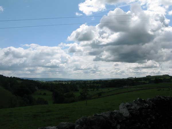
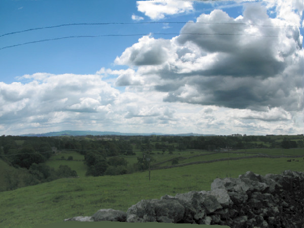
Source image, img_5143_sm.png.
The horizon is slightly below the mid-level.
There are two telegraph wires, almost straight lines,
with sky above them both.
|
|
|
For viewing the image,
the algQtr filter
(see
Adaptive auto level and gamma: Two-by-two blend)
shows more detail.
if "%IM32f%"=="" call %PICTBAT%setIm8

call %PICTBAT%algQtr ^
  img_5143_sm.png sh_algq.jpg
|
|
We will flatten the hills on the horizon.
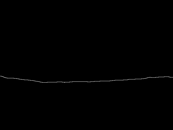
We define the line that we want to be straightened. By blurring, we follow the line of the landscape but ignore the detail of the trees.
|
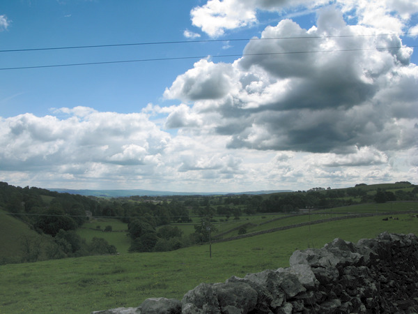
Source image, img_5143_sm.png.
%IM%convert ^
  img_5143_sm.png ^
  +write sh_horz_90.miff ^
  -blur 0x5 ^
  -threshold 25%% ^
  -format %%[fx:mean] +write info: ^
  -edge 1 ^
  +write sh_horz_line.png ^
  -rotate 90 ^
  sh_horz_line_90.miff
0.616619
The number gives the proportion of the image that is sky.
|
|
|
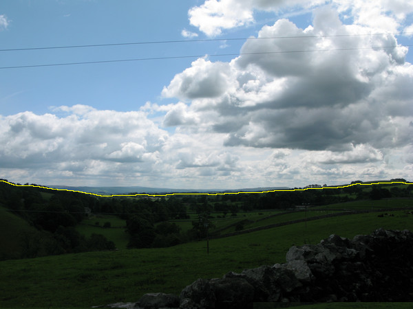
As a visual check, compose the horizon line over the source image.
%IM%convert ^
  img_5143_sm.png ^
  ( sh_horz_line.png ^
    -transparent Black ^
    -fill Yellow -opaque White ^
  ) ^
  -compose Over -composite ^
  sh_vis_chk.png
|
|
We can use the inverse of the follow-line process (see the
Follow line page) to straighten a horizon. The script
followLine.bat makes a displacement map to move the central vertical column to a defined line. The inverse will move a defined line to the central vertical column.
%IM%convert ^
  img_5143_sm.png ^
  -rotate 90 ^
  sh_horz_90.miff
Find the map that would displace the central vertical column to the horizon line.
call %PICTBAT%followLine ^
  sh_horz_90.miff sh_horz_line_90.miff NULL:
Invert the map.
%IMDEV%convert ^
  fl_disp_map_abs.miff ^
  -process invdispmap ^
  -channel R -evaluate Add 0%% +channel ^
  sh_inv_horz_disp.miff
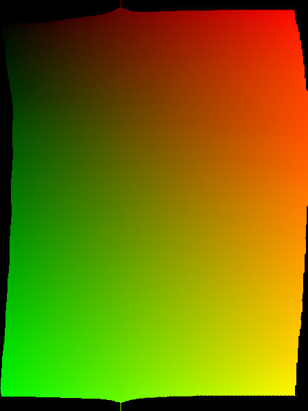
Fill the holes.
call %PICTBAT%blurFillSparse ^
  sh_inv_horz_disp.miff ^
  . ^
  sh_inv_horz_disp_bf.miff

%IM%convert ^
  sh_inv_horz_disp_bf.miff ^
  sh_inv_horz_disp_bf.png
|
|
|
Displace with the map.
set FORM=WW=%%w\n^
HH=%%h\n^
W_2=%%[fx:w/2]\n^
H_2=%%[fx:h/2]

for /F "usebackq" %%L in (`%IM%identify ^
  -format "%FORM%" ^
  sh_horz_90.miff`) do set %%L

%IM%convert ^
  sh_horz_90.miff ^
  sh_inv_horz_disp_bf.miff ^
  -compose Distort ^
    -set option:compose:args %W_2%x%H_2% ^
    -composite ^
  -rotate -90 ^
  sh_horz_dedisp_a.miff

call %PICTBAT%algQtr ^
  sh_horz_dedisp_a.miff sh_algq_a.png
|

|
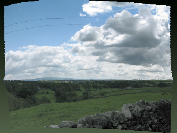
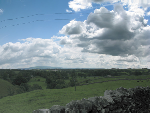
The output image is the same size as the input. The horizon has become straight, half way up the image. The telegraph lines have become curved. The bottom tenth (roughly) of the image has repeated pixels.
Because the image has moved up, we have lost the sky above the telegraph lines and pixels have repeated along the bottom edge. The absolute displacement map (before the inversion) shows why this happens, and what we can do about it.
set FORM=channel,min,mean,max\n^
red,%%[fx:minima.r],%%[fx:mean.r],%%[fx:maxima.r]\n^
green,%%[fx:minima.g],%%[fx:mean.g],%%[fx:maxima.g]

%IMDEV%convert ^
  fl_disp_map_abs.miff ^
  -format "%FORM%" ^
  info: >sh_abs_vals.csv

if ERRORLEVEL 1 goto error

call csv2tab sh_abs_vals
| channel |
min |
mean |
max |
| red |
0.499994 |
0.500002 |
0.50001 |
| green |
0 |
0.500818 |
0.998535 |
The red channel controls the horizontal displacement of the 90°-rotated image, hence the vertical displacement of the final image. The minimum, mean and maximum red values are all about 0.1 above the null-displacement values. We could subtract a fixed amount to reduce the values to approximately 0.0, 0.5 and 1.0. Or we can simply "-auto-level". We could do this for just one channel, or both. Auto-level will change the aspect ratio of the image; this could be fixed by a "-resize". It may also reduce the straightness of the diplaced horizon line; this isn't a problem in this image, as the horizon is close to the centre, and the min and max red are values nearly the same distance from 0.0 and 1.0, and we don't want the horizon to be exactly straight (we only want the smoothed horizon to be straight).
|
Auto-level and invert the map.
%IMDEV%convert ^
  fl_disp_map_abs.miff ^
  -channel RG -auto-level +channel ^
  -process invdispmap ^
  -channel R -evaluate Add 0%% +channel ^
  sh_inv_horz_disp2.miff
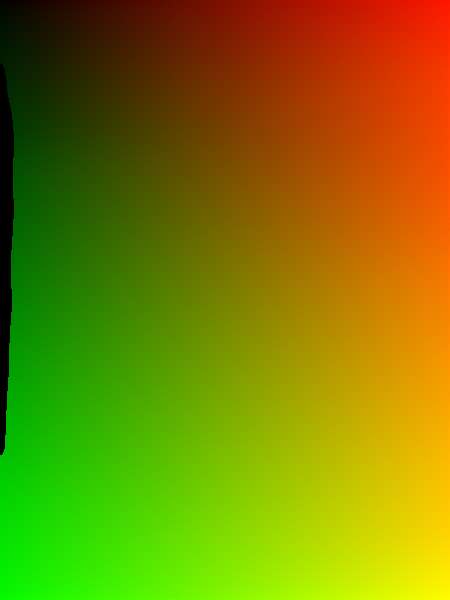
Fill the holes.
call %PICTBAT%blurFillSparse ^
  sh_inv_horz_disp2.miff ^
  . ^
  sh_inv_horz_disp_bf2.miff

%IM%convert ^
  sh_inv_horz_disp_bf2.miff ^
  sh_inv_horz_disp_bf2.png
|
|
|
Displace with the map.
%IM%convert ^
  sh_horz_90.miff ^
  sh_inv_horz_disp_bf2.miff ^
  -compose Distort ^
    -set option:compose:args %W_2%x%H_2% ^
    -composite ^
  -rotate -90 ^
  sh_horz_dedisp_a2.miff

call %PICTBAT%algQtr ^
  sh_horz_dedisp_a2.miff sh_algq_a2.png
|
|
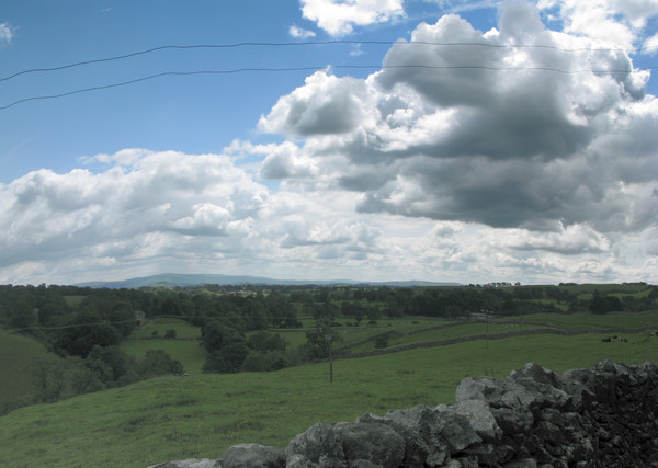
The "-auto-level" has ensured that at least one pixel on each edge is real, but the curved nature of the displacement has still given us repeated pixels. To eliminate repeated pixels, we want the absolute map to have values in the red channel of every row to extend to at least 0 to 100%, and the green channel of every column to also extend to at least 0 to 100%.
Assuming the values increase monotonically, we can find the maximum red value along the west edge and the minumum red value along the east edge, then "-level" the red channel between these values. Similarly for the green channel at the north and south edges. Like "-auto-level", this will change the aspect ratio, and may reduce the straightness of the displaced horizon line.
FIXME: but what about the holes? Blah.
for /F "usebackq" %%L in (`%IM%identify ^
  -format "WW=%%w\nHH=%%h\nWm1=%%[fx:w-1]\nHm1=%%[fx:h-1]" ^
  fl_disp_map_abs.miff`) do set %%L

for /F "usebackq" %%L in (`%IMDEV%convert ^
  fl_disp_map_abs.miff ^
  ^( -clone 0 ^
     -gravity West -crop 1x%HH%+0+0 ^
     -format "Rlo=%%[fx:100*maxima.r]\n" ^
     +write info: ^
     +delete ^
  ^) ^
  ^( -clone 0 ^
     -gravity East -crop 1x%HH%+0+0 ^
     -format "Rhi=%%[fx:100*minima.r]\n" ^
     +write info: ^
     +delete ^
  ^) ^
  ^( -clone 0 ^
     -gravity North -crop %WW%x1+0+0 ^
     -format "Glo=%%[fx:100*maxima.g]\n" ^
     +write info: ^
     +delete ^
  ^) ^
  ^( -clone 0 ^
     -gravity South -crop %WW%x1+0+0 ^
     -format "Ghi=%%[fx:100*minima.g]\n" ^
     +write info: ^
     +delete ^
  ^) ^
  NULL:`) do set %%L

echo Rlo=%Rlo% Rhi=%Rhi% Glo=%Glo% Ghi=%Ghi%
Rlo=49.9994 Rhi=50.0009 Glo=5.7251 Ghi=96.2402
%IMDEV%convert ^
  fl_disp_map_abs.miff ^
  -channel R -level %Rlo%%%,%Rhi%%% ^
  -channel G -level %Glo%%%,%Ghi%%% ^
  +channel ^
  -define quantum:format=floating-point ^
  fl_disp_map_abs_lev.miff
|
Invert the levelled map.
%IMDEV%convert ^
  fl_disp_map_abs_lev.miff ^
  -process invdispmap ^
  -channel R -evaluate Add 0%% +channel ^
  sh_inv_horz_disp3.miff
Fill the holes.
call %PICTBAT%blurFillSparse ^
  sh_inv_horz_disp3.miff ^
  . ^
  sh_inv_horz_disp_bf3.miff

%IM%convert ^
  sh_inv_horz_disp_bf3.miff ^
  sh_inv_horz_disp_bf3.png
|
|
|
Displace with the map.
%IM%convert ^
  sh_horz_90.miff ^
  sh_inv_horz_disp_bf3.miff ^
  -compose Distort ^
    -set option:compose:args %W_2%x%H_2% ^
    -composite ^
  -rotate -90 ^
  sh_horz_dedisp_a3.miff

call %PICTBAT%algQtr ^
  sh_horz_dedisp_a3.miff sh_algq_a3.png
|
|
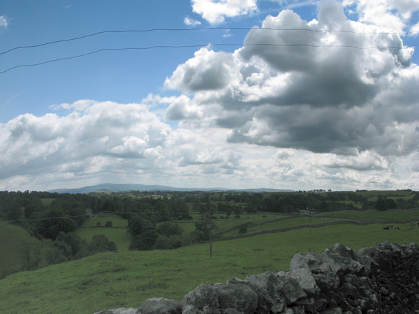
The result is good: the horizon is straight, at about the same vertical position as the input. Apart from the top row or two, and the right column or two, the pixels quite look good. There is clear aliasing in the telegraph wires and the distant horizon. This could be reduced by super-sampling.
Straightening the curved horizon has raised the centre of the horizon and lowered the two ends. It has also stretched out top-centre pixels horizontally, moving top-corner pixels out of the frame. Similarly, bottom-centre pixels have compressed.
Instead, we can straighten the horizon by shifting entire columns of pixels up or down.
This process is simpler and faster. It builds a relative displacement map where all the values in a column are equal.
We re-use sh_horz_line_90.miff, a white-line on black background, created above. We fill pixels beneath the line with white, and take the mean value. This gives us the mean height of the line, as a proportion of the height, from the bottom of the image.
We scale down to one row and up to the full height, adding (50% - mean) as we go. This gives us a relative displacement map, in the vertical direction only, with values slightly above and below 50%. The map would displace from a straight line to the wobbly curved horizon line, but we want to transform the horizon line to be straight, so we need to invert the map. Inverting a single-direction relative displacement map is simple: we negate it.
The displacement map will be scaled by IM to the image height, so it is important that it can record enough precision. Insufficient precision will create quantization, causing visible "stepping". Eight-bit files can record only 256 values, so are insufficient even for web images. For photographs of a few thousand pixels, integer Q16 may not have enough precision. See
How much precision? below.
set FORM=WW=%%w\n^
HH=%%h\n^
Wm1=%%[fx:w-1]\n^
Hm1=%%[fx:h-1]\n^
W_2=%%[fx:w/2]\n^
H_2=%%[fx:h/2]

for /F "usebackq" %%L in (`%IM%identify ^
  -format "%FORM%" ^
  img_5143_sm.png`) do set %%L

for /F "usebackq" %%L in (`%IMDEV%convert ^
  sh_horz_line.png ^
  -fill White ^
  -draw "color 0,%Hm1% floodfill" ^
  -format "MEAN=%%[fx:mean]\nADD_REL=%%[fx:100*(0.5-mean)]" ^
  +write info: ^
  -scale "%WW%x1^!"
  +depth ^
  sh_shcol.miff`) do set %%L

%IM%convert sh_shcol.miff sh_shcol.png

echo MEAN=%MEAN% ADD_REL=%ADD_REL%
MEAN=0.385796 ADD_REL=11.4204
If the mean is 39%,
then we need to add 50%-39% = 11%
to the relative displacement map.
|

|
|
Finish making the displacement map.
for /F "usebackq" %%L in (`%IMDEV%convert ^
  sh_shcol.miff ^
  -evaluate Add %ADD_REL%%% ^
  -negate ^
  -format "MIN_DY=%%[fx:minima]\nMAX_DY=%%[fx:maxima]"
  +write info: ^
  -scale "%WW%x%HH%^!" ^
  sh_shcol2.miff`) do set %%L

%IM%convert sh_shcol2.miff sh_shcol2.png

echo MIN_DY=%MIN_DY% MAX_DY=%MAX_DY%
MIN_DY=0.47024 MAX_DY=0.519129
|

|
|
Displace with this relative displacement map.
%IMDEV%convert ^
  img_5143_sm.png ^
  sh_shcol2.miff ^
  -compose Displace ^
    -set option:compose:args 0x%H_2% ^
    -composite ^
  sh_shcol_disp.miff

call %PICTBAT%algQtr ^
  sh_shcol_disp.miff sh_shcol_disp_algq.png
|

|
The telegraph lines and horizon have become aliased, because columns are shifted by integral numbers of pixels.
In this image, central columns have moved up, causing repeated pixels at bottom-centre. And columns at the right and left sides have moved down, causing repeated pixels at the top corners. The use of ADD_REL has guaranteed that MIN_DY <= 0.5 and 0.5 <= MAX_DY. MAX_DY occurs near the centre. The values of MIN_DY and MAX_DY tell us how much height we need to trim from top and bottom. (Trimming isn't shown here, but is implemented in the script.)
For convenience, we put this process into a script,
shiftCols.bat.
To reduce aliasing, we could super-sample the image. However, the source image is from a digital camera, so instead of supersampling, we will simply use the full-size image, repeating the entire process from scratch.
set SRC=%PICTLIB%20110727\IMG_5143.JPG

%IMDEV%convert ^
  %SRC% ^
  -blur 0x33 ^
  -threshold 25%% ^
  -edge 1 ^
  sh_horz_line_big.miff

call %PICTBAT%shiftCols ^
  %SRC% sh_horz_line_big.miff . sh_sc_big.miff

call %PICTBAT%algQtr ^
  sh_sc_big.miff sh_sc_big2.miff

%IM%convert ^
  sh_sc_big2.miff ^
  -resize 600x600 ^
  sh_big.png
|
|
As before, we have repeated pixels at bottom-centre and top corners. We can trim them off, or trim them and resize the image to stretch it back to its original size.
The source image is:
%IM%identify -format "%%wx%%h" %SRC%
4000x3000
|
Option 1: trim.
call %PICTBAT%shiftCols ^
  %SRC% sh_horz_line_big.miff 1 sh_sc_big_1.miff

%IM%identify -format "%%wx%%h" sh_sc_big_1.miff
4000x2848
call %PICTBAT%algQtr ^
  sh_sc_big_1.miff sh_sc_big2_1.miff

%IM%convert ^
  sh_sc_big2_1.miff ^
  -resize 600x600 ^
  sh_big_1.png
|
|
|
Option 2: trim and resize.
call %PICTBAT%shiftCols ^
  %SRC% sh_horz_line_big.miff 2 sh_sc_big_2.miff

%IM%identify -format "%%wx%%h" sh_sc_big_2.miff
4000x3000
call %PICTBAT%algQtr ^
  sh_sc_big_2.miff sh_sc_big2_2.miff

%IM%convert ^
  sh_sc_big2_2.miff ^
  -resize 600x600 ^
  sh_big_2.png
|
|
The human eye measures location with more precision than colour or lightness, where 8 bits is sufficient. It is more sensitive to changes in position than to changes in colour. The landscape photograph above has a height of 3000 pixels, so 8 bits is insufficiently precise to locate a height. 16 bits should be sufficient, but is it?
We can test this by running the
shiftCols.bat script under different varieties of IM. The results are cropped to a small length of telegraph wire, and scaled up so we can see them more clearly ("pixel peeping").
set LINE_FILE=sh_horz_line_big.miff
set PROC=-crop 100x30+1394+356 +repage -scale 400%%x400%%

set scIM=%IM8i%
call %PICTBAT%shiftCols %SRC% %LINE_FILE% . sh_temp.miff
%IM%convert sh_temp.miff %PROC% sh_prec_8i.png

set scIM=%IM8f%
call %PICTBAT%shiftCols %SRC% %LINE_FILE% . sh_temp.miff
%IM%convert sh_temp.miff %PROC% sh_prec_8f.png

set scIM=%IM16i%
call %PICTBAT%shiftCols %SRC% %LINE_FILE% . sh_temp.miff
%IM%convert sh_temp.miff %PROC% sh_prec_16i.png

set scIM=%IM16f%
call %PICTBAT%shiftCols %SRC% %LINE_FILE% . sh_temp.miff
%IM%convert sh_temp.miff %PROC% sh_prec_16f.png

set scIM=%IM32i%
call %PICTBAT%shiftCols %SRC% %LINE_FILE% . sh_temp.miff
%IM%convert sh_temp.miff %PROC% sh_prec_32i.png

set scIM=%IM32f%
call %PICTBAT%shiftCols %SRC% %LINE_FILE% . sh_temp.miff
%IM%convert sh_temp.miff %PROC% sh_prec_32f.png

set scIM=%IM64f%
call %PICTBAT%shiftCols %SRC% %LINE_FILE% . sh_temp.miff
%IM%convert sh_temp.miff %PROC% sh_prec_64f.png

set scIM=
Q32 and Q64, whether integer or HDRI, give the same results: the telegraph line has steps of a single pixel.
Q16, whether integer or HDRI, gives a worse result: the telegraph line has steps of two pixels.
Q8 HDRI is similarly bad, with steps of two pixels. Q8 integer is awful, with a jump of 12 pixels. Q8 also shows a vertical displacement, compared to the other versions.
Conclusion: for images of a few thousand pixels in each dimension, displacement maps should be created and used with Q32 or better.
A more numerical method of measuring accuracy of results is to note that if we shift the columns of the line file, using the exact same image as the line to be straightened, we should end up with a straight line, with one row of white pixels and black elsewhere. If we add a black border and trim, the height should be one.
echo ,integer,HDRI >sh_prec_r.csv

set scIM=%IM8i%
call %PICTBAT%shiftCols %LINE_FILE% %LINE_FILE% . sh_temp.miff
%scIM%convert sh_temp.miff -bordercolor Black -border 1 -trim -format "Q8,%%h," info: >>sh_prec_r.csv

set scIM=%IM8f%
call %PICTBAT%shiftCols %LINE_FILE% %LINE_FILE% . sh_temp.miff
%scIM%convert sh_temp.miff -bordercolor Black -border 1 -trim -format "%%h\n" info: >>sh_prec_r.csv

set scIM=%IM16i%
call %PICTBAT%shiftCols %LINE_FILE% %LINE_FILE% . sh_temp.miff
%scIM%convert sh_temp.miff -bordercolor Black -border 1 -trim -format "Q16,%%h," info: >>sh_prec_r.csv

set scIM=%IM16f%
call %PICTBAT%shiftCols %LINE_FILE% %LINE_FILE% . sh_temp.miff
%scIM%convert sh_temp.miff -bordercolor Black -border 1 -trim -format "%%h\n" info: >>sh_prec_r.csv

set scIM=%IM32i%
call %PICTBAT%shiftCols %LINE_FILE% %LINE_FILE% . sh_temp.miff
%scIM%convert sh_temp.miff -bordercolor Black -border 1 -trim -format "Q32,%%h," info: >>sh_prec_r.csv

set scIM=%IM32f%
call %PICTBAT%shiftCols %LINE_FILE% %LINE_FILE% . sh_temp.miff
%scIM%convert sh_temp.miff -bordercolor Black -border 1 -trim -format "%%h\n" info: >>sh_prec_r.csv

set scIM=%IM64f%
call %PICTBAT%shiftCols %LINE_FILE% %LINE_FILE% . sh_temp.miff
%scIM%convert sh_temp.miff -bordercolor Black -border 1 -trim -format "Q64,not available,%%h\n" info: >>sh_prec_r.csv

call csv2tab sh_prec_r
set scIM=
|
|
integer |
HDRI |
| Q8 |
15 |
5 |
| Q16 |
4 |
4 |
| Q32 |
3 |
3 |
| Q64 |
not available |
3 |
The white horizon line on black background is not aliased, so it wobbles in discrete steps of integer pixels. As a result, the displacement map also also varies in discrete steps of integer pixels, and the resulting image is always stepped, even with high-precision IM.
To reduce this effect, we can apply a small blur to the displacement map, by setting the environment variable scBLR_SIG.
set scBLR_SIG=4

set LINE_FILE=sh_horz_line_big.miff
set PROC=-crop 100x30+1394+356 +repage -scale 400%%x400%%

set scIM=%IM8i%
call %PICTBAT%shiftCols %SRC% %LINE_FILE% . sh_temp.miff
%IM%convert sh_temp.miff %PROC% sh_prec_b_8i.png

set scIM=%IM8f%
call %PICTBAT%shiftCols %SRC% %LINE_FILE% . sh_temp.miff
%IM%convert sh_temp.miff %PROC% sh_prec_b_8f.png

set scIM=%IM16i%
call %PICTBAT%shiftCols %SRC% %LINE_FILE% . sh_temp.miff
%IM%convert sh_temp.miff %PROC% sh_prec_b_16i.png

set scIM=%IM16f%
call %PICTBAT%shiftCols %SRC% %LINE_FILE% . sh_temp.miff
%IM%convert sh_temp.miff %PROC% sh_prec_b_16f.png

set scIM=%IM32i%
call %PICTBAT%shiftCols %SRC% %LINE_FILE% . sh_temp.miff
%IM%convert sh_temp.miff %PROC% sh_prec_b_32i.png

set scIM=%IM32f%
call %PICTBAT%shiftCols %SRC% %LINE_FILE% . sh_temp.miff
%IM%convert sh_temp.miff %PROC% sh_prec_b_32f.png

set scIM=%IM64f%
call %PICTBAT%shiftCols %SRC% %LINE_FILE% . sh_temp.miff
%IM%convert sh_temp.miff %PROC% sh_prec_b_64f.png

set scIM=
set scBLR_SIG=
This has little effect on the Q8 or Q16 versions. The Q32 and Q64 versions are greatly improved. Like any blurring, this reduces high-frequency components. If the blur radius scBLR_SIG is too high, it will smooth out peaks and troughs, reducing the effect of the displacement. The lowest useful radius is 2; a value of 4 seems sufficient to subjectively remove the aliasing effect.
Blurring the displacement is a kludge, to reduce the harmful effect of an aliased line file. We can do better.
Above, the line file was made with a threshold at 25%. Instead, we can "-level" between, say, 20% and 30%. The line file sh_line_aa.miff isn't just a line, but a white area at the bottom, a black are at the top, and a thin gradient between them. Hence there is no need for the shiftCols script to flood-fill with white. Setting the environment variable scFLOOD_WHITE to 0 prevents the filling.
%IM%convert ^
  %SRC% ^
  -colorspace Gray -blur 0x33 ^
  -level 20%%,30%% ^
  -negate ^
  sh_line_aa.miff

set scFLOOD_WHITE=0
set LINE_FILE=sh_line_aa.miff
set PROC=-crop 100x30+1394+356 +repage -scale 400%%x400%%

set scIM=%IM8i%
call %PICTBAT%shiftCols %SRC% %LINE_FILE% . sh_temp.miff
%IM%convert sh_temp.miff %PROC% sh_prec_aa_8i.png

set scIM=%IM8f%
call %PICTBAT%shiftCols %SRC% %LINE_FILE% . sh_temp.miff
%IM%convert sh_temp.miff %PROC% sh_prec_aa_8f.png

set scIM=%IM16i%
call %PICTBAT%shiftCols %SRC% %LINE_FILE% . sh_temp.miff
%IM%convert sh_temp.miff %PROC% sh_prec_aa_16i.png

set scIM=%IM16f%
call %PICTBAT%shiftCols %SRC% %LINE_FILE% . sh_temp.miff
%IM%convert sh_temp.miff %PROC% sh_prec_aa_16f.png

set scIM=%IM32i%
call %PICTBAT%shiftCols %SRC% %LINE_FILE% . sh_temp.miff
%IM%convert sh_temp.miff %PROC% sh_prec_aa_32i.png

set scIM=%IM32f%
call %PICTBAT%shiftCols %SRC% %LINE_FILE% . sh_temp.miff
%IM%convert sh_temp.miff %PROC% sh_prec_aa_32f.png

set scIM=%IM64f%
call %PICTBAT%shiftCols %SRC% %LINE_FILE% . sh_temp.miff
%IM%convert sh_temp.miff %PROC% sh_prec_aa_64f.png

set scIM=
set scFLOOD_WHITE=
Again, the effect on Q8 and Q16 is slight, but Q32 and Q64 show a significant improvement.
A blink-comparison between the blurred-map versions and these versions from the improved line file shows the latter are more smooth. There is also no danger of smoothing away the peaks and troughs of displacements. As a rule, it is better to start from good inputs than to compensate with kludges.
An alternative method for straightening the horizon, or giving it any arbitrary distortion, would be to use
"-distort Triangulate".
That method is not explored here.
We don't need to keep all those miff files, so delete them.
rem del sh_*.miff
For convenience, .bat scripts are also available in a single zip file. See
Zipped BAT files.
set QUANT_FP=

if /I "%~x1"==".miff" set QUANT_FP=-depth 32 +depth -define quantum:format^^^=floating-point

rem echo QUANT_FP=%QUANT_FP%
@rem From image %1 with transparency,
@rem blurs until fully opaque.
@rem
@rem Optional:
@rem   %2 blur sigma (default 1)
@rem     %2 can have a "+" suffix.
@rem     If it has, the sigma will increment on each pass.
@rem   %3 output filename
@rem   %4 blur type
@rem     0 -blur 0x{sigma}
@rem     1 -motion-blur 0x{sigma}+{angle}
@rem     2 -radial-blur {angle}
@rem   %5 angle
@rem
@rem  bfTHRESH_PC percentage of alpha for thresholding.
@rem    For thin lines, use a low value eg 3.
@rem  bfMAX_ITER maximum number of iterations. [Default max(w,h).]
@rem  bfMAX_SIG Stop when + results in sigma greater than this.
@rem   [Default no check.]
@rem
@rem  An equivalent compiled program wouldn't need to save images
@rem    between iterations, so would be faster.
@rem
@rem  Updated:
@rem    28-August-2018 Added bfMAX_SIG

@if "%1"=="" findstr /B "rem @rem" %~f0 & exit /B 1

@setlocal

rem @call echoOffSave

call %PICTBAT%setInOut %1 bf


set IN_BLR_SIG=%2
if "%IN_BLR_SIG%"=="." set IN_BLR_SIG=
if "%IN_BLR_SIG%"=="" set IN_BLR_SIG=1

rem echo IN_BLR_SIG=%IN_BLR_SIG%

set BLR_SUFFIX=%IN_BLR_SIG:~-1%
if "%BLR_SUFFIX%"=="+" (
  set BLR_SIG=%IN_BLR_SIG:~0,-1%
) else (
  set BLR_SUFFIX=
  set BLR_SIG=%IN_BLR_SIG%
)

if not "%3"=="" if not "%3"=="." set OUTFILE=%3

echo %~n0: INFILE=%INFILE% OUTFILE=%OUTFILE% BLR_SIG=%BLR_SIG% BLR_SUFFIX=%BLR_SUFFIX%  OUT_NUM=%OUT_NUM%

set BLR_TYPE=%4
if "%BLR_TYPE%"=="." set BLR_TYPE=
if "%BLR_TYPE%"=="" set BLR_TYPE=0

set BLR_ANG=%5
if "%BLR_ANG%"=="." set BLR_ANG=
if "%BLR_ANG%"=="" set BLR_ANG=0

if %BLR_TYPE%==0 (
  set sBLUR=-blur 0x%BLR_SIG%
) else if %BLR_TYPE%==1 (
  set sBLUR=-channel RGBA -motion-blur 0x%BLR_SIG%+%BLR_ANG% +channel
) else if %BLR_TYPE%==2 (
  set sBLUR=-channel RGBA -radial-blur %BLR_ANG% +channel
) else (
  echo %0: Unknown BLR_TYPE=%BLR_TYPE%
  exit /B 1
)

if "%bfMAX_SIG%"=="" set bfMAX_SIG=1e9
set SIG_OK=1

echo %0: sBLUR=%sBLUR%

call %PICTBAT%quantFp %OUTFILE%

if "%bfTHRESH_PC%"=="" set bfTHRESH_PC=25

if "%bfMAX_ITER%"=="" for /F "usebackq" %%L in (`%IM%identify ^
  -format "bfMAX_ITER=%%[fx:max(w,h)]" ^
  %INFILE%`) do set %%L
if "%bfMAX_ITER%"=="" exit /B 1

rem echo bfMAX_ITER=%bfMAX_ITER%

if "%IM32f%"=="" call %PICTBAT%setIm8

set TMPDIR=\temp
set TMP_INFILE=%TMPDIR%\bf_tmpin.miff
set TMP_FILE=%TMPDIR%\bf1.miff

%IM%convert ^
  %INFILE% ^
  +write %TMP_INFILE% ^
  -channel A ^
  -threshold %bfTHRESH_PC%%% ^
  +channel ^
  %TMP_FILE%
if ERRORLEVEL 1 exit /B 1

set nITER=0
set MEAN=-1

:loop
set PREV_MEAN=%MEAN%

set MIN=

for /F "usebackq" %%L in (`%IM%convert ^
  %TMP_FILE% ^
  ^( +clone ^
     -alpha extract ^
     +write mpr:ALP ^
     +delete ^
  ^) ^
  %sBLUR% ^
  ^( +clone ^
     -alpha extract ^
     mpr:ALP ^
     -compose Lighten -composite ^
     -threshold %bfTHRESH_PC%%% ^
     -precision 15 ^
     -format "MIN=%%[fx:minima]\nMAX=%%[fx:maxima]\nMEAN=%%[fx:mean]\n" +write info: ^
  ^) ^
  -alpha off -compose CopyOpacity -composite ^
  %TMP_INFILE% ^
  -compose Over -composite ^
  -channel RGBA -clamp +channel ^
  +depth ^
  %QUANT_FP% ^
  %TMP_FILE%`) do set %%L

if "%MIN%"=="" (
  echo %0: convert failed
  exit /B 1
)

if "%BLR_SUFFIX%"=="+" (
  for /F "usebackq" %%L in (`%IM%identify ^
  -format "BLR_SIG=%%[fx:%BLR_SIG%*1.01]\nSIG_OK=%%[fx:%BLR_SIG%>%bfMAX_SIG%?0:1]" ^
  xc:`) do set %%L

  if %BLR_TYPE%==0 (
    set sBLUR=-blur 0x%BLR_SIG%
  ) else if %BLR_TYPE%==1 (
    set sBLUR=-motion-blur 0x%BLR_SIG%+%BLR_ANG%
  )
)

set /A nITER+=1

echo %~n0: nITER=%nITER% MIN=%MIN% MAX=%MAX% MEAN=%MEAN% BLR_SIG=%BLR_SIG% SIG_OK=%SIG_OK%

if %nITER% LSS %bfMAX_ITER% if "%PREV_MEAN%" NEQ "%MEAN%" if %SIG_OK%==1 goto loop
rem if "%MIN%"=="0" goto loop

rem if not "%MIN%"=="1"

echo %~n0: bfMAX_ITER=%bfMAX_ITER% nITER=%nITER%

%IM%convert ^
  %TMP_FILE% ^
  %QUANT_FP% ^
  %OUTFILE%

rem  %QUANT_FP%

if not "%MEAN%"=="1" (
  set BUST=1
) else (
  set BUST=0
)

call echoRestore

@endlocal & set bfOUTFILE=%OUTFILE%& set bfBUST=%BUST%
rem Given image %1
rem and %2, same size, a narrow white line on black background across the full width,
rem makes version of %1 with columns shifted so line becomes straight,
rem at same average height as it was.
rem %3 is optional treatment of repeated pixels:
rem   0 leave them in the image (so image remains the same size).
rem   1 trim them away (so image will have reduced height).
rem   2 trim, then resize to original size (changing aspect ratio).
rem %4 is optional output file.
@rem
@rem Also uses:
@rem   scBLR_SIG radius of blur to be applied to the map. Default 0 = no blur.
@rem   scFLOOD_WHITE 0=don't flood; 1=do flood. Default 1.
@rem
@rem Assumes bottom-left pixel in %2 is in "lower" half.

@if "%2"=="" findstr /B "rem @rem" %~f0 & exit /B 1

@setlocal

@call echoOffSave

call %PICTBAT%setInOut %1 sc

set LINE_FILE=%2

set TREAT_REP=%3
if "%TREAT_REP%"=="." set TREAT_REP=
if "%TREAT_REP%"=="" set TREAT_REP=0

if not "%4"=="" set OUTFILE=%4

if "%IM32f%"=="" call %PICTBAT%setIm8

if "%scIM%"=="" set scIM=%IM32f%

if "%scBLR_SIG%"=="" set scBLR_SIG=0
if "%scBLR_SIG%"=="0" (
  set sBLUR=
) else (
  set sBLUR=-blur 0x%scBLR_SIG%
)

echo sBLUR=%sBLUR%

if "%scFLOOD_WHITE%"=="" set scFLOOD_WHITE=1

set TMP1=\temp\%~n1_sc.miff
set TMP2=\temp\%~n1_sc2.miff

set FORM=WW=%%w\n^
HH=%%h\n^
Wm1=%%[fx:w-1]\n^
Hm1=%%[fx:h-1]\n^
W_2=%%[fx:w/2]\n^
H_2=%%[fx:h/2]

for /F "usebackq" %%L in (`%IM%identify ^
  -format "%FORM%" ^
  %LINE_FILE%`) do set %%L

if "%scFLOOD_WHITE%"=="1" (
  set sFLOOD=-fill Red ^
-draw "color 0,%Hm1% floodfill" ^
-fill Gray^^^(50%%^^^) -opaque White ^
-fill White -opaque Red
) else (
  set sFLOOD=
)

echo sFLOOD=%sFLOOD%

call %PICTBAT%quantFp %TMP1%

for /F "usebackq" %%L in (`%scIM%convert ^
  %LINE_FILE% ^
  %sFLOOD% ^
  -format "ADD_REL=%%[fx:100*(0.5-mean)]" ^
  +write info: ^
  -scale "%WW%x1^!" ^
  %sBLUR% ^
  +depth ^
  %QUANT_FP% ^
  "%TMP1%"`) do set %%L

echo ADD_REL=%ADD_REL%

for /F "usebackq" %%L in (`%scIM%convert ^
  "%TMP1%" ^
  -evaluate Add %ADD_REL%%% ^
  -negate ^
  -format "MIN_DY=%%[fx:minima]\nMAX_DY=%%[fx:maxima]"
  +write info: ^
  -scale "%WW%x%HH%^!" ^
  %QUANT_FP% ^
  "%TMP2%"`) do set %%L

echo MIN_DY=%MIN_DY% MAX_DY=%MAX_DY%

if %TREAT_REP% GTR 0 (
  for /F "usebackq" %%L in (`%scIM%identify ^
    -format "TRIM_TOP=%%[fx:int((0.5-%MIN_DY%)*%HH%+0.5)]\nTRIM_BOT=%%[fx:int((%MAX_DY%-0.5)*%HH%+0.5)]" ^
    xc:`) do set %%L

  set /A NEW_HT=%HH%-!TRIM_TOP!-!TRIM_BOT!

  set sCROP=-crop %WW%x!NEW_HT!+0+!TRIM_TOP! +repage
) else (
  set sCROP=
)

if %TREAT_REP% EQU 2 (
  set sRESIZE=-resize "%WW%x%HH%^^^!"
) else (
  set sRESIZE=
)

call %PICTBAT%quantFp %OUTFILE%

%scIM%convert ^
  %INFILE% ^
  "%TMP2%" ^
  -compose Displace ^
    -set option:compose:args 0x%H_2% ^
    -composite ^
  %sCROP% ^
  %sRESIZE% ^
  %QUANT_FP% ^
  %OUTFILE%


call echoRestore

endlocal & set scOUTFILE=%OUTFILE%
This takes a comma-separated values (CSV) file and builds a file with HTML table syntax. It uses my own programs such as chSep.exe. I don't publish the source or executables of these.
rem From %1.csv, creates partial %1.htm with a table.
rem %2 is parameters to table, eg "border".

set c2tTAB_PARAMS=%2
if "%c2tTAB_PARAMS%"=="." set c2tTAB_PARAMS=

chSep   /p0 /i%1.csv /o%1.htm /f"," /t\(/td\)\(td\) /T\(/th\)\(th\) /n
cPrefix /p0 /i%1.htm /l\(tr\)\(td\) /r\(/td\)\(/tr\) /t"\(table %c2tTAB_PARAMS%\)" /b\(/table\) /X
chStrs  /p0 /i%1.htm /m1 /f\(td\) /t\(th\)
chStrs  /p0 /i%1.htm /m1 /f\(/td\) /t\(/th\)
All images on this page were created by the commands shown, using:
%IM%identify -version
Version: ImageMagick 6.9.9-50 Q16 x64 2018-06-02 http://www.imagemagick.org
Copyright: Copyright (C) 1999-2015 ImageMagick Studio LLC
License: http://www.imagemagick.org/script/license.php
Visual C++: 180040629
Features: Cipher DPC Modules OpenMP
Delegates (built-in): bzlib cairo flif freetype gslib heic jng jp2 jpeg lcms lqr lzma openexr pangocairo png ps raw rsvg tiff webp xml zlib
The customised development version is:
%IMDEV%identify -version
Version: ImageMagick 6.9.9-40 Q32 x86_64 2018-12-09 http://www.imagemagick.org
Copyright: © 1999-2018 ImageMagick Studio LLC
License: http://www.imagemagick.org/script/license.php
Features: Cipher DPC HDRI Modules OpenMP
Delegates (built-in): bzlib cairo fftw fontconfig fpx freetype jbig jng jpeg lcms ltdl lzma pangocairo png rsvg tiff webp wmf x xml zlib
To improve internet download speeds, some images may have been automatically converted (by ImageMagick, of course) from PNG to JPG.
Source file for this web page is strhoriz.h1. To re-create this web page, run "procH1 strhoriz".
This page, including the images, is my copyright. Anyone is permitted to use or adapt any of the code, scripts or images for any purpose, including commercial use.
Anyone is permitted to re-publish this page, but only for non-commercial use.
Anyone is permitted to link to this page, including for commercial use.
Page version v1.0 21-July-2015.
Page created 07-Jun-2019 21:47:18.
Copyright © 2019 Alan Gibson.