curvelines.png
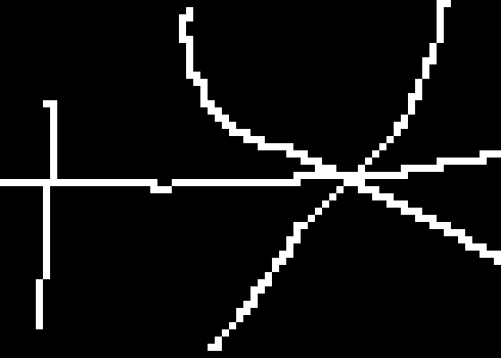
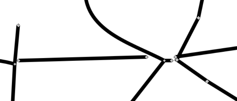
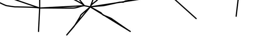
Here is an enlargement
of the bottom-center:
%IMG7%magick ^
  curvelines.png ^
  -crop 70x50+260+340 ^
  +repage ^
  -scale 800%% ^
  lpc_crp.png
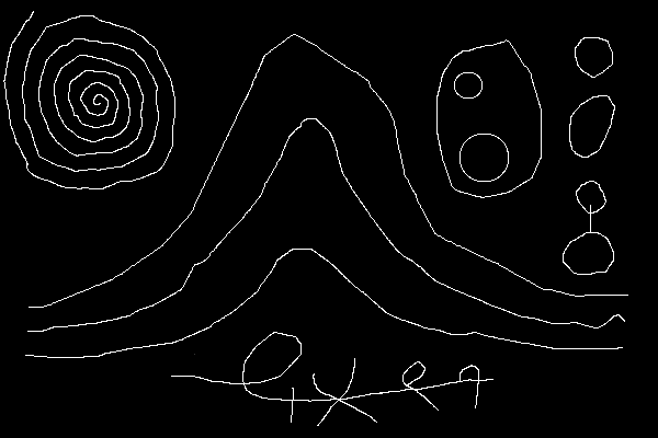
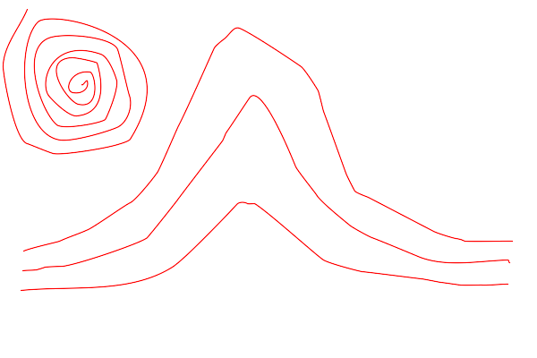
Wobbly raster lines can be expressed as ordered sets of coordinates, and simplified to vectors.
For a certain job, I needed to vectorize raster lines. That is, for lines defined as connected pixels, I needed to create SVG Bézier curves. I couldn't find an open source package to do this.
We divide the problem into two sub-problems:
Sub-problem (2) is quite easy; see pts2bez.exe in From points to curves below. Sub-problem (1) is more difficult, and is the main subject of this page.
To illustrate issues in sub-problem (1), we use pts2bez.exe.
The first step towards vectorization of a line is to list the coordinates of the line in the correct order, from one end to the other, as if the line were being drawn by a pen or cut with a knife, router or laser. This is fairly simple when lines don't cross, and there are no loops.
Scripts on this page assume that the version of ImageMagick in %IM7DEV% has been built with various process modules. See Process modules.
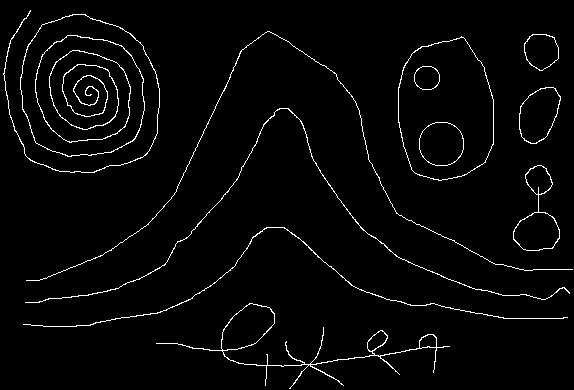
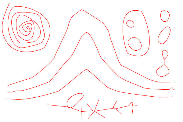
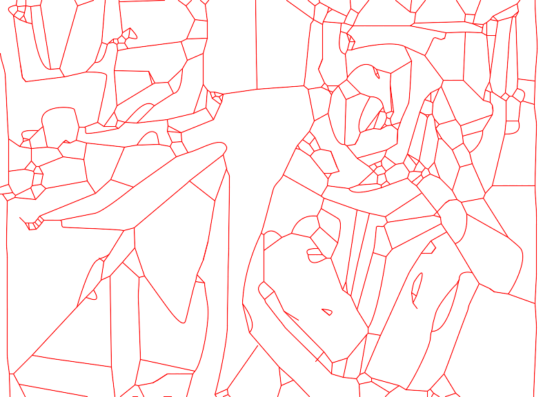
We make a doodle with Gimp, a number of white lines on a black background.
|
curvelines.png |
|
|
Here is an enlargement
%IMG7%magick ^ curvelines.png ^ -crop 70x50+260+340 ^ +repage ^ -scale 800%% ^ lpc_crp.png |
|
Potrace is very good at creating a closed curve at a black/white boundary. Inkscape extends this, finding closed curves of solid colours. Potrace will vectorize both sides of a line, so we could extract from the result just one half. This would work for simple lines (without junctions or loops). For complex lines, extracting the appropriate data from potrace's output would be messy.
Potrace successfully and quickly vectorizes the image.
%IMG7%magick curvelines.png lpc_c.pgm

potrace -s -o lpc_po.svg lpc_c.pgm
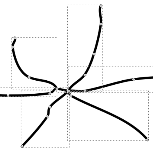
However, it vectorizes the boundary between the black and white pixels, A line has a boundary along both sides. If we view the SVG in Inkscape, zoomed in ...
... we see there are control points on both sides of the line. This isn't what I wanted. I couldn't see a simple way of adapting the potrace library to do what I wanted, so I started from scratch.
ASIDE:
Listing the coordinates around the boundary of a closed curve, tracing a contour, is a simpler problem because contours cannot cross each other or themselves. See Wikipedia: Moore neighborhood.
We can replicate this contour tracing in a fairly simple script, traceContour.bat, which lists boundary coordinates of a white shape in clockwise order (that is, the white pixels will be on the right side of the resulting line). Result coordinates are integers, possibly plus or minus 0.5.
It runs magick multiple times for every pixel, so is massively slow. It could be coded as a process module, but without much point, as potrace does a good job of this task.
The script follows the algorithm shown in Wikipedia fairly closely, but it would probably be quicker to read a block of nine pixels and maniplate those to find the next clockwise white pixel.
The script traces just one continuous boundary. The image crosscurves.png contains four distinct boundaries: the main one, and the insides of three closed curves.
|
crosscurves.png |
|
call %PICTBAT%traceContour crosscurves.png lpc_tc.txt
We can vectorize those coordinates into Bézier curves, and rasterize the curves:
pts2bez ^ /ilpc_tc.txt /olpc_tc_b.txt /M2 /e1 %IMG7%magick ^ -size 600x200 xc:White ^ -fill None ^ -draw @lpc_tc_b.txt ^ lpc_tc_b.png |
|
|
Relax the error tolerance. pts2bez ^ /ilpc_tc.txt /olpc_tc_b2.txt /M2 /e2 %IMG7%magick ^ -size 600x200 xc:White ^ -fill None ^ -draw @lpc_tc_b2.txt ^ lpc_tc_b2.png |
|
|
Relax the error tolerance further. pts2bez ^ /ilpc_tc.txt /olpc_tc_b3.txt /M2 /e5 %IMG7%magick ^ -size 600x200 xc:White ^ -fill None ^ -draw @lpc_tc_b3.txt ^ lpc_tc_b3.png |
|
|
Relax the error tolerance further. pts2bez ^ /ilpc_tc.txt /olpc_tc_b4.txt /M2 /e10 %IMG7%magick ^ -size 600x200 xc:White ^ -fill None ^ -draw @lpc_tc_b4.txt ^ lpc_tc_b4.png |
|
With the relaxed error tolerance, we clearly see the boundary of the figure has been vectorized.
But this is a side-issue. I don't want to vectorize boundaries, but lines. We return to the main topic.
See the AutoTrace website.
Another popular raster-to-vector program is AutoTrace. By default, this traces outlines (like potrace). But it has a -centerline option, which gives this SVG, when enlarged in Inkscape:
AutoTrace has vectorized the centres of the lines. However, it has disconnected line segments so they no longer meet at junctions. Perhaps some combination of its numerous options would fix the problem, but the documentation is sparse. It seems AutoTrace is no longer maintained. It makes calls to ImageMagick that are not valid with recent versions of IM.

Provided a line has exactly two ends, tracing it is fairly simple. We choose one of the ends as the start, negate and add one so the pixels on the path are just above black and those off the path are white, then visit the pixels that are below 50% with Dijkstra's algorithm, as implemented in the darkestpntpnt process module.
The script traceLn.bat traces the points in the line starting at the given coordinate, which should be one end. It appends the coordinates to a text file, so we might want to ensure the file doesn't already exist.
If we happen to know that the spiral in the top-left has one end at (30,10), we can list the coordinates of all its pixels:
del lpc_ln1.txt

call %PICTBAT%traceLn curvelines.png 30 10 lpc_ln1.txt

echo tlNumPts=%tlNumPts% tlLastX=%tlLastX% tlLastY=%tlLastY%
tlNumPts=1828 tlLastX=91 tlLastY=94
The spiral at the top-left has 1828 pixels. It finishes at coordinate (91,94).
The first and last five lines of lpc_ln1.txt are:
30,10
30,11
29,11
29,12
29,13
:
:
88,95
89,95
90,95
90,94
91,94
This works for any thickness of line; all the white pixels will be traced.
(Tracing the coordinates of a line could be done with Morphology constrained distance, using a write-protect mask. This (very slowly) gives a gradient along the line, so we could extract these coordinates and intensity, then sort by intensity.)
The script lns2pts.bat processes multiple lines that are all simple. That is, lines that do not cross each other or loop.
The input image file should be a number of connected components, where each component is a white line with two ends, 8-connected or 4-connected. The output text file will be a list of the pixels, separated into lines. It starts at the nearest line-end to 0,0. After tracing a line, it starts the next at the nearest line-end.
|
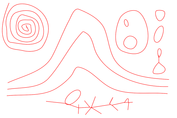
Make an image with Gimp: fourcurves.png |
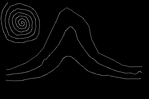
|
From a image of white lines on a black background, the script creates a text file of coordinates in the lines.
call %PICTBAT%lns2pts ^
  fourcurves.png lpc_4c.txt
The first and last five lines of the created text file lpc_4c.txt are:
numLines=4
line
numPts=1828
30,10
29,11
:
:
563,318
564,317
565,317
566,317
567,317
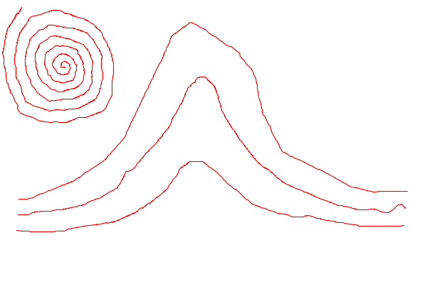
We can vectorize those coordinates into Bézier curves:
pts2bez /ilpc_4c.txt /olpc_4cb.txt
The first and last five lines of the created text file lpc_4cb.txt are:
stroke red bezier 30.00,10.00 29.55,11.12 28.45,11.88 28.00,13.00
stroke red bezier 28.00,13.00 27.88,13.31 29.12,12.69 29.00,13.00
stroke red bezier 29.00,13.00 28.65,13.88 27.35,14.12 27.00,15.00
stroke red bezier 27.00,15.00 26.88,15.31 28.15,14.70 28.00,15.00
stroke red bezier 28.00,15.00 27.88,15.24 25.46,17.32 25.00,18.00
:
:
stroke red bezier 539.00,318.00 540.70,317.97 547.46,318.01 548.00,318.00
stroke red bezier 548.00,318.00 548.60,317.99 550.80,318.00 551.00,318.00
stroke red bezier 551.00,318.00 552.63,317.97 558.70,318.00 559.00,318.00
stroke red bezier 559.00,318.00 559.60,317.99 561.80,318.00 562.00,318.00
stroke red bezier 562.00,318.00 562.56,317.99 565.05,317.03 567.00,317.00
Now we rasterize the Bézier curves:
%IMG7%magick ^ -size 600x400 xc:White ^ -fill None ^ -draw @lpc_4cb.txt ^ lpc_4cb.png |
|
|
Draw the curve over the input, to see how close it is. %IMG7%magick ^ fourcurves.png ^ -fill None ^ -draw @lpc_4cb.txt ^ lpc_4cbi.png |
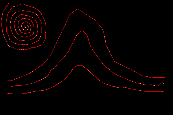
|
|
A larger error tolerance. pts2bez ^ /ilpc_4c.txt /olpc_4cb2.txt /e10 if ERRORLEVEL 1 goto error %IMG7%magick ^ -size 600x400 xc:White ^ -fill None ^ -draw @lpc_4cb2.txt ^ lpc_4cb2.png |
|
|
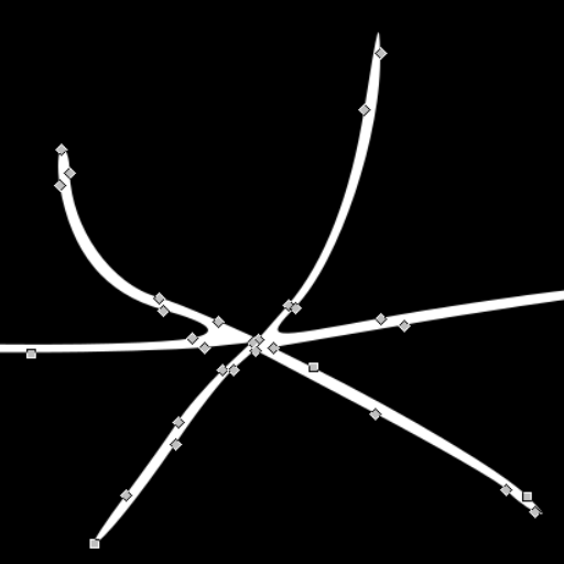
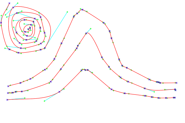
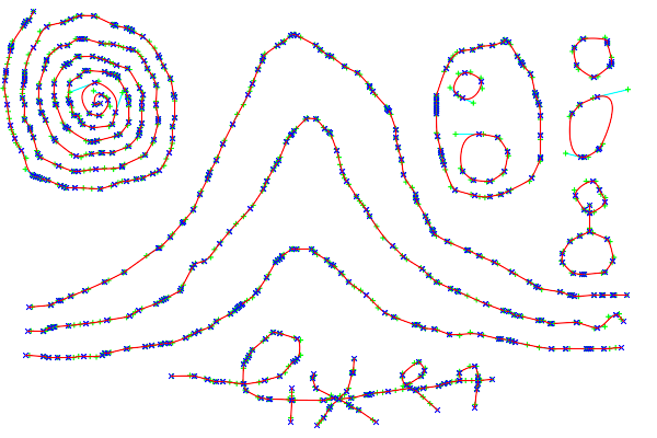
As previous, but showing points and tangents. pts2bez ^ /ilpc_4c.txt /olpc_4cb3.txt /e10 /p7 if ERRORLEVEL 1 goto error %IMG7%magick ^ -size 600x400 xc:White ^ -fill None ^ -draw @lpc_4cb3.txt ^ lpc_4cb3.png |
|
The program pts2bez.exe draws tangents, control points, knots, and Bézier curves are in cyan, lime, blue and red respectively.
If all lines had exactly two ends, the job would be done. But junctions and loops make the job more complex.

Multiple lines can cross or meet at junctions. When they cross like "+" or "X", we would like to recognise the arms of the cross that correspond. If we draw a line inwards from the left arm of a "+", we want the next action to draw outwards along the right arm.
With IM, we can easily and quickly identify pixels that form junctions, remove them from the main image and store them in another image, then find all the line ends. (We include each isolated white pixel as a "junction".) When we trace the line, we test the first and last pixels for being adjacent to a junction.
Why do we treat each isolated white pixel as a "junction"? They often occur as a result of staggered junctions, which morphology would regard as two distinct junctions joined by a line of length one. This is difficult to process, to ensure the line exits from one junction but enters the other, rather that re-entering the junction it came from. So, instead of doing this, we simply join the junctions together.
This does mean that if the input image has any isolated white pixels, they will not be converted to curves.
I might modify the script so that an isolated white pixel at (x,y) becomes the sequence "M x,y L x,y".
When a line is a closed curve with no junctions, a topological circle, so it joins itself, we can pick any arbitrary point as the start, and visit the pixels in either direction until we revisit the start.
IM doesn't have a simple test for loops. By flood-filling from the line ends, we remove all simple lines. We have already removed junctions. Any remaining white pixels must be in loops. This is stored as image LOOPS.
When we have just loops (so there are no line-ends), we remove white pixels until the image contains at least one line end. The removed pixels are "loop breakers". Filling from the loop breakers removes that loop, and we continue until all the loops are removed. We now have an image of all the loop breakers, LPBRK. This task is done by the script clc2lpbrk.bat, which is called by the main script traceLines.bat.
After removing all junctions and loop breakers, we are left with simple lines, stored in image LINES, each with two ends. The ends of all the lines are stored in image ENDS.
By adopting these definitions, there are certain consequences:
For my work, junctions are common, and loops are rare, so we optimize for this.
Most junctions are small, three pixels or less in each dimension.
The script traceLines.bat simplifies the image to an 8-connected binary skeleton (image SKEL). Then it removes junctions, and sufficient pixels to break any loops. Then it traces each line in turn.
Of course, we need to join the lines that are joined in the input image, so it also does the following:
When it has traced one line, it finds the nearest end of another line, and repeats until there are no more lines. Each line will be traced once. Each loop breaker will also be traced once. However, each junction will be traced once per line that enters or leaves the junction. In particular, the "midlightest" point of the junction will be traced once per entry and exit line. Some pixels in junctions may not be traced at all, in theory.
When creating the image of line ends, we need "-virtual-pixel Black", otherwise line-ends at the image edge won't be found.
The script isn't fast. It does a large amount of file I/O (roughly four magicks per line segment, plus three magicks per entry to or exit from a junction), and is greatly inefficient, eg by searching the entire JCNS image just to find whether a neighbouring pixel is in a junction.
The script takes an optional parameter, a filename template that contains "XX". If supplied, this will create debugging images.
rem The following takes about 2 minutes.
call %PICTBAT%traceLines ^
  curvelines.png lpc_tlines.txt . . lpc_tlines_XX.png
Each group of output coordinates represents a distinct graphical line, mimicking "pen down, move pen, pen up". Where the input image has a line-end, this will be an end in the text output. In addition, where lines meet at a junction, output lines will start and end in the centre of the junction.
So an output sequence of coordinates will represent one of the following:
The first and last five lines of the created text file lpc_tlines.txt are:
width=600
height=400
line
numPts=1826
30,10
:
:
434,369
433,370
433,371
433,372
# finished
The created debugging images are:
|
lpc_tlines_skel.png The image, skeletonised. |

|
|
lpc_tlines_lines.png The white pixels that form simple lines with two ends, a subset of skel. |

|
|
lpc_tlines_loops.png The white pixels that form loops, a subset of skel. |

|
|
lpc_tlines_jcns.png The white pixels that form junctions, a subset of skel. |
|
|
lpc_tlines_lpbrk.png The white pixels that form loop breakers, a subset of loops. |

|
|
lpc_tlines_ends.png The white pixels that form line ends, a subset of lines. |

|
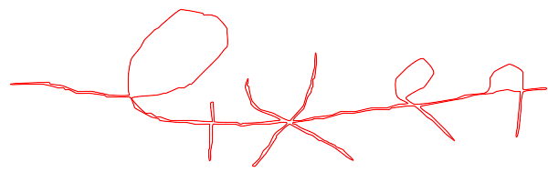
From lpc_tlines.txt, we make a text file of Bézier curves.
pts2bez /ilpc_tlines.txt /olpc_tlines_b.txt /e2 /p7
The first and last five lines of the created text file lpc_tlines.txt are:
stroke cyan line 30.00,10.00 29.95,10.07 line 27.08,16.37 26.00,18.00
stroke lime line 27.95,10.07 31.95,10.07 line 29.95,8.07 29.95,12.07 line 25.08,16.37 29.08,16.37 line 27.08,14.37 27.08,18.37
stroke blue line 28.00,8.00 32.00,12.00 line 32.00,8.00 28.00,12.00 line 24.00,16.00 28.00,20.00 line 28.00,16.00 24.00,20.00
stroke red bezier 30.00,10.00 29.95,10.07 27.08,16.37 26.00,18.00
stroke cyan line 26.00,18.00 25.42,18.88 line 23.58,18.12 23.00,19.00
:
:
stroke red bezier 436.00,350.00 435.80,351.69 435.20,353.31 435.00,355.00
stroke cyan line 435.00,355.00 434.88,356.03 line 433.38,368.85 433.00,372.00
stroke lime line 432.88,356.03 436.88,356.03 line 434.88,354.03 434.88,358.03 line 431.38,368.85 435.38,368.85 line 433.38,366.85 433.38,370.85
stroke blue line 433.00,353.00 437.00,357.00 line 437.00,353.00 433.00,357.00 line 431.00,370.00 435.00,374.00 line 435.00,370.00 431.00,374.00
stroke red bezier 435.00,355.00 434.88,356.03 433.38,368.85 433.00,372.00
We rasterize that drawing:
%IMG7%magick ^ -size 600x400 xc:white ^ -fill None -draw @lpc_tlines_b.txt ^ lpc_tlines_b.png |
|
The scripts traceLines.txt and traceContour.txt create a text file of the coordinates of the white pixels of the input image, grouping the coordinates into lines.
The format of the text file created by traceLines.txt and processed by pts2bez.exe is:
(area and areaedge are not used on this page.)
For loops, the first point should generally be repeated at the end. pts2bez.exe won't enforce this, or do it automatically unless "/a" is used. When isLoop is declared, pts2bez.exe will set the slopes at the two ends of the loop equal to each other. This could also be used to make tilable curves.
The script drawPts.bat is a simple test for the text file, creating an image that is white at each coordinate.
call %PICTBAT%drawPts ^ lpc_tlines.txt lpc_drpts.png |
|
References:
The program pts2bez.exe takes the text of points in lines generated by the previous section, and creates Bézier curves to fit those lines. The source code for my complete program is not available, but the guts of the software can be downloaded: snibFitCurves.h and snibFitCurves.cpp. You will also need GraphicsGems.c and GraphicsGems.h, available from graphicsgems.org, and you will need to build front-end code that populates the FitCurvesT structure.
I added the code for the Douglas-Peucker reduction algorithm, modified the tangent calculations, and added the code to give equal slopes at both ends of loops (closed curves), and the text output for IM and SVG, and some minor housekeeping stuff.
When a line exits and enters the same junction, its first and last pixels will coincide. In addition, other points within the junction may coincide. This causes no problem for snibFitCurve.cpp or pts2bez.exe. When the "/a" option is used, the program will detect when a line starts and ends on the same coordinate, and will then set the tangent gradient (but not length) equal at the ends.
The program creates a text file that contains data for all the graphic lines. There is one text path per line, as a series of joined Bézier curves. Input and output is text; the program isn't linked to IM. Input and output numbers are floating point. The sequence of Bézier curves will pass through the first and last coordinate of the line, and other input coordinates will be within the given tolerance of the generated curve.
In its simplest form ("/f 1"), the output text is like...
Mx1,y1 C x2,y2x3,y3x4,y4,...
... which is usable within SVG, or prefixed by "path" and used in an IM "-draw" command. This can be wrapped in the full syntax for a complete SVG file.
Alternatively, it can issue output as IM "-draw" graphics that shows control points and knots, with straight lines between them.
The program help text is:
pts2bez  v1.0  (c) 2018 Alan Gibson  (GNUC version)

From a list of x,y coordinates, writes joined-up Bezier curves.

Useage:
  pts2bez [options]

Options are:
  /?            display this help
  /i filename   Input text file(s) [stdin]
  /o filename   Output text file [stdout]
  /O filename   append to Output text file
  /p n          for IM draw format, output objects, where n [1] is sum of:
                  1  Bezier
                  2  Points
                  4  Tangents
                  8  Debug
  /e N          Error tolerance, in pixels, floating point [1].
  /n N          Number of output digits after decimal point, integer [2].
  /m N          Minimum tangent length, floating point. 0 = no minimum. [0].
                  Extends to this length, but no longer than segLen/3.
  /a            auto loops.
  /M N          Multiplier for coordinates and related, floating point [1].
  /d N          delta for output coordinates, floating point [0].
  /f N          output format [0], one of:
                  0  IM draw
                  1  MC
                  2  PathMC
                  3  SVG
                  4  IM circles
  /w N          output SVG pixels width, integer [99].
  /h N          output SVG pixels height, integer [99].
  /P            include SVG Path ids.
The error tolerance /e is like a blur, removing high frequency data from curves, smoothing them. The tolerance can be zero, but 0.5 pixels is a more sensible minimum. A value of 2 is needed to avoid staircasing at the pixel level. A large value such as /e10000 will calculate tangent angles based only on end points, so all curves will be straight.
SVG component IDs take time and space, and I don't usually want them. But sometimes we do, for example so we can programatically change properties of individul paths. The program option "/P" will generate IDs, like this:
id="path0032"
When "/a" is used, snibFitCurves.cpp will equalize the slopes at the two ends of a line if the ends coincide.
Schneider's original code takes an array of (x,y) coordinates, and generates a series of joined Bézier curves that pass exactly through the first and last points, and approximately through the others. The slopes at the knots (the angle of the tangents) will point to the next coordinates in the array. If the array is densely populated, the slope can be one of only eight values, which is a crude quantisation. For this reason, reducing the number of points would give finer control over the slopes, improving the result.
But removing points would create another problem. The reduction process removes points within a tolerance of a straight line, but the resulting curve there may not be a straight line, so this can result in large deviations. This is especially noticable when a straight segment ends in a sharp corner: points along the straight will be removed, which allows the corner to become a large radius.
For this reason, snibFitCurves.cpp ignores points for the purpose of calculating tangent angles, but not for the purpose of calculating tangent lengths.
From the points, create a full SVG file:
pts2bez /ilpc_tlines.txt /olpc_4cb4.svg /e2 /f3 /w600 /h400
The first ten and last five lines of lpc_4cb4.svg are:
<?xml version="1.0" standalone="yes"?>
<!DOCTYPE svg PUBLIC "-//W3C//DTD SVG 1.1//EN"
 "http://www.w3.org/Graphics/SVG/1.1/DTD/svg11.dtd">
<svg width="600" height="400"
 xmlns="http://www.w3.org/2000/svg"
 xmlns:xlink="http://www.w3.org/1999/xlink">
<g fill="none" stroke="#000000" stroke-width="1" stroke-linecap="round" stroke-linejoin="round">
<path d="M 30.00,10.00
C 29.95,10.07 27.08,16.37 26.00,18.00
C 25.42,18.88 23.58,18.12 23.00,19.00
:
:
C 434.88,356.03 433.38,368.85 433.00,372.00
z
" />
</g>
</svg>
The SVG file could be optimized for space, but I prefer to have it in a human-readable form. It can be edited in Inkscape, rasterized by IM, shown on web pages, included in PDF documents (via OpenOffice), and so on.
On this page, we use Inkscape as an IM external delegate to rasterize SVG files. But the MSVG internal delegate also works fine:
%IMG7%magick MSVG:lpc_4cb4.svg out.png
|
Rasterize the lpc_4cb4.svg file. %IMG7%magick ^ lpc_4cb4.svg ^ lpc_4cb4.png |
|
|
A blink comparison. %IMG7%magick ^ -loop 0 -delay 50 ^ lpc_4cb4.png -negate ^ curvelines.png ^ lpc_blink.gif Note the 0.5 pixel shift. |
|
|
Being a vector image, we can zoom in
%IMG7%magick ^ -density 360 ^ lpc_4cb4.svg ^ -crop 883x159+871+1343 ^ +repage ^ lpc_4cb4c.png |
|
We may prefer to add an offset of 0.5 to the coordinates in the SVG, so the curves align with the pixels:
pts2bez ^ /ilpc_tlines.txt ^ /o- /e2 /f3 ^ /w600 /h400 ^ /d0.5 | %IMG7%magick ^ -loop 0 -delay 50 ^ - -negate ^ curvelines.png ^ lpc_blink2.gif |

|
We can directly show the SVG image on this web page, with raster fallback in case the browser can't display SVG:
|
lpc_4cb4.svg |
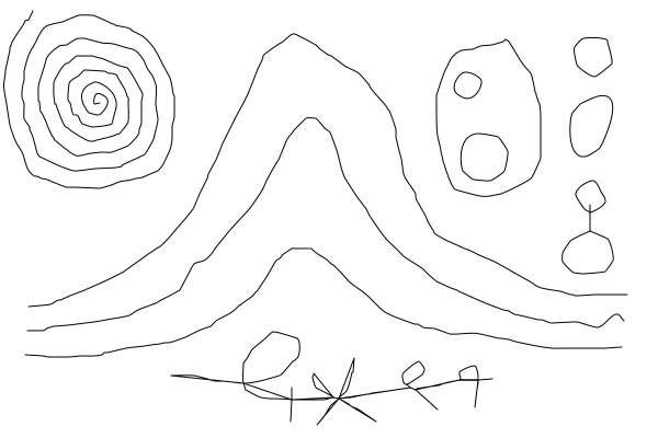
Viewing the SVG file lpc_4cb4.svg with Inkscape, we see that the lines themselves, rather than the boundary of the lines, has been vectorized.
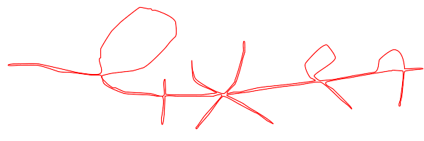
We can pipe in the usual way:
pts2bez ^ /ilpc_tlines.txt ^ /o- /e10 |%IMG7%magick ^ -size 600x400 xc:white ^ -fill none -draw @- ^ lpc_piped.png |
|
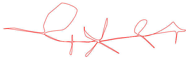
The program pts2bez.exe has a "/m" option (element minTanLen of the FitCurvesT structure). When this is non-zero, tangents shorter than this length will be extended up to that length, but no longer than one-third of the segment length (i.e. the distance between the two ends of the curve segment). The effect is to increase the radius of sharp corners within curves, smoothing them in a different way to "/e". However, this may push curves outside the tolerance, and may cause them to cross each other.
pts2bez ^ /ilpc_tlines.txt ^ /o- /e10 /m100 |%IMG7%magick ^ -size 600x400 xc:white ^ -fill none -draw @- ^ lpc_piped2.png |
|
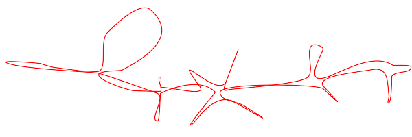
If we add the "/a" option to the pts2bez command, the two joined closed curves on the right reduce their pointedness at the junctions.
pts2bez ^ /ilpc_tlines.txt ^ /o- /a /e10 /m100 |%IMG7%magick ^ -size 600x400 xc:white ^ -fill none -draw @- ^ lpc_piped3.png |

|
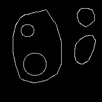
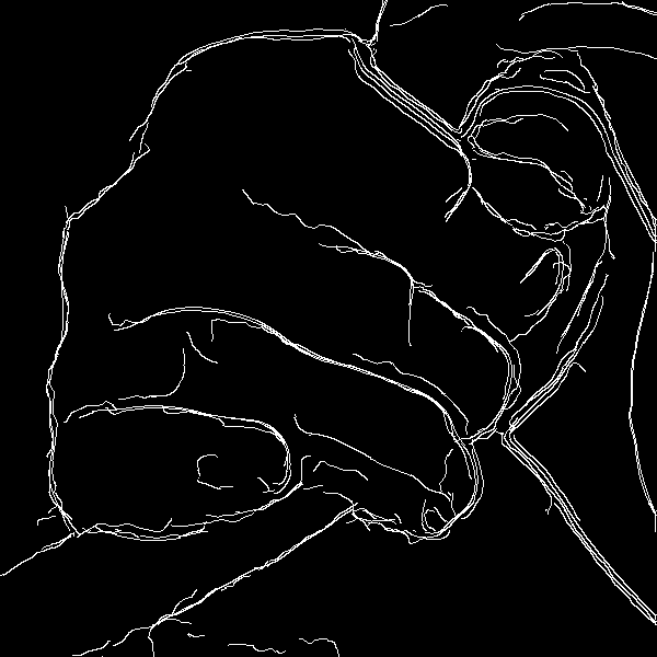
We use an image from the Canny edge detection page.
|
ca_lab.png |
|
rem Next takes about 50 minutes. call %PICTBAT%traceLines ca_lab.png lpc_ca_pts.txt |
[No image] |
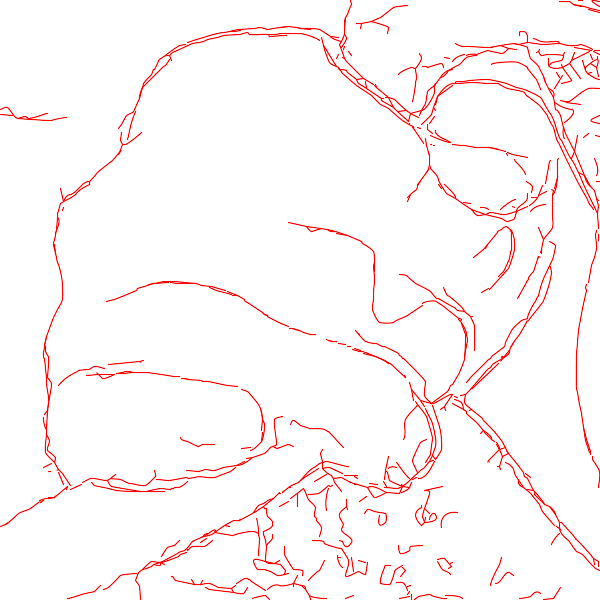
rem Next takes about 0.03 seconds. pts2bez ^ /ilpc_ca_pts.txt ^ /olpc_ca_pts_b.txt /e2 %IMG7%magick ^ -size 600x600 xc:White ^ -fill None -draw @lpc_ca_pts_b.txt ^ lpc_ca_b.png |
|
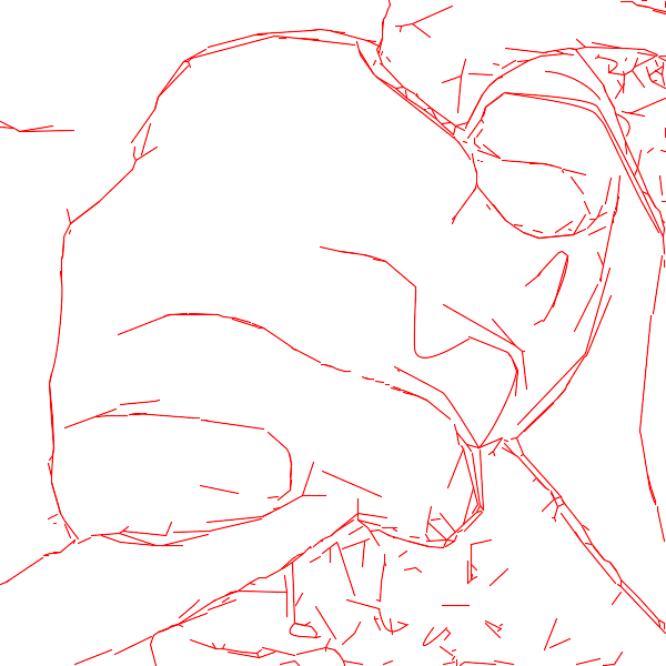
rem Next takes about 0.03 seconds. pts2bez ^ /ilpc_ca_pts.txt ^ /olpc_ca_pts_c.txt /e10 %IMG7%magick ^ -size 600x600 xc:White ^ -fill None -draw @lpc_ca_pts_c.txt ^ lpc_ca_c.png |
|
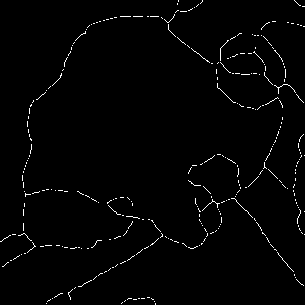
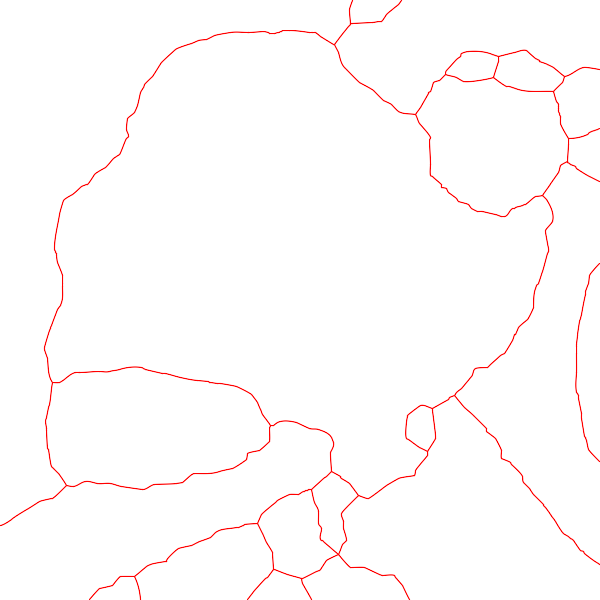
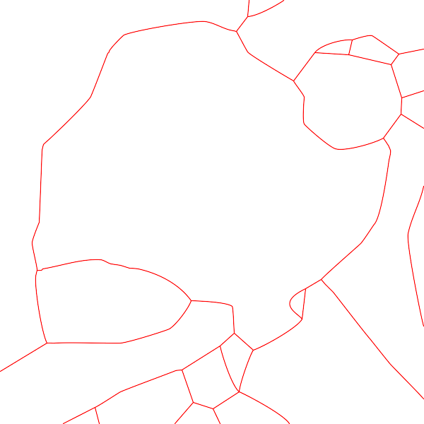
We use an image from the Partition boundary masks page.
|
pb_partbnd4.png |
|
rem Next takes about 3 minutes. call %PICTBAT%traceLines ^ pb_partbnd4.png lpc_pb_pts.txt ^ . . y_XX.png |
[No image] |
pts2bez ^ /ilpc_pb_pts.txt ^ /olpc_pb_pts_b.txt /e2 %IMG7%magick ^ -size 600x600 xc:White ^ -fill None -draw @lpc_pb_pts_b.txt ^ lpc_pb_b.png |
|
pts2bez ^ /ilpc_pb_pts.txt ^ /olpc_pb_pts_c.txt /e10 %IMG7%magick ^ -size 600x600 xc:White ^ -fill None -draw @lpc_pb_pts_c.txt ^ lpc_pb_c.png |
|
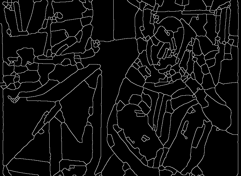
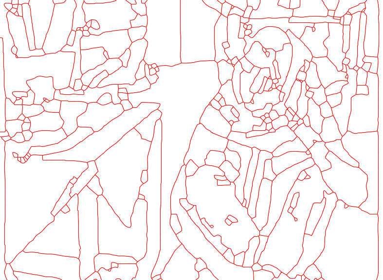
We use another image from the Partition boundary masks page.
|
pb_s2sb_out.png |
|
rem Next takes about one hour. call %PICTBAT%traceLines ^ pb_s2sb_out.png lpc_pbsb_pts.txt ^ . . y2_XX.png |
[No image] |
pts2bez ^ /ilpc_pbsb_pts.txt ^ /olpc_pbsb_pts_b.txt /e2 %IMG7%magick ^ -size 787x576 xc:White ^ -fill None -draw @lpc_pbsb_pts_b.txt ^ lpc_pbsb_b.png |
|
pts2bez ^ /ilpc_pbsb_pts.txt ^ /olpc_pbsb_pts_c.txt /e10 %IMG7%magick ^ -size 787x576 xc:White ^ -fill None -draw @lpc_pbsb_pts_c.txt ^ lpc_pbsb_c.png |
|
The simple script walkPix.bat animates the drawing of lines. It creates one image per pixel, in memory, and creates an animated GIF from them.
Beware of memory problems if the input is large with many white pixels.
%IMG7%magick ^ curvelines.png ^ -crop 308x103+151+294 +repage ^ -fill Black ^ -draw "rectangle 0,0 53,26" ^ -draw "rectangle 215,0 308,22" ^ +write lpc_xlns.png ^ -fill White -colorize 100 ^ lpc_xlns_w.png |
|
call %PICTBAT%traceLines ^ lpc_xlns.png lpc_xlns_pts.txt if ERRORLEVEL 1 goto error call %PICTBAT%walkPix ^ lpc_xlns_w.png ^ lpc_xlns_pts.txt ^ lpc_xlns.gif |

|
Lines are not always drawn in the order I would like. I hope to improve this, for example by preferring to start line at "free" ends, rather than ends at junctions.
walkPix2.bat is a smarter script that creates each image, after the first, as size 1x1 with the appropriate offset, effectively doing the "-layers compress" as it progresses.
%IMG7%magick ^ pb_s2sb_out.png ^ -fill #ccf -colorize 100 ^ pb_s2sb_out_w.png call %PICTBAT%walkPix2 ^ pb_s2sb_out_w.png ^ lpc_pbsb_pts.txt ^ lpc_pbsb.gif |

|
Scripts shown here trace lines (and create Bézier curves) in proximity order: after tracing the last pixel of a line, they search for the closest end of another line. For some operations such as cutting physical materials, we would want to cut all open curves before any closed curves. The scripts might be extended to do this.
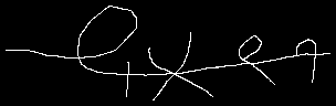
A more intelligent line-ordering would need a more global view. For example, the crossed lines at the bottom of curvelines.png is essentially one long line that crosses itself, and five smaller lines that cross the long line.
The script traceLines.bat is painfully slow. It might serve as a reference implementation for a Magick++ program, process module or whatever. (An unpublished C-program equivalent, using MagickCore, is substantially faster.)
We might measure the width of lines, and record them for use when drawing Bézier curves. (darkestpntpnt could calculate nInPath/maxDist.)
The library snibFitCurves.cpp and program pts2bez.exe always creates Bézier curves, even for segments that are straight. I might provide an option for detecting "virtually straight", and emitting them as straight lines.
The library snibFitCurves.cpp and program pts2bez.exe can create control points outside the bounding rectangle of the knots, so curves can be created outside the image boundary. An option could be added to clip the control tangent lengths at image boundaries.
When we rasterize a vectorized raster line, we are effectively moving pixels. That is, we are distorting the image edges spatially. Perhaps we could extend this, to also move colour data.
Interesting effects might come from tolerating greater errors at coordinates more distant from junctions.
If we really want to vectorize the boundary of thin lines, snibFitCurves.cpp ComputeMaxError() could be tweaked so it didn't tolerate any curve that was on the wrong side of the input line.
Inkscape can flood-fill areas by finding which paths bound an area, and rearranging those paths into a continuous closed path. This technique could also be used to simplify the result by eliminating small areas (merging the nodes).
For convenience, .bat scripts are also available in a single zip file. See Zipped BAT files.
rem From image %1, a white shape on black background,
rem trace the contour, writing coordinates to text file %2.
rem Tracing starts at nearest white pixel to coord %3,%4 [0,0],
rem   which should be an end-line.
rem %5 is offset to be applied. Use half the line width. [0.5]
rem
rem This assumes shape has more than one white pixel.


@if "%2"=="" findstr /B "rem @rem" %~f0 & exit /B 1

@setlocal enabledelayedexpansion

@call echoOffSave

call %PICTBAT%setInOut %1 tc

set OUTFILE=%2

set firstX=%3
if "%firstX%"=="." set firstX=
if "%firstX%"=="" set firstX=0

set firstY=%4
if "%firstY%"=="." set firstY=
if "%firstY%"=="" set firstY=0

set offs=%5
if "%offs%"=="." set offs=
if "%offs%"=="" set offs=0.5

rem FIXME: We need to start at a line-end.

set INTRO=
for /F "usebackq tokens=1-3 delims=:, " %%A in (`%IM7DEV%magick ^
  %INFILE% ^
  -process 'nearestwhite cx %firstX% cy %firstY%' ^
  NULL: 2^>^&1`) do (
  set INTRO=%%A
  set pX=%%B
  set pY=%%C
)

if not "%INTRO%"=="nearestwhite" exit /B 1

if "%pX%"=="none" exit /B 1

set TMPDIR=\temp\
set TMPIN=%TMPDIR%tc.miff
set TMPOUT=%TMPDIR%tc.txt

%IMG7%magick ^
  %INFILE% ^
  -colorspace Gray ^
  -threshold 50%% ^
  -depth 8 ^
  %TMPIN%

set /A prevX=%pX%-1
set /A prevY=%pY%

rem We need to have both pxy and prevxy on boundary,
rem then we can store the original values and start emitting.
rem Beware isolated white pixels,
rem or being surrounded by white.

:: While prevXY is not white, get next

set cnt=0
:getWhite
call :nextClockwise

for /F "usebackq" %%L in (`%IMG7%magick ^
  %TMPIN% ^
  -format "isW=%%[fx:p{%cX%,%cY%}]\n" ^
  info:`) do set %%L

set /A cnt+=1

if %cnt%==9 (
  echo All neighbours are black.
  exit /B 1
)

set prevX=%cX%
set prevY=%cY%

if %isW%==0 goto getWhite


:: While prevXY is white, get next

set cnt=0
:getBlack
call :nextClockwise

for /F "usebackq" %%L in (`%IMG7%magick ^
  %TMPIN% ^
  -format "isW=%%[fx:p{%cX%,%cY%}]\n" ^
  info:`) do set %%L

set /A cnt+=1

if %cnt%==9 (
  echo All neighbours are white.
  exit /B 1
)

if %isW%==1 (
  set prevX=%cX%
  set prevY=%cY%
  goto getBlack
)

rem echo %prevX%,%prevY% is last white

rem Pretend we emitted the previous, for the offsets.
rem (With new scheme, no longer need this.)
set eX=%prevX%
set eY=%prevY%

echo %0: eXY=%eX%,%eY% pXY=%pX%,%pY%

for /F "usebackq" %%L in (`%IMG7%magick ^
  xc: ^
  -format "oX=%%[fx:%pX%+(%pY%-%eY%)*%offs%]\noY=%%[fx:%pY%-(%pX%-%eX%)*%offs%]\n" ^
  info:`) do set %%L

del %TMPOUT% 2>nul
rem echo %oX%,%oY% >%TMPOUT%

set eX=%pX%
set eY=%pY%

set firstpX=%pX%
set firstpY=%pY%
set firstprevX=%prevX%
set firstprevY=%prevY%

call :nextClockwise

echo %0: firstpXY %firstpX%,%firstpY%  firstprevXY %firstprevX%,%firstprevY%

rem eXY is the previously emitted coordinate.
rem If we always start at an end, perhaps we don't need eXY, or that test.
rem Yes, we need eXY for the offsets.

set savedStart=0

set numPts=0
:loop

for /F "usebackq" %%L in (`%IMG7%magick ^
  %TMPIN% ^
  -format "isW=%%[fx:p{%cX%,%cY%}]\n" ^
  info:`) do set %%L

if %isW%==1 (

  for /F "usebackq" %%L in (`%IMG7%magick ^
    xc: ^
    -format "oX=%%[fx:%cX%+(%cY%-%eY%)*%offs%]\noY=%%[fx:%cY%-(%cX%-%eX%)*%offs%]\n" ^
    info:`) do set %%L

  set prevX=%pX%
  set prevY=%pY%
  set pX=%cX%
  set pY=%cY%
  set eX=%cX%
  set eY=%cY%
rem  echo !oX!,!oY! >>%TMPOUT%
rem  set /A numPts+=1
) else (
  call :emitBoundary %pX% %pY% %cX% %cY%

  set prevX=%cX%
  set prevY=%cY%
)

call :nextClockwise

if not %firstpX%==%cX% goto loop
if not %firstpY%==%cY% goto loop
if not %firstprevX%==%eX% goto loop
if not %firstprevY%==%eY% goto loop

rem Repeat the first point.
set cX=%firstpX%
set cY=%firstpY%
set eX=%firstprevX%
set eY=%firstprevY%

for /F "usebackq" %%L in (`%IMG7%magick ^
  xc: ^
  -format "oX=%%[fx:%cX%+(%cY%-%eY%)*%offs%]\noY=%%[fx:%cY%-(%cX%-%eX%)*%offs%]\n" ^
  info:`) do set %%L

rem echo !oX!,!oY! >>%TMPOUT%
rem set /A numPts+=1

if %savedStart%==1 (
  echo %startX%,%startY% >>%TMPOUT%
  set /A numPts+=1
)

echo isLoop >>%TMPOUT%


echo %0: numPts=%numPts%


echo line >%OUTFILE%
echo numPts=%numPts% >>%OUTFILE%
type %TMPOUT% >>%OUTFILE%

call echoRestore

@endlocal & set tlnOUTFILE=%OUTFILE%

@exit /B 0

::--------------------------------
:: Subroutines

:: Of the 8 neighbours of px,py,
:: set cX,cY to next neighbour after prevX,prevY in clockwise direction.

:nextClockwise

set /A dx=%prevX%-%pX%
set /A dy=%prevY%-%pY%

if %dx%==-1 (
  set /A dy-=1
  if /I !dy! LSS -1 (
    set /A dy=-1
    set /A dx+=1
  )
) else if %dx%==1 (
  set /A dy+=1
  if /I !dy! GTR 1 (
    set /A dy=1
    set /A dx-=1
  )
) else if %dy%==-1 (
  set /A dx+=1
) else (
  set /A dx-=1
)

set /A cX=%pX%+(%dx%)
set /A cY=%pY%+(%dy%)

exit /B 0


:emitBoundary

if not %1==%3 if not %2==%4 exit /B 0

for /F "usebackq" %%L in (`%IMG7%magick ^
  xc: ^
  -format "oX=%%[fx:(%1+%3)/2+%offs%]\noY=%%[fx:(%2+%4)/2+%offs%]\n" ^
  info:`) do set %%L

echo %oX%,%oY% >>%TMPOUT%

if %savedStart%==0 (
  set savedStart=1
  set startX=%oX%
  set startY=%oY%
)

set /A numPts+=1

exit /B 0
rem Given image %1, white points on black background,
rem where groups of 4- or 8-connected points form zero or more non-crossing lines,
rem traces the coordinates of one line from coord %2,%3
rem appending to text file %4, with no header.
@rem
@rem Updated:
@rem   14-September-2022 for IM v7.
@rem

@setlocal enabledelayedexpansion

set INFILE=%1
set firstX=%2
set firstY=%3
set OUTFILE=%4

%IM7DEV%magick ^
  %INFILE% ^
  -channel RGB ^
    -negate ^
    -evaluate Add 1 ^
  +channel ^
  -process 'darkestpntpnt s %firstX%,%firstY% e %firstX%,%firstY% t 0.5 no_end p f stdout data' ^
  NULL: >>%OUTFILE%

if ERRORLEVEL 1 exit /B 1

set numPts=0
for /F "tokens=1,2 delims=, " %%X in (%OUTFILE%) do (
  set lastX=%%X
  set lastY=%%Y
  set /A numPts+=1
)

@endlocal& set tlNumPts=%numPts%& set tlLastX=%lastX%& set tlLastY=%lastY%
rem Given image %1, white points on black background, entirely opaque,
rem where groups of 4- or 8-connected points form zero or more non-crossing lines,
rem writes text file %2 of the points.
rem starting from coord %3,%4 [0,0]
@rem
@rem This will ignore loops.
@rem If we have two lines each with only one end, it won't work properly.
@rem This won't process line-crossings (ie junctions) as I want.
@rem
@rem Updated:
@rem   14-September-2022 for IM v7.
@rem

@rem FIXME: option to supress header.
@rem FIXME: add black border?


@if "%2"=="" findstr /B "rem @rem" %~f0 & exit /B 1

@setlocal enabledelayedexpansion

@call echoOffSave

call %PICTBAT%setInOut %1 l2p

set OUTFILE=%2


set TMPDIR=\temp\
if not exist %TMPDIR% md %TMPDIR%

set TMPEXT=.miff

set TMPIN=%TMPDIR%l2p_tmp_in%TMPEXT%
set ENDS=%TMPDIR%l2p_ends%TMPEXT%
set ONELNPTS=%TMPDIR%l2p_oneln.lis

set CONV=%IMDEV%convert


set numEnds=

for /F "usebackq" %%L in (`%IMG7%magick ^
  %INFILE% ^
  -alpha off ^
  ^( +clone ^
     -channel RGB ^
       -negate ^
       -evaluate Add 1 ^
     +channel ^
     -write %TMPIN% ^
     +delete ^
  ^) ^
  -bordercolor Black -border 1 ^
  -morphology HMT LineEnds ^
  -shave 1x1 ^
  -format "numEnds=%%[fx:int(mean*w*h+0.5)]\nnumLines=%%[fx:int(mean*w*h/2+0.5)]" ^
  +write info: ^
  %ENDS%`) do set %%L

if "%numEnds%"=="" exit /B 1

echo numLines=%numLines% >%OUTFILE%

if %numLines%==0 (
  echo %0: numLines is zero. INFILE=%INFILE%
  goto end
)

set lastX=%3
set lastY=%4

if "%lastX%"=="." set lastX=
if "%lastX%"=="" set lastX=0

if "%lastY%"=="." set lastY=
if "%lastY%"=="" set lastY=0

set actEnds=0

:: FIXME: BUG: This loop can be endless, when darkestpntpnt has start and end above threshold.

:loop

set INTRO=

for /F "usebackq tokens=1-3 delims=:, " %%A in (`%IM7DEV%magick ^
  %ENDS% ^
  -process 'nearestwhite cx %lastX% cy %lastY%' ^
  NULL: 2^>^&1`) do (
  set INTRO=%%A
  set firstX=%%B
  set firstY=%%C
)

if not "%INTRO%"=="nearestwhite" exit /B 1
if "%firstX%"=="none" goto noMore

:: FIXME: BUG in darkestpntpnt for v7??

%IM7DEV%magick ^
  %TMPIN% ^
  -process 'darkestpntpnt s %firstX%,%firstY% e %firstX%,%firstY% t 0.5 no_end print file stdout data' ^
  NULL: >%ONELNPTS%

set numPts=0
for /F %%L in (%ONELNPTS%) do set /A numPts+=1

echo line >>%OUTFILE%
echo numPts=%numPts% >>%OUTFILE%
for /F "tokens=1,2 delims=, " %%X in (%ONELNPTS%) do (
  set lastX=%%X
  set lastY=%%Y
  echo %%X,%%Y >>%OUTFILE%
)

echo %0: firstX=%firstX% firstY=%firstY% lastX=%lastX% lastY=%lastY%

rem 15-September-2022 also do this in TMPIN to avoid repeating same lastXY ??
%IMG7%magick ^
  %ENDS% ^
  -fill Black ^
  -draw "point %firstX%,%firstY% point %lastX%,%lastY%" ^
  %ENDS%

set /A actEnds+=2

goto loop

:noMore

if not %numEnds%==%actEnds% (
  echo %0: numEnds is %numEnds% but actEnds is %actEnds%
  rem 15-September-2022 warning, not error.
)

:end

call echoRestore

@endlocal & set l2pOUTFILE=%OUTFILE%&set l2pNumPts=%numPts%& set l2pLastX=%lastX%& set l2pLastY=%lastY%
rem Given image %1, white points on black background, fully opaque,
rem where groups of 4- or 8-connected points form lines,
rem writes the coordinates of lines to text file %2
rem starting from line-end nearest to coord %3,%4 [0,0]
rem
rem %5 optional template filename for saved debugging images.
rem   Must contain XX, which will be replaced
rem   by skel, lines, jcns, ends, loops, lpbrk.
@rem
@rem Last update:
@rem
@rem   9-Jan-2017 Write width and height.
@rem   14-September-2022 for IM v7.
@rem


@if "%2"=="" findstr /B "rem @rem" %~f0 & exit /B 1

@setlocal enabledelayedexpansion

@call echoOffSave

call %PICTBAT%setInOut %1 tln

set OUTFILE=%2

set firstX=%3
if "%firstX%"=="." set firstX=
if "%firstX%"=="" set firstX=0

set firstY=%4
if "%firstY%"=="." set firstY=
if "%firstY%"=="" set firstY=0

set DBG_TMPLT=%5
if "%DBG_TMPLT%"=="." set DBG_TMPLT=


set TMPDIR=\temp\
if not exist %TMPDIR% md %TMPDIR%

set TMPEXT=.miff


set SKEL=%TMPDIR%tl_skel%TMPEXT%

set LINES=%TMPDIR%tl_lines%TMPEXT%
set JCNS=%TMPDIR%tl_jcns%TMPEXT%
set JCNSROT=%TMPDIR%tl_jcns_rot%TMPEXT%
set ENDS=%TMPDIR%tl_ends%TMPEXT%
set LPBRK=%TMPDIR%tl_lpbrk%TMPEXT%

set LOOPS=%TMPDIR%tl_loops%TMPEXT%
set ONEJCN=%TMPDIR%tl_1jcn%TMPEXT%

set ENDS_LIST=%TMPDIR%tl_ends.lis
set PARTLIST=%TMPDIR%tl_part.txt

del %OUTFILE% 2>nul
del %PARTLIST% 2>nul

if "%DBG_TMPLT%"=="" (
  set wrSKEL=
) else (
  set wrSKEL=+write %DBG_TMPLT:XX=skel%
)

%IMG7%magick ^
  %INFILE% ^
  -alpha off ^
  -virtual-pixel Edge ^
  -morphology Thinning:-1 Skeleton -clamp ^
  -threshold 50%% ^
  -alpha off ^
  %wrSKEL% ^
  ( +clone ^
    -virtual-pixel Black ^
    -define morphology:compose=Darken ^
    -morphology Thinning ^
      "LineJunctions;LineJunctions:3>;LineJunctions:5" ^
    -clamp ^
    -morphology Thinning ^
      "3x3:0,0,0,0,1,0,0,0,0" ^
    -clamp -alpha off ^
    +write %LINES% ^
  ) ^
  -compose Difference -composite ^
  %JCNS%

for /F "usebackq" %%L in (`%IMG7%magick ^
  %JCNS% ^
  -rotate 180 ^
  +write %JCNSROT% ^
  -format "WW=%%w\nHH=%%h\nWm1=%%[fx:w-1]\nHm1=%%[fx:h-1]" ^
  info:`) do set %%L

(
  echo width=%WW%
  echo height=%HH%
) >%OUTFILE%

%IMG7%magick ^
  %LINES% ^
  -virtual-pixel Black ^
  -define morphology:compose=Lighten ^
  -morphology HMT LineEnds;3x3:0,0,0,0,1,0,0,0,0 ^
  -clamp -alpha off ^
  %ENDS%

%IM7DEV%magick ^
  %ENDS% ^
  -process allwhite ^
  NULL: 2>%ENDS_LIST%

call %PICTBAT%fillCoords ^
  %LINES% ^
  %ENDS_LIST% ^
  black ^
  %LOOPS%

if ERRORLEVEL 1 exit /B 1

call %PICTBAT%clc2lpbrk ^
  %LOOPS% ^
  %LPBRK%

if ERRORLEVEL 1 exit /B 1

%IMG7%magick ^
  %LINES% ^
  ( %LPBRK% -negate ) ^
  -compose Darken -composite ^
  +write %LINES% ^
  -virtual-pixel Black ^
  -define morphology:compose=Lighten ^
  -morphology HMT LineEnds;3x3:0,0,0,0,1,0,0,0,0 ^
  -clamp -alpha off ^
  %ENDS%

if not "%DBG_TMPLT%"=="" (

  %IMG7%magick ^
    %LINES% -write %DBG_TMPLT:XX=lines% +delete ^
    %JCNS%  -write %DBG_TMPLT:XX=jcns%  +delete ^
    %ENDS%  -write %DBG_TMPLT:XX=ends%  +delete ^
    %LPBRK% -write %DBG_TMPLT:XX=lpbrk% +delete ^
    %LOOPS% -write %DBG_TMPLT:XX=loops% ^
    NULL:
)


set lastX=%firstX%
set lastY=%firstY%
set actEnds=0
set doTestExit=1

:loop

call :findNearest %ENDS% %lastX% %lastY%
if ERRORLEVEL 1 exit /B 1
if "%firstX%"=="none" goto noMore

rem Save first coord in case this is a loop.
set loopStart=%firstX%,%firstY%

set endX=%firstX%
set endY=%firstY%

if %doTestExit%==0 goto skipTestExit

rem If this line leaves a jcn, also include that. (Jcn exit.)
call :findNearest %JCNS% %endX% %endY%
if ERRORLEVEL 1 exit /B 1
set /A dxy=(%endX%-%firstX%)*(%endX%-%firstX%)+(%endY%-%firstY%)*(%endY%-%firstY%)
if /I %dxy% LEQ 2 (
  echo %0: trace jcn exit: end = %endX%,%endY%

  for /F "usebackq tokens=1,2 delims=, " %%X in (`%IM7DEV%magick ^
    %JCNS% ^
    ^( +clone ^
       -fill Black ^
       -draw "color %firstX%,%firstY% floodfill" ^
    ^) ^
    -compose Difference -composite ^
    -process midlightest ^
    %ONEJCN% 2^>^&1`) do (
    set MX=%%X
    set MY=%%Y
  )

  echo %0: trace jcn exit: !MX!,!MY! to %firstX%,%firstY% for %endX%,%endY%

  %IM7DEV%magick ^
    %ONEJCN% ^
    -negate -evaluate Add 1 ^
    -process 'darkestpntpnt s !MX!,!MY! e %firstX%,%firstY% t 0.5' ^
    -negate -evaluate Add 1 ^
    -process 'darkestpntpnt s !MX!,!MY! e %firstX%,%firstY% t 0.5 no_end p f stdout data' ^
    NULL: >>%PARTLIST%

  echo # jcn exit !MX!,!MY! to %firstX%,%firstY% for %endX%,%endY% >>%PARTLIST%
)

:skipTestExit
set doTestExit=1

call %PICTBAT%traceLn %LINES% %endX% %endY% %PARTLIST%

echo %0: Line traced: tlNumPts=%tlNumPts% tlLastX=%tlLastX% tlLastY=%tlLastY%

set lastX=%tlLastX%
set lastY=%tlLastY%

:: Remove both from ENDS.
%IMG7%magick ^
  %ENDS% ^
  -fill Black ^
  -draw "point %endX%,%endY% point %lastX%,%lastY%" ^
  %ENDS%


:: Find next coord from JCNS or LPBRK.

:: FIXME: optimize next stuff:
::   if jcn is neighbour, no need to find nearest loop brk, etc.

set /A xr=%Wm1%-%lastX%
set /A yr=%Hm1%-%lastY%
call :findNearest %JCNSROT% %xr% %yr%
if ERRORLEVEL 1 exit /B 1
if "%firstX%"=="none" (
  set sqJ=99999
) else (
  set /A nrJcnX=%Wm1%-%firstX%
  set /A nrJcnY=%Hm1%-%firstY%
  set /A "sqJ=(%lastX%-!nrJcnX!)*(%lastX%-!nrJcnX!)+(%lastY%-!nrJcnY!)*(%lastY%-!nrJcnY!)"
)

set sqB=99999

if /I %sqJ% GTR 2 (
  call :findNearest %LPBRK% %lastX% %lastY%
  if ERRORLEVEL 1 exit /B 1
  if "!firstX!"=="none" (
    set sqB=99999
  ) else (
    set nrBrkX=!firstX!
    set nrBrkY=!firstY!
    set /A "sqB=(%lastX%-!nrBrkX!)*(%lastX%-!nrBrkX!)+(%lastY%-!nrBrkY!)*(%lastY%-!nrBrkY!)"
  )
)

echo %0: sqJ=%sqJ% sqB=%sqB%

if /I %sqJ% LEQ 2 (
  echo %0: trace junction %nrJcnX%,%nrJcnY%
  call :traceJcn %nrJcnX% %nrJcnY%
  if ERRORLEVEL 1 exit /B 1
) else if /I %sqB% LEQ 2 (
  echo %0: trace loop-break %nrBrkX%,%nrBrkY%
  call %PICTBAT%traceLn %LPBRK% %nrBrkX% %nrBrkY% %PARTLIST%
  if ERRORLEVEL 1 exit /B 1

  echo %0: Loop-break: tlNumPts=!tlNumPts! tlLastX=!tlLastX! tlLastY=!tlLastY!
  set lastX=!tlLastX!
  set lastY=!tlLastY!

  rem Remove loop-break from %LPBRK%. There can only be two points?
  %IMG7%magick ^
    %LPBRK% ^
    -fill Black ^
    -draw "point %nrBrkX%,%nrBrkY% point !lastX!,!lastY!" ^
    %LPBRK%

  rem Repeat first coord of loop
  echo %loopStart% >>%PARTLIST%
  call :cumulCoords
  echo isLoop >>%OUTFILE%

) else (
  echo %0: trace next line %lastX%,%lastY%

  call :cumulCoords
)

if not %lastX%==none goto loop

:noMore

call :cumulCoords

:: Check that %ENDS% and %LPBRK% are entirely black.

for /F "usebackq" %%L in (`%IMG7%magick ^
  %ENDS% ^
  -format "minEnds=%%[fx:minima]\n" ^
  +write info: ^
  +delete ^
  %LPBRK% ^
  -format "minLpbrk=%%[fx:minima]\n" ^
  info:`) do set %%L

if not %minEnds%==0 (
  echo # minEnds=%minEnds% >>%OUTFILE%
  echo %0: minEnds=%minEnds%
  exit /B 1
)

if not %minLpbrk%==0 (
  echo # minLpbrk=%minLpbrk% >>%OUTFILE%
  echo %0: minLpbrk=%minLpbrk%
  exit /B 1
)

del %ENDS%
del %LPBRK%

echo # finished >>%OUTFILE%
echo %0: finished

call echoRestore

@endlocal & set tlnOUTFILE=%OUTFILE%

@exit /B 0

::-------------------------------------------------
:: Subroutines

:: Parameters: image file, centre x, center y.
:findNearest
set INTRO=
for /F "usebackq tokens=1-3 delims=:, " %%A in (`%IM7DEV%magick ^
  %1 ^
  -process 'nearestwhite cx %2 cy %3' ^
  NULL: 2^>^&1`) do (
  set INTRO=%%A
  set firstX=%%B
  set firstY=%%C
)
if ERRORLEVEL 1 exit /B 1

if not "%INTRO%"=="nearestwhite" exit /B 1

if "%firstY%"=="" set firstY=99999

rem echo %0: p1=%1 p2=%2 p3=%3 firstX=%firstX% firstY=%firstY%

exit /B 0

::-------------------------------------------------

:: Parameters: startX, startY
:: Traces path to center.
:: Returns coord on other side of center.
:: Assumes jcn is 4-connected.

:traceJcn

for /F "usebackq tokens=1,2 delims=, " %%X in (`%IM7DEV%magick ^
  %JCNS% ^
  ^( +clone ^
     -fill Black ^
     -draw "color %1,%2 floodfill" ^
  ^) ^
  -compose Difference -composite ^
  -process midlightest ^
  %ONEJCN% 2^>^&1`) do (
  set MX=%%X
  set MY=%%Y
)
echo %0: trace jcn part 1: %1,%2 to !MX!,!MY!
echo # jcn part 1: %1,%2 to !MX!,!MY! >>%PARTLIST%

set /A FX=2*!MX!-%1
set /A FY=2*!MY!-%2

rem echo %0: FX=!FX! FY=!FY!

set doit=1
if %1==!MX! if %2==!MY! set doit=0

if %doit%==0 (
  echo %1,%2 >>%PARTLIST%
) else (
  %IM7DEV%magick ^
    %ONEJCN% ^
    -negate -evaluate Add 1 ^
    -process 'darkestpntpnt s %1,%2 e !MX!,!MY! t 0.5' ^
    -negate -evaluate Add 1 ^
    -process 'darkestpntpnt s %1,%2 e !MX!,!MY! t 0.5 no_end p f stdout data' ^
    NULL: >>%PARTLIST%
)

call :cumulCoords

:: Find nearest end.
call :findNearest %ENDS% !FX! !FY!
set endX=!firstX!
set endY=!firstY!
:: If endXY is neighbour of the junction, trace from MXY to it.
call :findNearest %ONEJCN% !endX! !endY!
set /A dxy=(!endX!-%firstX%)*(!endX!-%firstX%)+(!endY!-%firstY%)*(!endY!-%firstY%)
if /I %dxy% LEQ 2 (

  set doTestExit=0

  set doit=1
  if !firstX!==!MX! if !firstY!==!MY! set doit=0

  if !doit!==0 (
    echo %0: trace jcn part 2: ... to !firstX!,!firstY! for %endX%,%endY%
    echo !firstX!,!firstY! >>%PARTLIST%
  ) else (
    echo %0: trace jcn part 2: %MX%,%MY% to !firstX!,!firstY! for %endX%,%endY%
    %IM7DEV%magick ^
      %ONEJCN% ^
      -negate -evaluate Add 1 ^
      -process 'darkestpntpnt s !MX!,!MY! e !firstX!,!firstY! t 0.5' ^
      -negate -evaluate Add 1 ^
      -process 'darkestpntpnt s !MX!,!MY! e !firstX!,!firstY! t 0.5 no_end p f stdout data' ^
      NULL: >>%PARTLIST%
  )
  echo # jcn part 2 !MX!,!MY! to !firstX!,!firstY! for %endX%,%endY% >>%PARTLIST%
) else (
  echo %0: no jcn part 2: endXY=%endX%,%endY%  firstXY=!firstX!,!firstY!  dxy=%dxy%
)

set lastX=%firstX%
set lastY=%firstY%

exit /B 0

::-------------------------------------------------

:cumulCoords

set numPts=0
if exist %PARTLIST% for /F %%L in (%PARTLIST%) do (
  set LINE=%%L
  if not "!LINE:~0,1!"=="#" set /A numPts+=1
)

if /I %numPts% GTR 0 (
  ( echo line
    echo numPts=%numPts%
    for /F "tokens=*" %%L in (%PARTLIST%) do echo %%L
  ) >>%OUTFILE%
)

del %PARTLIST% 2>nul

exit /B 0
rem Given image %1,
rem %2 text list of coordinates (after 1-line header),
rem colour %3 [black]
rem fill at each coordinate, output to %4.
@rem
@rem Updated:
@rem   14-September-2022 for IM v7.
@rem

setlocal enabledelayedexpansion

set INFILE=%1
set COORDS=%2
set COL=%3
set OUTFILE=%4

if "%COL%"=="." set COL=
if "%COL%"=="" set COL=black

set FC_SCR=\temp\fc_scr.scr

@(
  @for /F "skip=1" %%L in (%COORDS%) do @echo color %%L floodfill
) >%FC_SCR%

%IMG7%magick ^
  %INFILE% ^
  -morphology thicken "3>:-,0,-,1,-,1,0,1,0" ^
  -morphology thicken "3>:-,0,0,1,-,0,0,1,-" ^
  -clamp ^
  -fill %COL% ^
  -draw @%FC_SCR% ^
  %OUTFILE%

endlocal
rem Given image %1,
rem %2 same-size mask with some white pixels,
rem colour %3 [black]
rem flood-fill %1 at each white in mask, output to %4.
@rem
@rem Updated:
@rem   14-September-2022 for IM v7.
@rem

setlocal enabledelayedexpansion

set INFILE=%1
set MASK=%2
set COL=%3
set OUTFILE=%4

if "%COL%"=="." set COL=
if "%COL%"=="" set COL=black

set FC_SCR=\temp\fp_scr.scr

(
  for /F "usebackq skip=1" %%L in (`%IM7DEV%magick ^
    %MASK% ^
    -process allwhite ^
    NULL: 2^>^&1`) do @echo color %%L floodfill
) >%FC_SCR%

%IMG7%magick ^
  %INFILE% ^
  -morphology thicken "3>:-,0,-,1,-,1,0,1,0" ^
  -morphology thicken "3>:-,0,0,1,-,0,0,1,-" ^
  -alpha off -clamp ^
  -fill %COL% ^
  -draw @%FC_SCR% ^
  %OUTFILE%

endlocal
rem Given opaque image %1 of white loops only,
rem make image %2 of white pixels that break the loops,
rem otherwise black.
@rem
@rem Updated:
@rem   14-September-2022 for IM v7.
@rem

@if "%2"=="" findstr /B "rem @rem" %~f0 & exit /B 1

@setlocal enabledelayedexpansion

@call echoOffSave

call %PICTBAT%setInOut %1 c2lb

set OUTFILE=%2


set TMPDIR=\temp\
if not exist %TMPDIR% md %TMPDIR%

set TMPEXT=.miff

set TMPIN=%TMPDIR%c2p_tmpin%TMPEXT%
set BRK=%TMPDIR%c2p_brk%TMPEXT%
set LPBK=%TMPDIR%c2p_lpbk%TMPEXT%

%IMG7%magick ^
  %INFILE% ^
  -alpha off ^
  -morphology Thinning:-1 Skeleton ^
  -alpha off -clamp ^
  +write %TMPIN% ^
  +write %BRK% ^
  -fill Black -colorize 100 ^
  -alpha off ^
  %LPBK%

if ERRORLEVEL 1 exit /B 1


:multiLoop

set numEnds=

for /F "usebackq" %%L in (`%IMG7%magick ^
  %BRK% ^
  -alpha off ^
  -format "maxVal=%%[fx:maxima]\n" ^
  +write info: ^
  -morphology HMT LineEnds ^
  -alpha off -clamp ^
  -format "numEnds=%%[fx:int(mean*w*h+0.5)]\n" ^
  info:`) do set %%L

if not "%numEnds%"=="0" (
  echo %0: numEnds=%numEnds%
  exit /B 1
)

echo %0: numEnds=%numEnds% maxVal=%maxVal%

if %maxVal%==0 goto finished

%IMG7%magick ^
  %BRK% ^
  -alpha off ^
  %TMPIN%

:brkLoop
:: Break a loop
for /F "usebackq tokens=1-3 delims=:, " %%A in (`%IM7DEV%magick ^
  %TMPIN% ^
  -alpha off ^
  -process onewhite ^
  NULL: 2^>^&1`) do (
  set tag=%%A
  set X=%%B
  set Y=%%C
)

echo %0: %tag% %X% %Y%

if %X%==none (
  echo %0: Bug: nothing to break.  INFILE=%INFILE%  TMPIN=%TMPIN%
  exit /B 1
)

for /F "usebackq" %%L in (`%IMG7%magick ^
  %TMPIN% ^
  -alpha off ^
  -fill Black -draw "point %X%,%Y%" ^
  +write %TMPIN% ^
  -alpha off ^
  -morphology HMT LineEnds ^
  -format "numEnds=%%[fx:int(mean*w*h+0.5)]\n" ^
  +write info: ^
  +delete ^
  %LPBK% ^
  -fill White -draw "point %X%,%Y%" ^
  -alpha off ^
  %LPBK%`) do set %%L

echo %0: numEnds=%numEnds%

if %numEnds%==0 goto brkLoop

if not %numEnds%==2 (
  echo %0: numEnds=%numEnds%
)


:doneBrkLoop
echo %0: doneBrkLoop

call %PICTBAT%fillPix %BRK% %LPBK% black %BRK%

goto multiLoop


:finished
echo %0: finished

%IMG7%magick %LPBK% -alpha off %OUTFILE%

call echoRestore

@endlocal & set c2lbOUTFILE=%OUTFILE%
rem Given image %1, white points on black background,
rem where groups of 4- or 8-connected points form zero or more closed curves,
rem writes text file %2 of the points.
@rem
@rem Updated:
@rem   25-September-2022 for IM v7.
@rem

@if "%2"=="" findstr /B "rem @rem" %~f0 & exit /B 1

@setlocal enabledelayedexpansion

@call echoOffSave

call %PICTBAT%setInOut %1 c2p

set OUTFILE=%2


set TMPDIR=\temp\
if not exist %TMPDIR% md %TMPDIR%

set TMPEXT=.miff

set TMPIN=%TMPDIR%c2p_tmpin%TMPEXT%
set LPBK=%TMPDIR%c2p_lpbk%TMPEXT%

set numEnds=

for /F "usebackq" %%L in (`%IMG7%magick ^
  %INFILE% ^
  +write %TMPIN% ^
  -format "maxVal=%%[fx:maxima]\n" ^
  +write info: ^
  -morphology HMT LineEnds -clamp ^
  -format "numEnds=%%[fx:int(mean*w*h+0.5)]\n" ^
  +write info: ^
  -fill Black -colorize 100 ^
  %LPBK%`) do set %%L

if "%numEnds%"=="" exit /B 1

echo %0: numEnds=%numEnds% maxVal=%maxVal%

if %maxVal%==0 goto finished


:brkLoop
:: Break a loop
for /F "usebackq tokens=1-3 delims=:, " %%A in (`%IM7DEV%magick ^
  %TMPIN% ^
  -process onewhite ^
  NULL: 2^>^&1`) do (
  set tag=%%A
  set X=%%B
  set Y=%%C
)

echo %0: %tag% %X% %Y%

if %X%==none exit /B 1

for /F "usebackq" %%L in (`%IMG7%magick ^
  %TMPIN% ^
  -fill Black -draw "point %X%,%Y%" ^
  +write %TMPIN% ^
  -morphology HMT LineEnds -clamp ^
  -format "numEnds=%%[fx:int(mean*w*h+0.5)]\n" ^
  +write info: ^
  +delete ^
  %LPBK% ^
  -fill White -draw "point %X%,%Y%" ^
  %LPBK%`) do set %%L

echo %0: numEnds=%numEnds%

if %numEnds%==0 goto brkLoop

if not %numEnds%==2 (
  echo %0: numEnds=%numEnds%
)


:doneBrkLoop
echo doneBrkLoop


call %PICTBAT%lns2pts %TMPIN% x.txt

echo l2pNumPts=%l2pNumPts% l2pLastX=%l2pLastX% l2pLastY=%l2pLastY%

:: Add in the points that were removed.
:: These form a line (we hope) so lns2pts it,
:: starting with the nearest end to the final pixel of the one just listed.


:: goto do another

:finished
echo finished

call echoRestore

@endlocal & set c2pOUTFILE=%OUTFILE%
rem Given %1 is text file with lines of x,y coordinates
rem (and other lines),
rem creates output image %2.
@rem
@rem Updated:
@rem   25-September-2022 for IM v7.
@rem

@if "%1"=="" findstr /B "rem @rem" %~f0 & exit /B 1

@setlocal enabledelayedexpansion

@call echoOffSave

call %PICTBAT%setInOut %1 dp

set OUTFILE=%2


set DP_SCR=\temp\dp.scr

set MX=0
set MH=0
for /F "tokens=1,2 delims=, " %%X in (%1) do (
  set VX=%%X
  if not "!VX:~0,1!"=="#" if not "%%Y"=="" (
    if /I !MX! LSS %%X set MX=%%X
    if /I !MY! LSS %%Y set MY=%%Y
  )
)

echo MX=%MX% MY=%MY%

set /A MX+=2
set /A MY+=2

(
  for /F "tokens=1,2 delims=, " %%X in (%1) do (
    set VX=%%X
    if not "!VX:~0,1!"=="#" if not "%%Y"=="" echo point %%X,%%Y
  )
)>%DP_SCR%

rem type %DP_SCR%

%IMG7%magick ^
  -size %MX%x%MY% xc:Black ^
  -fill White -draw @%DP_SCR% ^
  %OUTFILE%


call echoRestore

@endlocal & set dpOUTFILE=%OUTFILE%
rem Given %1 is an image
rem and %2 is a text file of pixel coordinates,
rem gradually paint each pixel black,
rem making animation gif %3.
@rem
@rem Updated:
@rem   14-July-2022 for IM v7.
@rem


@if "%3"=="" findstr /B "rem @rem" %~f0 & exit /B 1

@setlocal enabledelayedexpansion

@call echoOffSave

call %PICTBAT%setInOut %1 wpx

set TXT_PIX=%2

set OUTFILE=%~n3.gif

echo OUTFILE=%OUTFILE%

set FSCR=wpx.scr

(
  for /F "tokens=1,2 delims=," %%X in (%TXT_PIX%) do (
    if %%X GTR 0 if %%X LEQ 9999999 echo ^( +clone -draw "point %%X,%%Y" ^)
  )
) >%FSCR%

echo -layers optimize -write %OUTFILE% -exit >>%FSCR%

echo on

%IMG7%magick ^
  -loop 0 -delay 10 ^
  %INFILE% ^
  -fill Black ^
  -script %FSCR%


call echoRestore

@endlocal & set wpxOUTFILE=%OUTFILE%
rem Given %1 is an image
rem and %2 is a text file of pixel coordinates,
rem gradually paint each pixel black,
rem making animation gif %3.
@rem
@rem Updated:
@rem   13-November-2022 for IM v7.


@if "%3"=="" findstr /B "rem @rem" %~f0 & exit /B 1

@setlocal enabledelayedexpansion

@call echoOffSave

call %PICTBAT%setInOut %1 wpx

set TXT_PIX=%2

set OUTFILE=%~dpn3.gif

echo OUTFILE=%OUTFILE%

set FSCR=wpx2.scr

(
  for /F "tokens=1,2 delims=," %%X in (%TXT_PIX%) do (
    if %%X GTR 0 if %%X LEQ 9999999 echo ^( xc:Black -repage +%%X+%%Y ^)
  )
) >%FSCR%

echo -write %OUTFILE% -exit >>%FSCR%

echo on

%IMG7%magick ^
  -loop 0 -delay 1 ^
  %INFILE% ^
  -size 1x1 ^
  @%FSCR%


call echoRestore

@endlocal & set wpxOUTFILE=%OUTFILE%
All images on this page were created by the commands shown, using:
%IMG7%magick -version
Version: ImageMagick 7.1.1-15 Q16-HDRI x64 a0a5f3d:20230730 https://imagemagick.org
Copyright: (C) 1999 ImageMagick Studio LLC
License: https://imagemagick.org/script/license.php
Features: Cipher DPC HDRI OpenCL OpenMP(2.0)
Delegates (built-in): bzlib cairo freetype gslib heic jng jp2 jpeg jxl lcms lqr lzma openexr pangocairo png ps raqm raw rsvg tiff webp xml zip zlib
Compiler: Visual Studio 2022 (193532217)
To improve internet download speeds, some images may have been automatically converted (by ImageMagick, of course) from PNG or TIFF or MIFF to JPG.
Source file for this web page is linptcv.h1. To re-create this web page, run "procH1 linptcv".
This page, including the images, is my copyright. Anyone is permitted to use or adapt any of the code, scripts or images for any purpose, including commercial use.
Anyone is permitted to re-publish this page, but only for non-commercial use.
Anyone is permitted to link to this page, including for commercial use.
Page version v1.0 5-December-2016.
Page created 18-Oct-2023 16:33:52.
Copyright © 2023 Alan Gibson.