set SRC=dp_src2.png

An image can be cut by dark paths to make a ragged-edge piece that will tile with itself, in both shape and colour.
This page follows directly on from material in Dark paths.
This technique is closely related to the simpler Rectangle boundaries with dark paths.
Given a rectangular image, we can cut out a shape that can be attached to copies of itself like pieces of a jigsaw puzzle. We want the shape and colour to match at the boundary between two tiles. (Other shapes can be used, eg triangles and hexagons. They are not considered here.)
Many algorithms are available for doing this. One algorithm is:
The intersecting lines form a rough rectangle in the centre, where the top and bottom edges will align with each other, and so will the left and right sides. The corners would form an exact rectangle, but the sides are not straight. When tiled together, the shapes will match, but the image colours probably won't.
We want a tile that has not only matching shape top/bottom and left/right, but also matching colours. Again there are a number of ways to choose the four points and the squiggly lines that join them so that the colours roughly match. One algorithm is:
This has defined the four points. There is no guarantee that they are the best possible points. Some other set may give paths that are overall darker. But these are probably reasonable. Now we need the lines between the four corners.
Every row of the tile will be exactly half the width of the image, and every column of the tile will be exactly half the height of the image, which is a pleasing property.
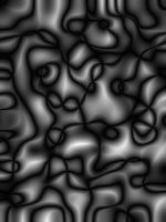
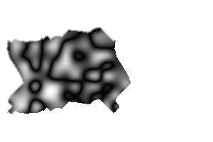
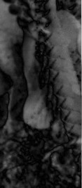
Enough discussion. We will make a tile from this grayscale image:
set SRC=dp_src2.png |
|
Start by finding the four corners.
%IMG7%magick ^ %SRC% ^ -crop 2x1@ +repage ^ -compose Difference -composite ^ dpt_src2_lr.png |
|
|
Which column is darkest? for /F "usebackq delims=, " %%X in (`%IM7DEV%magick ^ dpt_src2_lr.png ^ -scale "x1^!" ^ -negate ^ -process onelightest ^ NULL: 2^>^&1`) do set TIL_X=%%X echo TIL_X=%TIL_X% TIL_X=12 |
[No image] |
We similarly find Y:
for /F "usebackq tokens=2 delims=, " %%Y in (`%IM7DEV%magick ^
  %SRC% ^
  -crop 1x2@ +repage ^
  -compose Difference -composite ^
  +write dpt_src2_tb.png ^
  -scale "1x^!" ^
  -negate ^
  -process onelightest ^
  NULL: 2^>^&1`) do set TIL_Y=%%Y

echo TIL_Y=%TIL_Y%
TIL_Y=57
Now we know the x-y coordinates of the top-left corner of the tile. We readily calculate the coordinates of the other corners by adding half the width and height.
set X0=%TIL_X%
set Y0=%TIL_Y%

for /F "usebackq" %%L in (`%IMG7%magick identify ^
  -format "WW=%%w\nHH=%%h\nX1=%%[fx:int(%X0%+w/2+0.5)]\nY1=%%[fx:int(%Y0%+h/2+0.5)]" ^
  %SRC%`) do set %%L

echo WW=%WW% HH=%HH% X0=%X0% Y0=%Y0% X1=%X1% Y1=%Y1%
WW=300 HH=200 X0=12 Y0=57 X1=162 Y1=157
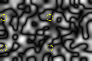
Just for fun, we show these on the image:
%IMG7%magick ^ %SRC% ^ -stroke Yellow -fill None ^ -draw "translate %X0%,%Y0% circle 0,0 0,10" ^ -draw "translate %X0%,%Y1% circle 0,0 0,10" ^ -draw "translate %X1%,%Y0% circle 0,0 0,10" ^ -draw "translate %X1%,%Y1% circle 0,0 0,10" ^ dpt_src2_4cn.png |
|
Now we want the darkest paths that pass through these points, both vertically and horizontally. We do this with super-white gates on the difference images. A file format that can record HDRI must be used.
|
Put a super-white gate at the two vertical positions. call %PICTBAT%supWhGate ^ dpt_src2_lr.png %X0% %Y0% dpt_src2_lr_swg.miff call %PICTBAT%supWhGate ^ dpt_src2_lr_swg.miff %X0% %Y1% dpt_src2_lr_swg.miff |
[No image] |
|
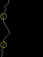
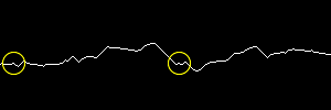
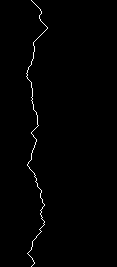
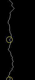
Find the darkest path that passes through the gates. %IM7DEV%magick ^ dpt_src2_lr_swg.miff ^ -process 'darkestpath' ^ +write dpt_src2_lr_swg_ln.png ^ -stroke Yellow -fill None ^ -draw "translate %X0%,%Y0% circle 0,0 0,10" ^ -draw "translate %X0%,%Y1% circle 0,0 0,10" ^ dpt_src2_lr_swg_mp.png |

|
I use darkestpath. Wouldn't darkestmeander give a closer colour match? Yes it would, because darkestmeander can create paths at more than 45° from the intended direction or even do a U-turn if that creates a darker overall path. But this is also a problem as the vertical and horizontal paths could then cross at more than one point, which would make the tiles overlap each other. With darkestpath, this can not happen.
Now we have the left and right edges of the tile. To find the top and bottom edges, we need to rotate the difference image and adjust the XY values accordingly.
%IM7DEV%magick ^
  %SRC% ^
  -crop 1x2@ +repage ^
  -compose Difference -composite ^
  -rotate -90 ^
  dpt_src2_tb.png

set X0R=%Y0%
set /A Y0R=%WW%-%X1%-1
set /A Y1R=%WW%-%X0%-1

echo X0R=%X0R% Y0R=%Y0R% Y1R=%Y1R%
X0R=57 Y0R=137 Y1R=287 |

|
|
Put a super-white gate at the two (rotated) horizontal positions. call %PICTBAT%supWhGate ^ dpt_src2_tb.png ^ %X0R% %Y0R% ^ dpt_src2_tb_swg.miff call %PICTBAT%supWhGate ^ dpt_src2_tb_swg.miff ^ %X0R% %Y1R% ^ dpt_src2_tb_swg.miff |
[No image] |
|
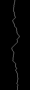
Find the darkest path that passes through the gates. %IM7DEV%magick ^ dpt_src2_tb_swg.miff ^ -process 'darkestpath' ^ +write dpt_src2_tb_swg_ln.png ^ -stroke Yellow -fill None ^ -draw "translate %X0R%,%Y0R% circle 0,0 0,10" ^ -draw "translate %X0R%,%Y1R% circle 0,0 0,10" ^ -rotate 90 ^ dpt_src2_tb_swg_mp.png |
|
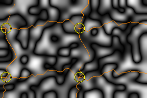
A visual check:
%IMG7%magick ^ ( dpt_src2_lr_swg_mp.png ( +clone ) +append +repage ) ^ ( dpt_src2_tb_swg_mp.png ( +clone ) -append +repage ) ^ -compose Lighten -composite ^ -fill #f80 -opaque White ^ -transparent Black ^ %SRC% ^ -compose DstOver -composite ^ dpt_chk_swg_mp.png |
|
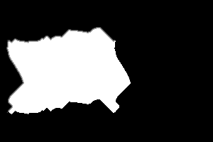
From the two line images _swg_ln.png, we make a mask. We use morphology to slightly extend the mask top and left edges, with a fade. This reduces the sharp boundary we would get where tiled images don't match colours exactly.
The following assumes we can turn all pixels to the left of the white line by flood-filling from 0,0. In real life we can't assume this, and should turn flood-fill from all black pixels in column 0, or do the equivalent with morphology. The script uses either flood-fill or morphology.
|
Make the mask. set DIST_KNL=Euclidean:7
set PIX_OUT=2
%IMG7%magick ^
-fill White ^
( dpt_src2_lr_swg_ln.png ^
-draw "color 0,0 floodfill" ^
( +clone ^
-morphology Distance "%DIST_KNL%,%PIX_OUT%^!" ^
-alpha off ^
-negate ^
) ^
+swap +append +repage ^
) ^
( dpt_src2_tb_swg_ln.png ^
-rotate 90 ^
-draw "color 0,0 floodfill" ^
( +clone ^
-morphology Distance "%DIST_KNL%,%PIX_OUT%^!" ^
-alpha off ^
-negate ^
) ^
+swap -append +repage ^
) ^
-compose Multiply -composite ^
dpt_src2_mask.png
|
|
|
Show the source, masked. This is a single tile. %IM7DEV%magick ^ -fill None ^ %SRC% ^ dpt_src2_mask.png ^ -alpha off ^ -compose CopyOpacity -composite ^ dpt_src2_mskd.png |

|
|
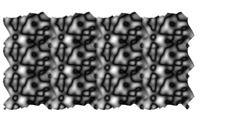
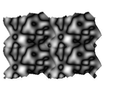
Show more tiles: %IMG7%magick ^ dpt_src2_mskd.png ^ -background None ^ -duplicate 3 ^ -set page +%%[fx:t*w/2]+0 ^ -layers merge ^ -duplicate 2 ^ -set page +0+%%[fx:t*h/2] ^ -layers merge ^ +repage ^ dpt_src2_dup.png |
|
The left-right boundary is very good. The top-bottom boundary isn't quite as good.
The script tileDp.bat implements the above. From an image, it creates a tile that is half the width and height.
For convenience, we set up an environment variable with the IM operations to assemble four tiles.
set TILE_IT=^
  -background None ^
  -duplicate 1 ^
  -set page +%%[fx:t*w/2]+0 ^
  -layers merge ^
  -duplicate 1 ^
  -set page +0+%%[fx:t*h/2] ^
  -background White ^
  -layers merge ^
  +repage
call %PICTBAT%tileDp %SRC% dpt_scr1.png %IMG7%magick ^ dpt_scr1.png ^ %TILE_IT% ^ dpt_scr1_dup.png |
|
The script returns some environment variables:
set tdp
tdpOUTFILE=dpt_scr1.png
tdpX0=12
tdpX1=162
tdpY0=57
tdpY1=157
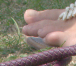
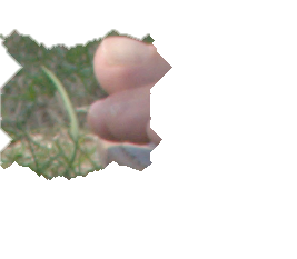
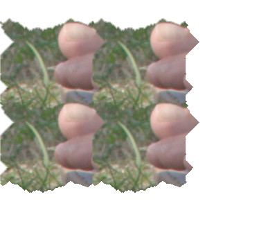
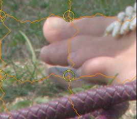
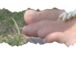
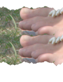
call %PICTBAT%tileDp ^
  toes.png dpt_toes_ex.png

%IMG7%magick ^
  dpt_toes_ex.png ^
  %TILE_IT% ^
  dpt_toes_ex_dup.png
Left-right is poor because no column in the left half
|
|
|
Debug mode creates some extra images. set tdpDEBUG=1 set tdpPREF=dpt_dbg_ call %PICTBAT%tileDp ^ toes.png dpt_toes_dbg.png set tdpPREF= set tdpDEBUG= |
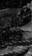
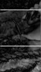

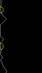


|
|
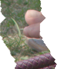
Don't tile horizontally; do tile vertically. call %PICTBAT%tileDp ^ toes.png dpt_toes_v.png 0 1 %IMG7%magick ^ dpt_toes_v.png ^ -duplicate 1 ^ -set page +0+%%[fx:t*h/2] ^ -background White ^ -layers merge ^ dpt_toes_v_dup.png |
|
|
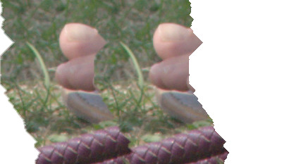
Do tile horizontally; don't tile vertically. call %PICTBAT%tileDp ^ toes.png dpt_toes_h.png 1 0 %IMG7%magick ^ dpt_toes_h.png ^ -duplicate 1 ^ -set page +%%[fx:t*w/2]+0 ^ -background White ^ -layers merge ^ dpt_toes_h_dup.png |
|
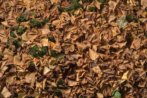
The next example works on a photo about 7000x5000 pixels. The results are resized for the web.
For such large photos, the default process is very slow. The main problem is in tileDp.bat, "-morphology dilate:-1 2x1+1+0:1,1", which turns white any pixels to the left of a white pixel.
So we use an alternative method. This method does a flood-fill from (0,0), as shown above. This won't work properly if column zero contains any white pixels above any black pixels, or if the white line doesn't extend completely from the image top to bottom.
|
The full-size image, shown reduced for the web. set WEB_SIZE=-resize 600x400 set SRC_LVS=%PICTLIB%20151026\AGA_2680_sRGB.tiff %IMG7%magick ^ %SRC_LVS% ^ %WEB_SIZE% ^ dpt_lvs_sm.jpg |
|
|
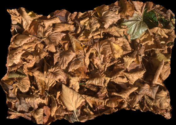
Make the tile. Show it at reduced size for the web. set tdpFTH_SIZ= call %PICTBAT%tileDp %SRC_LVS% dpt_lvs_tile.tiff . . flood set tdpFTH_SIZ= %IMG7%magick ^ dpt_lvs_tile.tiff ^ -trim +repage ^ %WEB_SIZE% ^ dpt_lvs_tile_sm.jpg |
|
|
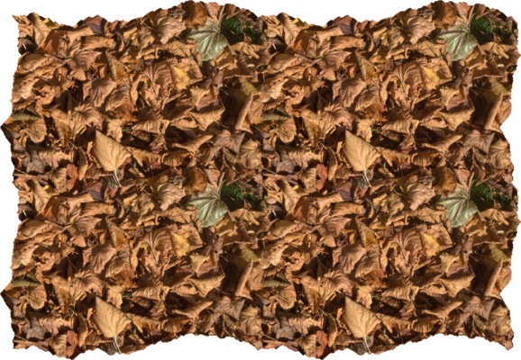
Assemble four tiles. Show the result at reduced size for the web. %IMG7%magick ^ dpt_lvs_tile.tiff ^ %TILE_IT% ^ +write dpt_lvs_tiled4.tiff ^ -trim +repage ^ %WEB_SIZE% ^ dpt_lvs_tiled4_sm.jpg |
|
|
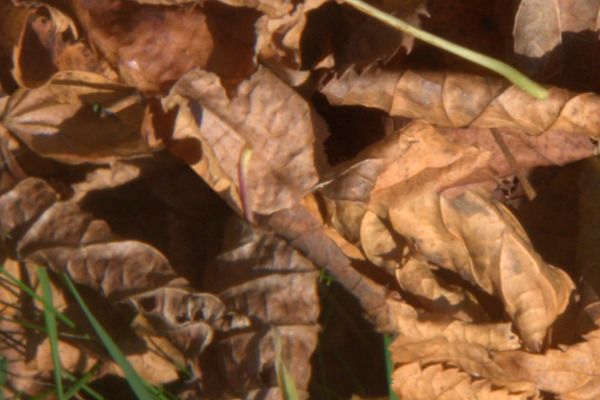
Show the centre of the full-size image at 1:1,
set /A DX=%tdpX1%-300
set /A DY=%tdpY1%-200

echo tdpX1=%tdpX1% tdpY1=%tdpY1% DX=%DX% DY=%DY%

%IMG7%magick ^
  dpt_lvs_tiled4.tiff ^
  -crop 600x400+%DX%+%DY% +repage ^
  dpt_lvs_1_1.jpg
tdpX1=6916 tdpY1=3183 DX=6616 DY=2983 The joins are not easy to identify. |
|
General comments:
The cut lines may not be optimal. For example, we found the least-error column when the left and right sides aligned, but perhaps a smaller least-error column could be found if one image was shifted right or left. This would result in a tile that wasn't exactly half the width of the input image but would have a better colour match when the edges were joined.
Another sub-optimal issue is that we find the least-error column by finding the mean of the columns in their entirety, when we are only really interested in the columns of pixels between the horizontal cuts. Similarly, we are only interested in the least-error of the pixel rows between the vertical cuts. We could find the four points, re-calculate the least-error columns only between the upper and lower points and similarly for the rows. This gives four new points, and we iterate.
Can we make a pyramid, make a tile from each grid, and collapse that? The new pyramid would have transparency.
For convenience, .bat scripts are also available in a single zip file. See Zipped BAT files.
rem From image %1, make tile half width and height by darkest path method.
rem Output is same width and height as input, but only 1/4 of the pixels are opaque.
rem %2 is optional output file.
@rem
@rem %3 whether to make cuts to tile horizontally [1] (vertical cuts)
@rem %4 whether to make cuts to tile vertically [1] (horizontal cuts)
@rem %5 method for whitening, either "morph" (accurate) or "flood" (fast). Default: morph.
@rem   Beware: "flood" assumes (0,0) is black, etc.
@rem
@rem Also uses:
@rem
@rem   tdpFTH_SIZ feathering size for top and left. 0=no feathering [2]
@rem   tdpPREF prefix for working files (not output file).
@rem   tdpDEBUG if 1, also creates debugging images.
@rem
@rem Updated:
@rem   14-July-2022 for IM v7. Added %5.
@rem

@if "%1"=="" findstr /B "rem @rem" %~f0 & exit /B 1

@setlocal enabledelayedexpansion

@call echoOffSave

call %PICTBAT%setInOut %1 tdp


if not "%2"=="" set OUTFILE=%2

set DO_H=%3
if "%DO_H%"=="." set DO_H=
if "%DO_H%"=="" set DO_H=1

set DO_V=%4
if "%DO_V%"=="." set DO_V=
if "%DO_V%"=="" set DO_V=1

set DO_BOTH=0
if %DO_H%==1 if %DO_V%==1 set DO_BOTH=1

set WH_METH=%5
if "%WH_METH%"=="." set WH_METH=
if "%WH_METH%"=="" set WH_METH=morph

if /I %WH_METH%==morph (
  set sWhMeth=-morphology dilate:-1 2x1+1+0:1,1
) else if /I %WH_METH%==flood (
  set sWhMeth=-draw "color 0,0 floodfill"
) else (
  echo %0: Bad WH_METH [%WH_METH%]
  exit /B 1
)

if "%tdpFTH_SIZ%"=="" set tdpFTH_SIZ=2

echo DO_H=%DO_H% DO_V=%DO_V% DO_BOTH=%DO_BOTH%

if "%tdpPREF%"=="" set tdpPREF=tdp_
set EXT=.miff

set X0=0
set Y0=0

if %DO_H%==1 (
echo %0: find TIL_X
for /F "usebackq delims=, " %%X in (`%IM7DEV%magick ^
  %INFILE% ^
  ^( -clone 0 ^
    -colorspace Gray ^
    -crop 2x1@ +repage ^
    -compose Difference -composite ^
    +write %tdpPREF%lr%EXT% ^
    -scale "x1^!" ^
    -negate ^
    -process onelightest ^
    +delete ^
  ^) ^
  NULL: 2^>^&1`) do (
    set TIL_X=%%X
    set X0=%%X
  )
)

if %DO_V%==1 (
echo %0: find TIL_Y
for /F "usebackq tokens=1 delims=, " %%Y in (`%IM7DEV%magick ^
  %INFILE% ^
  ^( -clone 0 ^
    -colorspace Gray ^
    -crop 1x2@ +repage ^
    -compose Difference -composite ^
    -rotate -90 ^
    +write %tdpPREF%tb%EXT% ^
    -scale "x1^!" ^
    -negate ^
    -process onelightest ^
    +delete ^
  ^) ^
  NULL: 2^>^&1`) do (
    set TIL_Y=%%Y
    set Y0=%%Y
  )
)


::test
%IMG7%magick identify ^
  -format "WW=%%w\nHH=%%h\nX1=%%[fx:int(%X0%+w/2+0.5)]\nY1=%%[fx:int(%Y0%+h/2+0.5)]\n" ^
  %INFILE%

if ERRORLEVEL 1 exit /B 1

for /F "usebackq" %%L in (`%IMG7%magick identify ^
  -format "WW=%%w\nHH=%%h\nX1=%%[fx:int(%X0%+w/2+0.5)]\nY1=%%[fx:int(%Y0%+h/2+0.5)]\n" ^
  %INFILE%`) do set %%L

echo WW=%WW% HH=%HH% X0=%X0% Y0=%Y0% X1=%X1% Y1=%Y1%


if %DO_H%==1 (
  echo %0: find vertical path
  rem call %PICTBAT%supWhGate ^
  rem   %tdpPREF%lr%EXT% %X0% %Y0% %tdpPREF%lr_swg.miff
  rem
  rem call %PICTBAT%supWhGate ^
  rem   %tdpPREF%lr_swg.miff %X0% %Y1% %tdpPREF%lr_swg.miff

  call :WhGates %tdpPREF%lr%EXT% !X0! !Y0! !Y1! %tdpPREF%lr_swg.miff

  if ERRORLEVEL 1 exit /B 1

  if "%tdpDEBUG%"=="1" (
    set sWR_LR_MP=-stroke Yellow -fill None ^
      -draw "translate %X0%,%Y0% circle 0,0 0,10" ^
      -draw "translate %X0%,%Y1% circle 0,0 0,10" ^
      %tdpPREF%lr_swg_mp%EXT%

  ) else (
    set sWR_LR_MP=NULL:
  )

  %IM7DEV%magick ^
    %tdpPREF%lr_swg.miff ^
    -process 'darkestpath' ^
    +write %tdpPREF%lr_swg_ln%EXT% ^
    !sWR_LR_MP!
)

if %DO_V%==1 (
  echo %0: find horizontal path
  set X0R=%Y0%
  set /A Y0R=%WW%-%X1%-1
  set /A Y1R=%WW%-%X0%-1

  echo X0R=!X0R! Y0R=!Y0R! Y1R=!Y1R!

  rem call %PICTBAT%supWhGate ^
  rem   %tdpPREF%tb%EXT% ^
  rem   !X0R! !Y0R! ^
  rem   %tdpPREF%tb_swg.miff
  rem
  rem call %PICTBAT%supWhGate ^
  rem   %tdpPREF%tb_swg.miff ^
  rem   !X0R! !Y1R! ^
  rem   %tdpPREF%tb_swg.miff

  call :WhGates %tdpPREF%tb%EXT% !X0R! !Y0R! !Y1R! %tdpPREF%tb_swg.miff

  if "%tdpDEBUG%"=="1" (
    set sWR_TB_MP=-stroke Yellow -fill None ^
      -draw "translate !X0R!,!Y0R! circle 0,0 0,10" ^
      -draw "translate !X0R!,!Y1R! circle 0,0 0,10" ^
      %tdpPREF%tb_swg_mp%EXT%
  ) else (
    set sWR_TB_MP=NULL:
  )

  %IM7DEV%magick ^
    %tdpPREF%tb_swg.miff ^
    -process 'darkestpath' ^
    +write %tdpPREF%tb_swg_ln%EXT% ^
    !sWR_TB_MP!
)

rem Check:
echo %0: check
if %DO_BOTH%==1 if "%tdpDEBUG%"=="1" %IMG7%magick ^
  ( %tdpPREF%lr_swg_mp%EXT% ( +clone ) +append +repage ) ^
  ( %tdpPREF%tb_swg_mp%EXT% ( +clone ) +append +repage -rotate 90 ) ^
  -compose Lighten -composite ^
  -fill #f80 -opaque White ^
  -transparent Black ^
  %INFILE% ^
  -compose DstOver -composite ^
  %tdpPREF%chk_swg_mp%EXT%

set DIST_KNL=Euclidean:7

if "%tdpFTH_SIZ%"=="0" (
  set sFEATH=
) else (
  set sFEATH=-morphology Distance "%DIST_KNL%,%tdpFTH_SIZ%^^^!"
)

echo tdpFTH_SIZ=%tdpFTH_SIZ% sFEATH=%sFEATH%

echo %0: make mask
if %DO_BOTH%==1 (
  %IMG7%magick ^
    -fill White ^
    ^( %tdpPREF%lr_swg_ln%EXT% ^
       %sWhMeth% ^
       -alpha off ^
       ^( +clone ^
          %sFEATH% ^
          -negate ^
       ^) ^
       +swap +append +repage ^
    ^) ^
    ^( %tdpPREF%tb_swg_ln%EXT% ^
       %sWhMeth% ^
       -alpha off ^
       -rotate 90 ^
       ^( +clone ^
          %sFEATH% ^
          -negate ^
       ^) ^
       +swap -append +repage ^
    ^) ^
    -compose Multiply -composite ^
    %tdpPREF%mask%EXT%
  if ERRORLEVEL 1 exit /B 1

) else if %DO_H%==1 (
  %IMG7%magick ^
    -fill White ^
    ^( %tdpPREF%lr_swg_ln%EXT% ^
       %sWhMeth% ^
       -alpha off ^
       ^( +clone ^
          %sFEATH% ^
          -negate ^
       ^) ^
       +swap +append +repage ^
    ^) ^
    %tdpPREF%mask%EXT%
  if ERRORLEVEL 1 exit /B 1

) else if %DO_V%==1 (
  %IMG7%magick ^
    -fill White ^
    ^( %tdpPREF%tb_swg_ln%EXT% ^
       %sWhMeth% ^
      -alpha off ^
      -rotate 90 ^
      ^( +clone ^
         %sFEATH% ^
         -negate ^
      ^) ^
      +swap -append +repage ^
    ^) ^
    %tdpPREF%mask%EXT%
  if ERRORLEVEL 1 exit /B 1
)


echo %0: make tile
%IM7DEV%magick ^
  -fill None ^
  %INFILE% ^
  %tdpPREF%mask%EXT% ^
  -alpha off ^
  -compose CopyOpacity -composite ^
  %OUTFILE%

call echoRestore

endlocal & set tdpOUTFILE=%OUTFILE%& set tdpX0=%X0%& set tdpY0=%Y0%& set tdpX1=%X1%& set tdpY1=%Y1%

exit /B 0

:: ------------- Subroutines -------------

:: %1 input image
:: %2 X
:: %3 Y0
:: %4 Y1
:: %5 output file
:: Assumes WW

:WhGates

echo %0: %1 %2 %3 %4 %5

::test
%IMG7%magick identify ^
  -format "Wm1=%%[fx:%WW%-1]\nXm1=%%[fx:%2-1]\nXp1=%%[fx:%2+1]\nHasL=%%[fx:%2>0?1:0]\nHasR=%%[fx:%2<%WW%-1?1:0]\n" ^
  %INFILE%

if ERRORLEVEL 1 exit /B 1

for /F "usebackq" %%L in (`%IMG7%magick identify ^
  -format "Wm1=%%[fx:%WW%-1]\nXm1=%%[fx:%2-1]\nXp1=%%[fx:%2+1]\nHasL=%%[fx:%2>0?1:0]\nHasR=%%[fx:%2<%WW%-1?1:0]\n" ^
  %INFILE%`) do set %%L

if !HasL!==0 (
  set DrawL1=
  set DrawL2=
) else (
  set DrawL1=-draw "line 0,%3 !Xm1!,%3"
  set DrawL2=-draw "line 0,%4 !Xm1!,%4"
)

echo %0: DrawL1=%DrawL1%
echo %0: DrawL2=%DrawL2%

if !HasR!==0 (
  set DrawR1=
  set DrawR2=
) else (
  set DrawR1=-draw "line !Xp1!,%3 !Wm1!,%3"
  set DrawR2=-draw "line !Xp1!,%4 !Wm1!,%4"
)

echo %0: DrawR1=%DrawR1%
echo %0: DrawR2=%DrawR2%

%IM7DEV%magick ^
  %1 ^
  -stroke rgb(100000%%,100000%%,100000%%) ^
  !DrawL1! ^
  !DrawR1! ^
  !DrawL2! ^
  !DrawR2! ^
  -define quantum:format=floating-point ^
  %5

if ERRORLEVEL 1 exit /B 1

exit /B 0
All images on this page were created by the commands shown, using:
%IMG7%magick -version
Version: ImageMagick 7.1.0-42 Q16-HDRI x64 396d87c:20220709 https://imagemagick.org
Copyright: (C) 1999 ImageMagick Studio LLC
License: https://imagemagick.org/script/license.php
Features: Cipher DPC HDRI OpenCL
Delegates (built-in): bzlib cairo freetype gslib heic jng jp2 jpeg jxl lcms lqr lzma openexr pangocairo png ps raqm raw rsvg tiff webp xml zip zlib
Compiler: Visual Studio 2022 (193231332)
%IM7DEV%magick -version
Version: ImageMagick 7.1.0-20 Q32-HDRI x86_64 2021-12-29 https://imagemagick.org
Copyright: (C) 1999-2021 ImageMagick Studio LLC
License: https://imagemagick.org/script/license.php
Features: Cipher DPC HDRI Modules OpenMP(4.5)
Delegates (built-in): bzlib cairo fontconfig fpx freetype jbig jng jpeg lcms ltdl lzma pangocairo png raqm rsvg tiff webp wmf x xml zip zlib
Compiler: gcc (11.2)
Source file for this web page is dptile.h1. To re-create this web page, execute "procH1 dptile".
This page, including the images, is my copyright. Anyone is permitted to use or adapt any of the code, scripts or images for any purpose, including commercial use.
Anyone is permitted to re-publish this page, but only for non-commercial use.
Anyone is permitted to link to this page, including for commercial use.
Page version v1.0 27-Oct-2015.
Page created 25-Aug-2022 21:22:01.
Copyright © 2022 Alan Gibson.