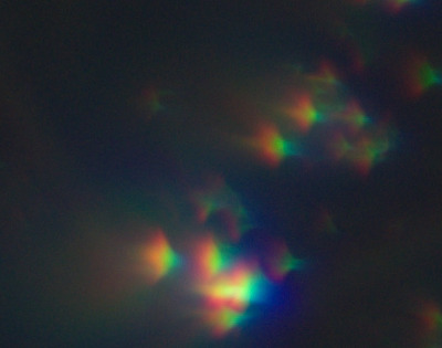
A single-element lens bends light (refraction), with the intention that rays from a distant object hitting different parts of the lens are focused on a single point on the sensor. The amount of bending depends on the colour of the light, and on the glass used (its index of refraction, IoR, which varies according to wavelength). Blue light bends more than red light. So if white light passes through a single-element lens the red, green and blue components will bend by different amounts, and hence will focus at different places. This is chromatic aberration (CA).
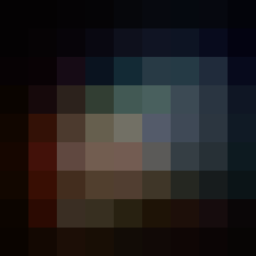
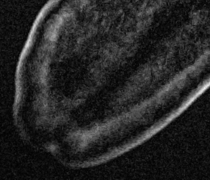
Crop from the left side of photo taken with single-element lens (185mm f/4.3),
showing chromatic, comatic and other aberrations.
A different colour may focus at a different distance from the lens (axial CA, aka longitudinal CA) or a different distance from the centre of the sensor (transverse CA, aka lateral CA), or both. The distances depend on the lens aperture but also on the distance of the light source from the plane that is in focus.
In film photography, CA is difficult to correct in post. In digital photography, transverse CA can be reduced by a geometrical distortion of the red, green and blue components of the image.
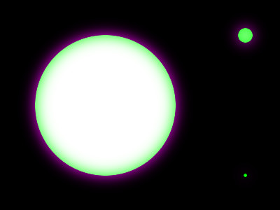
Camera lenses reduce CA by using multiple elements with different IoRs. But the problem can't be entirely removed. It is one of the many trade-offs that a lens designer has to make.
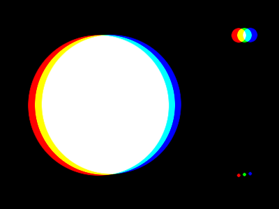
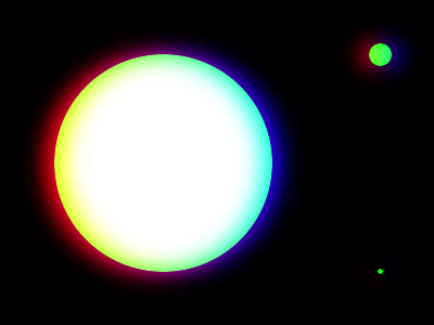
The problem shows as false colours at high-contrast edges. It is most noticable at edges furthest from the image centre.
Axial CA:
is worse at long focal lengths;
is reduced at small apertures;
is difficult to correct.
Transverse CA:
is worse at short focal lengths;
is not affected by aperture;
shows as red and green fringing on opposite sides of light patches on dark backgrounds (or dark patches on light background);
is quite easy to correct.
set SRCNEF=%PICTLIB%20120918\DSC_0314.NEF

%DCRAW% -6 -T -w -O cf_1.tiff %SRCNEF%

set CaW=9
set CaH=9
set CaX=54
set CaY=4881

set sCROP=-crop %CaW%x%CaH%+%CaX%+%CaY% +repage

set sPROC=-strip %sCROP% -scale 4000%%
But does it need fixing? On many images, the effect of CA is not noticable, and fixing it doesn't improve the image. Sometimes CA adds interest to an image. It can be treated like any photographic quality just like depth of field or slow shutter speeds or anything else. So leaving CA alone is always an option.
But sometimes we do want to fix it.
Possible solutions include:
Proprietary software from the lens manufacturer or elsewhere.
The Lensfun database or software or both, or software that uses Lensfun.
General-purpose software such as ImageMagick.
The manufacturer should be in the best position to know the characteristics of a lens, including tolerances, and is in the best position to know how to correct aberrations. But manufacturers don't publish these details, so we have a blunt choice of using their software or not.
As a first approximation, we model chromatic aberration as a geometric distortion of two channels with respect to the third. In theory this will fix transverse CA, but not axial CA. By convention we distort the red and blue channels to align with the green channel.
We assume the distortion that corrects the aberration is a radial movement towards or away from the centre. (More strictly, towards or away the optical axis, the location on the sensor where the lens axis intersects.) We assume circular symmetry, so the distortion is independent of the polar angle.
rd = f(ru)
... where ru is the undistorted normalised radius, rd is the distorted radius, and f() is a function that is zero at zero radius, and otherwise returns a value for rd that is close to ru. "Normalised" means the radius is one at the centre of the long sides. (Beware: other definitions of "normalised" can be used.) A polynomial is one such function:
rd = a*ru4 + b*ru3 + c*ru2 + d*ru
This is the same formula that is sometimes used to correct barrel/pincushion distortion. Effectively, we are correcting barrel/pincushion distortion in two channels with respect to the third.
If d is close to one and the other coefficients are close to zero, rd will be close to ru.
If we require that at ru=1, there is no resizing so rd=1 (the radius is unchanged at r==1) then:
a + b + c + d = 1
For overall barrel/pincushion distortion, some software will default d = 1-(a+b+c), and some software will always use this value for d without allowing the user to change it.
There will be one set of coefficients for the red channel, and a different set of coefficients for the blue channel.
We assume the only non-zero coefficient is d, so the transformation is:
rd = d*ru
This is a simple resizing.
Blah get the multipliers. Resize image with those parameters, or feed back to dcraw.
Use linear input?
The script
chromAberr.bat finds scaling factors for the red and blue channels that make them most closely match the green channel within a defined crop area. It is fast and gives a good result for that area and other areas at a similar radius from the centre. But it might make CA worse at other radii.
The script
caResize.bat applies these resizing factors to the red and green channels with ImageMagick's -distort SRT. We crop and enlarge to see the effect:
As expected, the result for this cropped area is good. We could extend the analysis to sample multiple areas to obtain a resizing that was optimised for the entire image. If we sampled four or more areas, we could use simultaneous equations to obtain the abcd parameters for a barrel/pincushion distortion of the red and blue channels.
We can directly use the two resizing factors as parameters to the dcraw -C option:
The result is similar to the caResize.bat result, but they are not identical. In dcraw.c, the function scale_colors() uses simple bilinear interpolation between four input pixels. IM's -distort SRT uses higher-quality EWA resampling.
The Hugin toolset includes tca_correct.exe that samples locations of an image to find the barrel/pincushion distortion to make the red and blue channels align with the green channel.
The Hugin equation for barrel/pincushion distortion works in the opposite direction to IM. [Is it???] The Hugin equation is:
rdest = a*rsrc4 + b*rsrc3 + c*rsrc2 + d*rsrc
Questions: where is r=1? Which way round are r parameters?
According to
Lens correction model, r=1 for the largest circle that fits in the image, so r=1 at a distance half the smallest side from the centre.
In tca_correct.exe, the four parameters are named a, b, c and v. We can optimize all four of these...
for /F "usebackq tokens=*" %%L in (`%HUG%tca_correct ^
  -o abcv ^
  cf_1.tiff`) do set TCA_CORR1=%%L

echo TCA_CORR1=%TCA_CORR1%
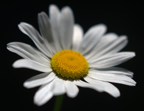
Axial CA causes different frequencies of light from an object to focus at different distances from the lens. When an object is out of focus, a light ray will not be focused on the sensor; it will be spread across an area. Different frequencies of light focus at different distances, so they spread to varying degrees across the sensor. The effect is most noticable when the object has low saturation.
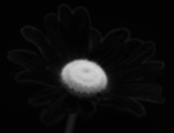
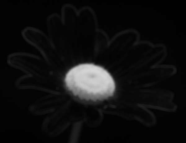
For example, a close-up of a white flower against a nearly black background:
set FLOWER_SRC=%PICTLIB%\20180611\AGA_3690_sRGB.tiff
set CROP_FLOWER=-crop 3196x2450+1916+1483
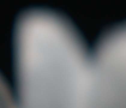
set CROP_FAR=-crop 420x360+2951+1547
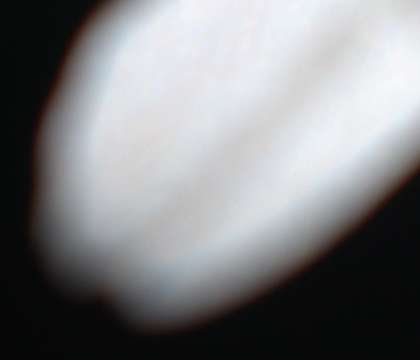
set CROP_NEAR=-crop 420x360+2621+3500
set WEB_SIZE=-resize 600x600
The white petals beyond the plane of focus have a blue fringe, and those in front of the plane of focus have a red fringe. The fringes are slight, and perhaps they add aesthetic quality by increasing the impression of depth (because blue tends to sink behind the frame, while red tends to pop out.)
The full image somewhat cropped, and resized for the web.
ASIDE: What causes the blue fringe for objects beyond the plane of focus, and the red fringe for objects closer than the plane of focus?
We can draw diagrams showing red, green and blue rays from a white object, assuming the lens bends blue light more than red, and that this causes axial CA but not transverse CA. The diagrams show cross-sections (not to scale), with the object off-diagram to the left, rays travelling to the right, being refracted by the lens, converging towards the sensor.
For each colour, we show rays that pass through two parts of the lens. Where the two rays of a colour intersect, that colour is in focus.
First, the far-side situation:
When the object is beyond the plane of focus, blue and green light come to focus in front of the sensor, with the blue focus furthest in front.
Hence the blue light has spread most when it reaches the sensor, the green light spreads less, and red light spreads least (and may not spread at all, meaning it is in focus, as shown here).
And now the near-side situation:
When the object is closer to the camera than the plane of focus, green and red light would come to focus behind the sensor, with the red focus furthest behind.
Hence the red light has converged the least (it is most out of focus) and green light has converged more, and blue light has converged the most (it may be exactly in focus, as shown here).
So, different wavelengths are smeared by different amounts, and this causes a blue fringe for objects beyond the plane of focus, and red fringing for objects nearer than the plane of focus.
The amount of smearing depends on the distance between the object and plane of focus, and the aperture, and the radial distance from the image centre. Ordinary cameras do not record distances of all objects in a scene, and deriving this from a single image is non-trivial. So determining how much smearing has occured is difficult, and correcting it is virtually impossible.
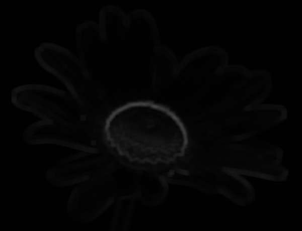
A pragmatic solution is to cap the chroma (or saturation), for example to the mean chroma plus the chroma standard deviation multiplied by a factor ...
C' = min (C, meanC + k * sdC)
... where mean and SD are windowed, defined over the same area.
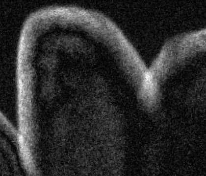
We show the chroma as grayscale, lighter where the chroma is greater. We auto-level the 1:1 crops to more easily see where we have chroma.
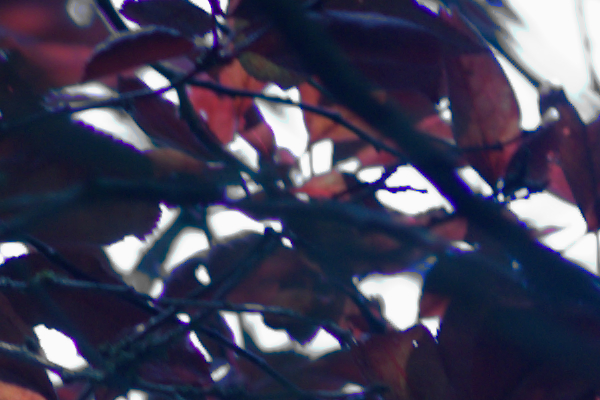
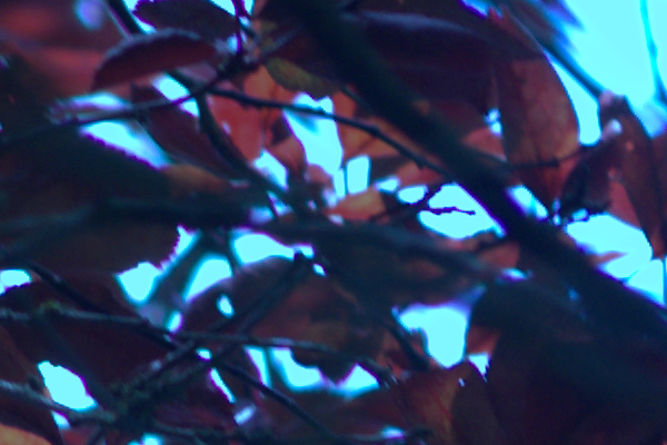
A tree with red leaves is back-lit by a blue sky. In this shot, the blue sky is over-exposed to almost pure white. Where the reddish leaves or branches are out of focus, they blend with the sky. This reduces the light from the sky sufficiently that the red channel is not clipped, but the green and blue channels are clipped, so the result is cyan.
The script
deColLab.bat reduces the saturation of coloured pixels, either wherever they occur (all) or only where they occur as fringes (fringe). It does this by compositing a desaturated image over the input, masked where we want the desaturation. To identify colourness, it operates in L*a*b* space, possibly ignoring the L* channel. (HCL could be used instead, but needs a modulus operation to avoid problems from the discontinuity at red H=0=100%.) This "_colmsk" mask is white where the input is exactly the specified colour, black where it clearly isn't, or some shade of gray. When the fringe method is used, "_colmsk" is multiplied by "_frng" mask that is white where a pixel is in the proximity of a close-to-black area and a close-to-white area. The "_frng" mask is blurred to avoid sudden transitions.
By specifying regardL, only pixels close to the lightness percentage are desaturated. This is needed to prevent the darker colours in the leaves and branches from being affected. As each step removes only a narrow range of colours, we need many steps.
call %PICTBAT%deColLab ^
  cf_bb1.png cf_tmp.miff all regardL "96,45,47"
if ERRORLEVEL 1 goto error

call %PICTBAT%deColLab ^
  cf_tmp.miff cf_tmp.miff all regardL "91,31.1,44.5"
if ERRORLEVEL 1 goto error

call %PICTBAT%deColLab ^
  cf_tmp.miff cf_tmp.miff all regardL "81,37,39"
if ERRORLEVEL 1 goto error

call %PICTBAT%deColLab ^
  cf_tmp.miff cf_tmp.miff all regardL "70,42,39"
if ERRORLEVEL 1 goto error

call %PICTBAT%deColLab ^
  cf_tmp.miff cf_tmp.miff all regardL "60,49,29"
if ERRORLEVEL 1 goto error

call %PICTBAT%deColLab ^
  cf_tmp.miff cf_tmp.miff all regardL "56,45,45"
if ERRORLEVEL 1 goto error

call %PICTBAT%deColLab ^
  cf_tmp.miff cf_tmp.miff all regardL "52,64,23"
if ERRORLEVEL 1 goto error

call %PICTBAT%deColLab ^
  cf_tmp.miff cf_bb1_nb.png all regardL "42,48,36"
if ERRORLEVEL 1 goto error
A more elegant method would be:
Create an image containing just the colours that are to be desaturated, eg a gradient from very light cyan to medium cyan (see
Gradients beween two colours).
Remap the input to the output from (1).
Get the difference between the input and the output from (2).
Process as above, using the output from (3) instead of the "_colmsk" mask.
ASIDE: My goal is usually to create an image as an end-product. If the goal is a scene-referred image, then clipped pixels could be replaced by a gradient that represents the blue sky, with those values recorded in HDRI beyond 100%.
Purple fringes can occur at fairly sharp boundaries between fairly light and dark areas. On a Nikon D800, they seem to be worse at large apertures, and most noticable when sky is visible through foliage (possibly proportional to the amount of UV light). The effect seems more pronounced in less expensive cameras, possibly due to smaller sensor size (ie greater pixel density, more sensors per millimetre).
To me, purple fringes are most objectionable when they form a high-saturation boundary between light and dark areas of low saturation.
The script
dePurp.bat reduces the saturation of purple fringes. It does this by compositing a desaturated image over the input, masked where we want the desaturation. To identify purpleness, it operates in L*a*b* space, ignoring the L* channel. (HCL could be used instead, as purple is distant enough from the discontinuity at red H=0=100%.) This "_purp" mask is white where the input is exactly purple, black where it clearly isn't, or some shade of gray. This is multiplied by a mask "_frng" that is white where a pixel is in the proximity of a close-to-black area and a close-to-white area. The "_frng" mask is blurred to avoid sudden transitions.
:skip

call %PICTBAT%dePurp ^
  cf_bb1.png ^
  cf_bb1_dp.png ^
  all
If the subject happens to have a genuine purple fringe between light and dark areas, the script will desaturate it. So the script should be used with caution.
Future: instead of desaturating the fringes (which makes then gray), it might look better (and be more technically correct) if we changed the colour to be an average of surrounding pixels. This could be done by making the pixels transparent, then blur-filling them.
rem From image %1
rem crop parameters %2 to %5
rem calculates chromatic aberration parameters by trial and error
rem setting environment variables prefixed with %6.
@rem
@rem Updated:
@rem   10-August-2022 for IM v7.
@rem

@if "%1"=="" findstr /B "rem @rem" %~f0 & exit /B 1

@setlocal enabledelayedexpansion

@call echoOffSave


set INFILE=%1

set CaW=%2
if "%CaW%"=="." set CaW=
if "%CaW%"=="" set CaW=w

set CaH=%3
if "%CaH%"=="." set CaH=
if "%CaH%"=="" set CaH=h

set CaX=%4
if "%CaX%"=="." set CaX=
if "%CaX%"=="" set CaX=0

set CaY=%5
if "%CaY%"=="." set CaY=
if "%CaY%"=="" set CaY=0

set ENVPREF=%6
if "%ENVPREF%"=="." set ENVPREF=
if "%ENVPREF%"=="" set ENVPREF=cab__

for /F "usebackq" %%L in (`%IMG7%magick identify ^
  -format "WW=%%w\nHH=%%h\nHalfSht=%%[fx:min(w,h)/2]\nCaDX=%%[fx:(w/2-%CaX%-%CaW%/2)]\nCaDY=%%[fx:(h/2-%CaY%-%CaH%/2)]\n" ^
  %INFILE%`) do set %%L

for /F "usebackq" %%L in (`%IMG7%magick identify ^
  -format "CaRad=%%[fx:hypot(2*%CaDX%/%WW%,2*%CaDY%/%HH%)]\n" ^
  xc:`) do set %%L

for /F "usebackq" %%L in (`%IMG7%magick identify ^
  -format "CaRad=%%[fx:hypot(%CaDX%/%WW%,%CaDY%/%HH%)/%HalfSht%]\n" ^
  xc:`) do set %%L

for /F "usebackq" %%L in (`%IMG7%magick identify ^
  -format "CaRad=%%[fx:2*hypot(%CaDX%,%CaDY%)/hypot(%WW%,%HH%)]\n" ^
  xc:`) do set %%L

for /F "usebackq" %%L in (`%IMG7%magick identify ^
  -format "PorM=%%[fx:hypot(%CaW%,%CaH%)/hypot(%CaDX%,%CaDY%)/4]\n" ^
  xc:`) do set %%L

for /F "usebackq" %%L in (`%IMG7%magick identify ^
  -format "F1=%%[fx:1-%PorM%]\nF2=%%[fx:1+%PorM%]\n" ^
  xc:`) do set %%L

set sCROP=-crop %CaW%x%CaH%+%CaX%+%CaY% +repage

set sPROC=-strip %sCROP% -scale 5000%%

set TMPPREF=\temp\ch_
set TMPEXT=miff

%IMG7%magick ^
  %INFILE% ^
  -strip %sCROP% -separate ^
  +adjoin ^
  %TMPPREF%_%%d.%TMPEXT%

rem echo WW=%WW% HH=%HH% CaDX=%CaDX% CaDY=%CaDY% CaRad=%CaRad%

call %PICTBAT%whatScaleT2 ^
  %TMPPREF%_0.%TMPEXT% ^
  %TMPPREF%_1.%TMPEXT% ^
  %F1% %F2% %CaDX% %CaDY%

if ERRORLEVEL 1 exit /B 1

set ScaleR=%wstSCALE%

call %PICTBAT%whatScaleT2 ^
  %TMPPREF%_2.%TMPEXT% ^
  %TMPPREF%_1.%TMPEXT% ^
  %F1% %F2% %CaDX% %CaDY%

if ERRORLEVEL 1 exit /B 1

set ScaleB=%wstSCALE%


call echoRestore

endlocal & set %ENVPREF%_CaRad=%CaRad%& set %ENVPREF%_ScaleR=%ScaleR%& set %ENVPREF%_ScaleB=%ScaleB%
rem From image %1
rem makes output %2
rem %3 scale factor for red channel
rem %4 scale factor for blue channel


@if "%1"=="" findstr /B "rem @rem" %~f0 & exit /B 1

@setlocal enabledelayedexpansion

@call echoOffSave

call %PICTBAT%setInOut %1 car

if not "%2"=="" if not "%2"=="." set OUTFILE=%2

set ScaleR=%3
if "%ScaleR%"=="." set ScaleR=
if "%ScaleR%"=="" set ScaleR=1

set ScaleB=%4
if "%ScaleB%"=="." set ScaleB=
if "%ScaleB%"=="" set ScaleB=1

%IMG7%magick ^
  %INFILE% ^
  -channel RGB ^
  -separate ^
  +channel ^
  ( -clone 0 ^
    -distort SRT %ScaleR%,0 ) ^
  -swap 0,3 +delete ^
  ( -clone 2 ^
    -distort SRT %ScaleB%,0 ) ^
  +swap +delete ^
  -combine ^
  %OUTFILE%

call echoRestore

endlocal & set carOUTFILE=%OUTFILE%
@rem Given same-size images %1 and %2,
@rem finds scale S in "-distort SRT S,0" for %1 to best match %2, and a score.
@rem
@rem Parameters:
@rem   %3 min scale (default 0.5)
@rem   %4 max scale (default 1.5)
@rem   %5 CX } Centre for scaling
@rem   %6 CY }
@rem
@rem Updated:
@rem   10-August-2022 for IM v7.
@rem

@rem Unlike whatScale.bat,
@rem this works by brute force trial-and-error of the entire images.
@rem So this may be more suitable when not much of either image is in focus.


@if "%2"=="" findstr /B "rem @rem" %~f0 & exit /B 1

@setlocal enabledelayedexpansion

@call echoOffSave


if "%wstMETRIC%"=="" set wstMETRIC=RMSE

set wstMIN_SCALE=%3
if "%wstMIN_SCALE%"=="." set wstMIN_SCALE=
if "%wstMIN_SCALE%"=="" set wstMIN_SCALE=0.5

set wstMAX_SCALE=%4
if "%wstMAX_SCALE%"=="." set wstMAX_SCALE=
if "%wstMAX_SCALE%"=="" set wstMAX_SCALE=1.5

if "%wstMIN_SCALE%"=="" exit /B 1

set CX=%5
if "%CX%"=="." set CX=
if "%CX%"=="" set CX=0

set CY=%6
if "%CY%"=="." set CY=
if "%CY%"=="" set CY=0

echo CX=%CX%  CY=%CY%

set PRECISION=%wstPRECISION%
if "%PRECISION%"=="" set PRECISION=-precision 6

set TMPEXT=.miff
set TMPDIR=%TEMP%

call %PICTBAT%setInOut %1 wst
set IN_A=%INFILE%
set IN_A_TMP=%TMPDIR%\%~n1_wst_inA%TMPEXT%
set IN_A_ONE=%TMPDIR%\%~n1_wst_oneA%TMPEXT%

call %PICTBAT%setInOut %2 wst
set IN_B=%INFILE%
set IN_B_TMP=%TMPDIR%\%~n2_wst_inB%TMPEXT%
set IN_B_ONE=%TMPDIR%\%~n2_wst_oneB%TMPEXT%

set DEBUG_FILE=wst_%~n1_%~n2_dbg%EXT%

echo IN_A=%IN_A%  IN_B=%IN_B%

if "%~x1"=="%TMPEXT%" (
  set IN_A_TMP=%IN_A%
) else (
  %IMG7%magick %IN_A% %IN_A_TMP%

  if ERRORLEVEL 1 exit /B 1
)

if "%~x2"=="%TMPEXT%" (
  set IN_B_TMP=%IN_B%
) else (
  %IMG7%magick %IN_B% %IN_B_TMP%

  if ERRORLEVEL 1 exit /B 1
)

for /F "usebackq" %%L ^
in (`%IMG7%magick identify ^
  -precision 16 ^
  -format "WW1=%%w\nHH1=%%h\nInvCX=%%[fx:-(%CX%)]\nInvCY=%%[fx:-(%CY%)]" ^
  %IN_A_TMP%`) ^
do set %%L

if "%WW1%"=="" exit /B 1

echo InvCX=%InvCX%  InvCY=%InvCY%

%IMG7%magick convert ^
  %IN_A_TMP% ^
  -distort SRT %CX%,%CY%,1,0 ^
  %IN_A_ONE%

%IMG7%magick convert ^
  %IN_B_TMP% ^
  -distort SRT %CX%,%CY%,1,0 ^
  %IN_B_ONE%

set SCALE0=%wstMIN_SCALE%
set SCALE1=0
set SCALE2=0
set SCALE3=%wstMAX_SCALE%

set A_SCALE=%TMPDIR%\%~n1_wst_A_S%TMPEXT%
set B_SCALE=%TMPDIR%\%~n2_wst_B_S%TMPEXT%


call :TryScale %SCALE0%
set COMP0=!COMP!

call :TryScale %SCALE3%
set COMP3=!COMP!

set nIter=0
set FINISHED=0


:loop

if %SCALE0%==%SCALE2% set FINISHED=1

for /F "usebackq" %%L ^
in (`%IMG7%magick identify %PRECISION% ^
  -precision 16 ^
  -format "SCALE1=%%[fx:%SCALE0%*pow(%SCALE3%/%SCALE0%,1/3)]\nSCALE2=%%[fx:%SCALE0%*pow(%SCALE3%/%SCALE0%,2/3)]" ^
  xc:`) ^
do set %%L

if %SCALE0%==%SCALE1% set FINISHED=1
if %SCALE1%==%SCALE2% set FINISHED=1
if %SCALE2%==%SCALE3% set FINISHED=1

call :TryScale %SCALE1%
set COMP1=!COMP!

call :TryScale %SCALE2%
set COMP2=!COMP!

echo Scale: %SCALE0% %SCALE1% %SCALE2% %SCALE3%
echo Comp: %COMP0% %COMP1% %COMP2% %COMP3%

for /F "usebackq" %%L ^
in (`%IMG7%magick identify ^
  -format "High0=%%[fx:%COMP0%>%COMP3%?1:0]\nHigh3=%%[fx:%COMP0%<%COMP3%?1:0]" ^
  xc:`) ^
do set %%L

if %High0%==1 (
  set SCALE0=%SCALE1%
  set COMP0=%COMP1%
) else if %High3%==1 (
  set SCALE3=%SCALE2%
  set COMP3=%COMP2%
) else (
  set FINISHED=1
)

set /A nIter+=1

if %FINISHED%==0 goto loop

echo nIter=%nIter%

call echoRestore

endlocal & set wstSCALE=%SCALE1%& set wstCOMP=%COMP1%

exit /B 0


rem -------------------------------------
rem Subroutines

:TryScale
set SC=%1

for /F "usebackq" %%L ^
in (`%IMG7%magick identify ^
  -precision 16 ^
  -format "Gtr1=%%[fx:%SC%>1?1:0]\nInvSc=%%[fx:1.0/%SC%]" ^
  xc:`) ^
do set %%L

if %Gtr1%==1 (

  %IMG7%magick ^
    %IN_A_TMP% ^
    -distort SRT %CX%,%CY%,%SC%,0 ^
    %A_SCALE%

  for /F "tokens=2 usebackq delims=() " %%L ^
in (`%IMG7%magick compare ^
  %A_SCALE% ^
  %IN_B_ONE% ^
  -metric %wstMETRIC% ^
  NULL: 2^>^&1`) ^
do set COMP=%%L

) else (
  %IMG7%magick ^
    %IN_B_TMP% ^
    -distort SRT %CX%,%CY%,%InvSc%,0 ^
    %B_SCALE%

  for /F "tokens=2 usebackq delims=() " %%L ^
in (`%IMG7%magick compare ^
  %IN_A_ONE% ^
  %B_SCALE% ^
  -metric %wstMETRIC% ^
  NULL: 2^>^&1`) ^
do set COMP=%%L

)
exit /B 0
rem From image %1,
rem makes output %2
rem using transverse chromatic aberration (TCA) parameters %3
rem as created by Hugin tca_correct.exe, probably quoted.
@rem
@rem Updated:
@rem   8-August-2022 for IM v7.
@rem

@if "%1"=="" findstr /B "rem @rem" %~f0 & exit /B 1

@setlocal enabledelayedexpansion

@call echoOffSave

call %PICTBAT%setInOut %1 tcac

if not "%2"=="" if not "%2"=="." set OUTFILE=%2

set PARAMS=%~3

for /F "tokens=1-10 delims=: " %%A in ("%PARAMS%") do (
  if not "%%A"=="-r" exit /B 1
  if not "%%F"=="-b" exit /B 1
  set ar=%%B
  set br=%%C
  set cr=%%D
  set dr=%%E
  set ab=%%G
  set bb=%%H
  set cb=%%I
  set db=%%J
)

for /F "usebackq" %%L in (`%IMG7%magick identify ^
  -format "sumr=%%[fx:%ar%+(%br%)+(%cr%)+(%dr%)]\nsumb=%%[fx:%ab%+(%bb%)+(%cb%)+(%db%)]\n" ^
  xc:`) do set %%L

echo sumr=%sumr% sumb=%sumb%

%IMG7%magick ^
  %INFILE% ^
  -channel RGB ^
  -separate ^
  +channel ^
  -verbose ^
  ( -clone 0 ^
    -distort BarrelInverse %ar%,%br%,%cr%,%dr% ) ^
  -swap 0,3 +delete ^
  ( -clone 2 ^
    -distort BarrelInverse %ab%,%bb%,%cb%,%db% ) ^
  +verbose ^
  +swap +delete ^
  -combine ^
  %OUTFILE%

call echoRestore

endlocal & set tcacOUTFILE=%OUTFILE%
rem From image %1,
rem makes output %2
rem with lowered saturation at coloured fringes.
rem %3 is method:
rem   all    desaturate all coloured pixels
rem   fringe desaturate only coloured pixels that are
rem          within a few pixels of both nearly black
rem          and nearly white
rem default: fringe
rem %4: "regardL" or "ignoreL"
rem %5 percentage values for L*,a*,b* for the colour
rem    Format either "srgb(12.34%,23.45%,34.56%)"
rem    or "12.34,23.45,34.56".
@rem
@rem
@rem
@rem Also uses:
@rem   DP_DBG_PREF if set, prefix for debug files.
@rem     (Default: make no debug files.)
@rem   DP_DBG_EXT if set, extension for debug files.
@rem     (Default: "miff".)
@rem
@rem Reference:
@rem   http://im.snibgo.com/colfring.htm
@rem
@rem Updated:
@rem   10-August-2022 for IM v7.
@rem


@if "%1"=="" findstr /B "rem @rem" %~f0 & exit /B 1

@setlocal enabledelayedexpansion

@call echoOffSave

call %PICTBAT%setInOut %1 dcl

if not "%2"=="" if not "%2"=="." set OUTFILE=%2

set METHOD=%3
if "%METHOD%"=="." set METHOD=
if "%METHOD%"=="" set METHOD=fringe

set doL=%4
if "%doL%"=="." set doL=
if "%doL%"=="" set doL=ignoreL

set VALS=%~5
if "%VALS%"=="." set VALS=
if "%VALS%"=="" set VALS=50,50,50

set START=%VALS:~0,4%
if /I "%START%"=="srgb" (
  set COL="%VALS%"
) else (
  call parseCommaList "%VALS%" dcl_argc dcl_argv

  if not !dcl_argc!==3 (
    echo VALS needs 3 comma-separated numbers "%VALS%"
    exit /B 1
  )

  set COL=sRGB(!dcl_argv[0]!%%,!dcl_argv[1]!%%,!dcl_argv[2]!%%)
)

echo COL=[%COL%]

if /I %METHOD%==all (
  set ENDFIRST=mpr:GRAY ^
    +swap ^
    -compose Over -composite ^
    %OUTFILE%
) else if /I %METHOD%==fringe (
  set ENDFIRST=NULL:
) else (
  echo %0: Unknown method [%METHOD%]
  exit /B 1
)

if /I %doL%==regardL (
  set setL=
) else if /I %doL%==ignoreL (
  set setL=-channel R -evaluate set 50%% +channel
) else (
  echo %0: Unknown doL [%doL%]
  exit /B 1
)


set TMPDIR=\temp\
set TMPEXT=miff
set TMPPREF=%TMPDIR%dcl_%~n1

if "%DP_DBG_EXT%"=="" set DP_DBG_EXT=miff

%IMG7%magick ^
  %INFILE% ^
  ( +clone ^
    -colorspace Lab ^
    -set colorspace sRGB ^
    ( +clone ^
      -channel R -separate +channel ^
      +write mpr:GRAY ^
      +write %TMPPREF%_gray.%TMPEXT% ^
      +delete ^
    ) ^
    %setL% ^
    ( +clone ^
      -fill %COL% ^
      -colorize 100 ^
    ) ^
    -compose Difference -composite ^
    -grayscale RMS ^
    -level 10,5%% ^
    +write %TMPPREF%_colmsk.%TMPEXT% ^
  ) ^
  %ENDFIRST%

if ERRORLEVEL 1 exit /B 1

if /I %METHOD%==fringe %IMG7%magick ^
  %INFILE% ^
  ( %TMPPREF%_gray.%TMPEXT% +write mpr:GRAY ) ^
  ( ^
    ( mpr:GRAY ^
      ( -clone 0 ^
        -threshold 15%% -blur 0x3 -fill Black +opaque White ^
        -negate ^
        +write %TMPPREF%_t0.%TMPEXT% ^
      ) ^
      ( -clone 0 ^
        -threshold 70%% -blur 0x3 -fill White +opaque Black ^
        +write %TMPPREF%_t1.%TMPEXT% ^
      ) ^
      -delete 0 ^
      -compose Darken -composite ^
      -blur 0x2 ^
      +write %TMPPREF%_frng.%TMPEXT% ^
    ) ^
    %TMPPREF%_colmsk.%TMPEXT% ^
    -compose Multiply -composite ^
    +write %TMPPREF%_cfmsk.%TMPEXT% ^
  ) ^
  -compose Over -composite ^
  %OUTFILE%

call echoRestore

endlocal & set dclOUTFILE=%OUTFILE%
tca_correct version 2020.0.0.2f576e5d5b4a built by Thomas
To improve internet download speeds, some images may have been automatically converted (by ImageMagick, of course) from PNG or TIFF or MIFF to JPG.
Source file for this web page is colfring.h1. To re-create this web page, execute "procH1 colfring".
This page, including the images, is my copyright. Anyone is permitted to use or adapt any of the code, scripts or images for any purpose, including commercial use.
Anyone is permitted to re-publish this page, but only for non-commercial use.
Anyone is permitted to link to this page, including for commercial use.