set WIDTH=300 set HEIGHT=200 %IMG7%magick ^ -size %WIDTH%x%HEIGHT% ^ gradient: ^ gr_baseGrad.png

This page is mostly about two-dimensional greyscale gradients, ranging from black to white, that have different values for both x and y dimensons. They are useful as masks for processing photographs, for video transitions, and a variety of graphics effects.
I use ImageMagick gradients as masks for processing photographs and for video transitions. Gradients are usually monochrome images with smooth transitions from black through gray to white.
For one-dimensional gradients, see Clut cookbook.
The scripts are all Windows "bat" syntax, and readily translatable to other languages.
The environment variable %IMG7% is set to the directory that contains the IM magick program.
The dimensions of the mask are generally taken from the photograph or video frame:
FOR /F "tokens=1,2" %%i ^
IN ('%IMG%magick identify -ping -format "%%w %%h" photo.jpg') ^
DO (
  set WIDTH=%%i
  set HEIGHT=%%j
)
... or ...
FOR /F "usebackq" %%L IN (`%IMG7%magick identify -ping -format "WIDTH=%%w\nHEIGHT=%%h" %SRC%`) DO set %%L
Masks are used to blend still photographs, such as two versions of one image, with different saturations:
%IMG7%magick ^
  {photo1} ^
  {photo2} ^
  {mask} ^
  -alpha off ^
  -compose ^
  {outphoto}
... or ...
%IMG7%magick ^
  {photo1} ^
  ( {photo2} {mask} -alpha off -compose Copy-Opacity -composite ) ^
  -compose Over -composite ^
  {outphoto}
Where the mask is black, Copy-Opacity makes the result transparent, so photo1 becomes visible. Where the mask is white the result is opaque, so photo2 is visible.
For videos, using clippings option TransitionMask, we modulate the influence of the mask over time:
%IMG7%magick ^
  {clip1_frame} ^
  ( {clip2_frame} ^
    ( {mask} -alpha off -level %lev1%x%lev2%%% ) ^
    -compose Copy_Opacity -composite ^
  ) ^
  -compose Over -composite ^
  {outclip_frame}
... where 0 <= lev1 <= lev2 <= 100.
The above command is equivalent to:
%IMG7%magick ^
  {clip2_frame} ^
  ( {mask} -alpha off -level %lev1%x%lev2%%% ) ^
  -compose Copy_Opacity -composite ^
  {clip1_frame} ^
  -compose Dst_Over -composite ^
  {outclip_frame}
The basic gradient is white at the top, black at the bottom:
set WIDTH=300 set HEIGHT=200 %IMG7%magick ^ -size %WIDTH%x%HEIGHT% ^ gradient: ^ gr_baseGrad.png |
|
50% gray occurs at the position mid-way between black and white. Similarly for all percentages. So thresholding at x% results in x% of pixels being black, and modulating a video threshold at a constant speed results in a constant speed of transition.
For a sideways transition, we rotate, so we need to invert the initial width and height.
%IMG7%magick ^ -size %HEIGHT%x%WIDTH% ^ gradient: ^ -rotate 90 ^ gr_baseGradS.png |

|
This is used for a basic left-to-right transition:
%IMG7%magick ^ -size %WIDTH%x%HEIGHT% ^ xc:Red ^ xc:Green ^ ( gr_baseGradS.png -level 20%%x30%% ) ^ -composite ^ gr_baseEx.png |

|
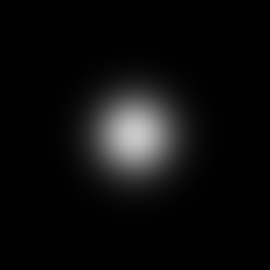
A radial-gradient transitions from the centre outwards.
%IMG7%magick ^ -size %WIDTH%x%HEIGHT% ^ radial-gradient: ^ gr_rad.png |

|
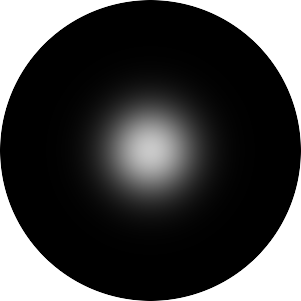
Note that "radial-gradient:" applies only to max(width,height) from the image centre. To fade all the way to the corners, start with a square image that is as wide as the diagonal we want. The contours of the gradient are circular.
FOR /F %%i ^
IN ('%IMG7%magick identify ^
  -format "%%[fx:int(sqrt(%WIDTH%*%WIDTH%+%HEIGHT%*%HEIGHT%)+0.5)]" ^
  xc:') ^
DO set DIM=%%i

%IMG7%magick ^
  -size %DIM%x%DIM% ^
  radial-gradient: ^
  -gravity Center -crop %WIDTH%x%HEIGHT%+0+0 +repage ^
  gr_rad2.png
|

|
A related gradient has equal values at the centre of each edge, so the contours are elliptical.
FOR /F %%i ^
IN ('%IMG7%magick identify ^
  -format "%%[fx:max(%WIDTH%,%HEIGHT%)]" ^
  xc:') ^
DO set MAX=%%i

FOR /F %%i ^
IN ('%IMG7%magick identify ^
  -format "%%[fx:int(%MAX%*sqrt(2)+0.5)]" ^
  xc:') ^
DO set DIM=%%i

%IMG7%magick ^
  -size %DIM%x%DIM% ^
  radial-gradient: ^
  -gravity Center -crop %MAX%x%MAX%+0+0 +repage ^
  -resize "%WIDTH%x%HEIGHT%^!" ^
  gr_rad3.png
|

|
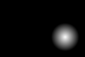
We can create a radial gradient of diameter 100, on a larger image, centering the gradient at (230,130). The parameter to "-extent" is WxH-X-Y where (X,Y) is the required coordinate of the top-left of the image so far. So X = 230-100/2 = 180 and Y = 130-100/2 = 80.
%IMG7%magick ^ -size 100x100 ^ radial-gradient: ^ -background #000 ^ -extent %WIDTH%x%HEIGHT%-180-80 ^ gr_rad4.png |
|
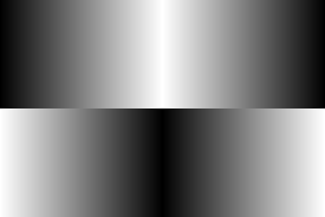
We can readily chop and rearrange masks:
%IMG7%magick ^ gr_baseGrad.png ^ -crop 2x1@ ^ ( -clone 0 -negate ) ^ -delete 0 ^ +append +repage ^ gr_baseGrad2.png |

|
%IMG7%magick ^ gr_baseGradS.png ^ -crop 1x2@ ^ ( -clone 0 -negate ) ^ -delete 0 ^ -append +repage ^ gr_baseGradS2.png |

|
%IMG7%magick ^ gr_baseGradS2.png ^ ( +clone -negate )^ +append +repage ^ -resize "%WIDTH%x%HEIGHT%^!" ^ gr_baseGradS4.png |
|
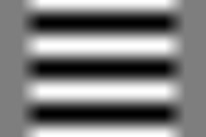
set NUM=3 set ANG=90 %IMG7%magick ^ -size %WIDTH%x%HEIGHT% ^ gradient: ^ -function Sinusoid %NUM%,%ANG%,0.5,0.5 ^ gr_sinus.png |

|
set NUM=3 set ANG=90 %IMG7%magick ^ -size %WIDTH%x%HEIGHT% ^ xc: ^ -sparse-color barycentric "0,0 gray80 %%[fx:w-1],%%[fx:h-1] gray20" ^ -function Sinusoid %NUM%,%ANG%,0.5,0.5 ^ -function Sinusoid %NUM%,%ANG%,0.5,0.5 ^ gr_sinus2.png |

|
%IMG7%magick ^ gr_baseGradS.png ^ ( +clone -negate ) ^ +append +repage ^ -resize "%WIDTH%x%HEIGHT%^!" ^ -depth 16 ^ gr_barnDoor.png |

|
%IMG7%magick ^
  gr_sinus.png ^
  ( gr_barnDoor.png -level 20%%,40%% ) ^
  -compose CopyOpacity -composite ^
  -write gr_sb.png ^
  -background Gray -alpha Remove ^
  gr_sinusBd.png
This might be useful for a shimmy effect, where pixels are displaced to left or right. |
|
We can quantise (this one calls for a sound FX of a cell-door slamming at each transition). This is also useful for checking that a complex gradient is equally spaced, or that it proceeds in a straight line.
%IMG7%magick ^ gr_baseGradS2.png ^ +dither -posterize 10 ^ gr_baseQ.png |

|
The patches at each end are smaller because "-posterize" uses gray levels of 0%, 11.1%, 22.2% etc, so levels of 0 to 5.5% go into the first band, where the second band takes levels of 5.5% to 16.6%.
If we want ten levels of the same width from black to white, we can use a trick from the Clut Cookbook:
%IMG7%magick ^
  gr_baseGradS2.png ^
  ( -size 1x256 gradient: -rotate 90 ^
    -fx "int(u*10)/9" ^
  ) ^
  -interpolate NearestNeighbor ^
  -clut ^
  gr_baseQ2.png
|

|
The script could be simpler, by applying "-fx" directly to the source file istead of via a clut. But that would be slower: one "-fx" per source pixel insted of one per clut pixel, and a clut is (usually) much smaller than source files.
"-interpolate NearestNeighbor" ensures that every pixel is one of the ten levels, avoiding any interpolation at a boundary. However, boundary interpolation (aka anti-aliasing) may be preferred.
Or, more simply, we can use "-colors". But this doesn't give us ten colours. It merely guarantees there will be ten colours or fewer.
%IMG7%magick ^ gr_baseGradS2.png ^ +dither -colors 10 ^ gr_baseQ3.png |

|
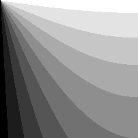
We can bend linear gradients into arcs.
FOR /F %%i ^
IN ('%IMG7%magick identify -format "%%[fx:max(%WIDTH%,%HEIGHT%)/2]" xc:') ^
DO (
  set RMAX=%%i
)

set /A POL_WI=RMAX*3
set /A POL_HT=RMAX
Note we invert the usual height and width, because we will rotate. %IMG7%magick ^ -size %POL_HT%x%POL_WI% ^ gradient: ^ -rotate 90 ^ -distort Arc ^"180 0 %HEIGHT% 0^" ^ +repage ^ gr_arc180Mask.png %IMG7%magick identify gr_arc180Mask.png gr_arc180Mask.png PNG 402x202 402x202+0+0 16-bit Grayscale Gray 95755B 0.000u 0:00.000 |

|
%IMG7%magick ^
  -size %POL_HT%x%POL_WI% ^
  gradient: ^
  -rotate 90 ^
  -distort Arc ^"90 45 %HEIGHT% 0^" ^
  -flip ^
  +repage ^
  gr_arc90Mask.png

%IMG7%magick identify gr_arc90Mask.png
gr_arc90Mask.png PNG 202x202 202x202+0+0 16-bit Grayscale Gray 53482B 0.000u 0:00.000 |

|
%IMG7%magick ^ gr_arc90Mask.png ^ ( +clone -flop ) ^ +append +repage ^ gr_arc902Mask.png |

|
%IMG7%magick ^ gr_arc90Mask.png ^ ( +clone -flop ) ^ +swap ^ +append +repage ^ gr_arc902bMask.png |

|
The "rising curtain" effect, gr_arc902Mask.png, will have straight lines that meet in the centre-line at an angle. This can be seen when we posterize it:
%IMG7%magick ^ gr_arc902Mask.png ^ +dither -posterize 10 ^ gr_arc902MaskQ.png |

|
If we prefer a curved line, we can use a modified version of gr_arc90Mask.png, using an absolute displacement map, displacing only horizontally. The map is of a kind of ripple such that f(0)=0, f'(0)=1, f(1)=1 but f'(1)=1. The first quarter of a sin curve is such a function.
FOR /F "tokens=1,2" %%i ^
IN ('%IMG7%magick identify -ping -format "%%w %%h" gr_arc90Mask.png') ^
DO (
  set wi=%%i
  set ht=%%j
)
We write and display gr_preSin.png merely for comparison with gr_qtrSin.png. %IMG7%magick ^ -size %wi%x%ht% ^ gradient: -rotate 90 ^ -write gr_preSin.png ^ -function sinusoid 0.25,0,1,0 ^ gr_qtrSin.png gr_qtrSin.png is the absolute displacement map |


|
|
Apply the absolute displacement map. %IMG7%magick ^
gr_arc90Mask.png ^
gr_qtrSin.png ^
-fx "p{v*w,j}" ^
gr_arc90qsMask.png
|

|
|
Demonstrate it: %IMG7%magick ^ gr_arc90qsMask.png ^ +dither -posterize 10 ^ gr_arc90qsMaskD.png |
|
gr_qtrSin is used as an absolute displacement mask. IM has no operators to process absolute displacement masks, so we need to use "-fx", which is slow. As we don't do this processing for every frame, speed doesn't matter. If we needed the processing for every frame, we might convert it to a relative displacement mask. See Displacement maps.
With greyRectMask.bat, we can choose the grey levels for the corners:
call %PICTBAT%greyRectMask.bat ^ %WIDTH% %HEIGHT% 75 90 20 30 |

|
A diagonal gradient is simple, eg top-left white to bottom-right black:
%IMG7%magick ^ -size %WIDTH%x%HEIGHT% xc:white ^ -sparse-color barycentric "0,0 white %%[fx:w-1],%%[fx:h-1] Black" ^ gr_diag.png |

|
call %PICTBAT%ellipMaskCornCol.bat ^ %WIDTH% %HEIGHT% 10 10 10 75 75 75 |

|
call %PICTBAT%ellipMaskCorn.bat ^ %WIDTH% %HEIGHT% 10 75 |

|
We can simulate pond ripples. Note that "radial-gradient:" applies only to max(width,height) from the image centre, so we build a square image that is as wide as the diagonal we want.
We can vary ang from zero to 360 for one cycle, or zero to (360 * %NUM%) = (360*3) = 1080 for three cycles, from centre to corner.
set NUM=3
set ANG=90

FOR /F %%i ^
IN ('%IMG7%magick identify ^
  -format "%%[fx:int(sqrt(%WIDTH%*%WIDTH%+%HEIGHT%*%HEIGHT%)+0.5)]" ^
  xc:') ^
DO set DIM=%%i

%IMG7%magick ^
  -size %DIM%x%DIM% ^
  radial-gradient: ^
  -function Sinusoid %NUM%,%ANG%,0.5,0.5 ^
  -gravity Center -crop %WIDTH%x%HEIGHT%+0+0 +repage ^
  gr_pond.png
|
|
The next mask is useful for burning-in (darkening) the bottom edge of a photo, with the effect increasing slightly towards the corners.
call %PICTBAT%baseMask.bat ^ %WIDTH% %HEIGHT% 25 |

|
The resulting height and width will be twice the polar argument RMAX, plus one or two so we should crop the results (not shown here).
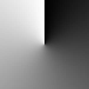
for /F "usebackq" %%i in (`%IMG7%magick identify ^
  -format "%%[fx:max(%WIDTH%,%HEIGHT%)/2]" ^
  xc:`) do set RMAX=%%i

set /A POL_WI=RMAX*3
set /A POL_HT=RMAX

rem Note we invert the usual height and width, because we will rotate.

%IMG7%magick ^
  -size %POL_HT%x%POL_WI% gradient: ^
  -rotate -90 ^
  +distort Polar ^"%RMAX%^" ^
  +repage ^
  gr_clock.png

%IMG7%magick identify -ping -format "%%w %%h" gr_clock.png
302 302 |
|
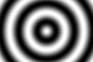
%IMG7%magick -size %POL_HT%x%POL_WI% gradient: ^
  -rotate -90 ^
  +distort Polar ^"%RMAX%,0 0.5,0.5^" ^
  +repage ^
  gr_clock2.png

%IMG7%magick identify -ping -format "%%w %%h" gr_clock2.png
301 301 |
|
%IMG7%magick -size %POL_HT%x%POL_WI% gradient: ^
  -rotate 90 ^
  ( +clone ) ( +clone ) +append +repage ^
  +distort Polar ^"%RMAX%,0 0.5,0.5^" ^
  +repage -flop ^
  gr_clock3.png

%IMG7%magick identify -ping -format "%%w %%h" gr_clock3.png
301 301 |
|
%IMG7%magick -size %POL_HT%x%POL_WI% gradient: ^
  -function Sinusoid 4,90 ^
  -rotate 90 ^
  +distort Polar ^"%RMAX%,0 0.5,0.5^" ^
  +repage -flop ^
  gr_clock4.png

%IMG7%magick identify -ping -format "%%w %%h" gr_clock4.png
301 301 |
|
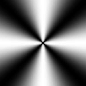
An alternative method for the basic gradient uses "-fx atan2":
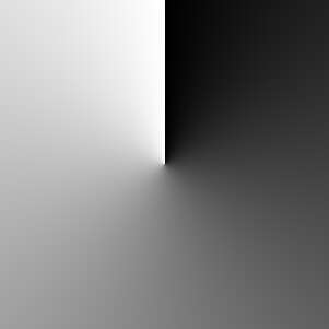
%IMG7%magick ^
  -size %WIDTH%x%WIDTH% gradient: -rotate -90 ^
  ( +clone -rotate -90 ) ^
  +write gr_2grad.png ^
  -fx "atan2(u-0.5,v-0.5)/2/pi+0.5" ^
  gr_clock2b.png

%IMG7%magick ^
  -size %WIDTH%x%WIDTH% gradient: -rotate 180 ^
  ( +clone -rotate -90 ) ^
  +write gr_2grad.png ^
  -fx "atan2(u-0.5,v-0.5)/2/pi+0.5" ^
  -evaluate AddModulus 75%% ^
  gr_clock2b.png

%IMG7%magick identify -ping -format "%%w %%h" gr_clock2b.png
300 300 |
|
Current "-fx" is fast. In old versions of IM (prior to about 7.1.0-20) "-fx" was too slow for large images. An alternative uses -function ArcTan, generalised to find the arctan(x,y) for any pair of input files, is:
rem Note: 1/pi = 0.3183098861837907 rem This needs HDRI. %IM7DEV%magick ^ gr_2grad-0.png gr_2grad-1.png ^ -evaluate Subtract 50%% ^ ( -clone 1 -threshold 0 +write mpr:MASK +delete ) ^ -define compose:clamp=off ^ -compose DivideSrc -composite ^ -function ArcTan 0.3183098861837907,0,0.5,0.5 ^ -write-mask mpr:MASK -evaluate AddModulus 50%% +write-mask ^ -evaluate AddModulus 75%% ^ gr_clock2c.png |

|
The Dst and Src to the divide range from -50% to +50%. The -function ArcTan expression is:
y = range/pi * atan (slope * pi * (u - center)) + bias
  =   0.5/pi * atan (pi/pi *      (u -    0  )) + 0.5
  = 1/(2*pi) * atan(u) + 0.5
atan(u) returns between -pi/2 and +pi/2 radians (-90 and +90 degrees). We multiply by 1/(2*pi) to get a range -0.25 to +0.25, then add 0.5 to get a range +0.25 to +0.75. Where the Src is negative, the answer so far is wrong by pi radians (180 degrees), and we rectify this by adding 0.5 when Src is less than or equal to 0%.
However, when Src==0, DivideSrc returns merely 100%, so the arctan returns 45°, which is wrong. We could special-case this, but it gets a bit messy. Instead, we write a process module: arctan2.
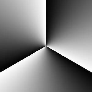
%IM7DEV%magick ^ gr_2grad-0.png gr_2grad-1.png ^ -evaluate Subtract 50%% ^ -process 'arctan2 b 0' ^ -evaluate AddModulus 25%% ^ gr_clock2d.png |
|
We use this process module in the script slopeXYdirn.bat. See "direction" in the Slopes page.
%IMG7%magick ^ gr_2grad-0.png gr_2grad-1.png ^ gr_2grad_tmp.miff call %PICTBAT%slopeXYdirn ^ gr_2grad_tmp.miff ^ gr_clock2e.png ^ . SUB 25 |

|
These can usefully be swirled. The swirl effect doesn't extend beyond the inscribed circle, so it might be wise to create a larger image then crop to within that circle: make the width and height of the square equal to the diagonal of the required image.
%IMG7%magick ^ gr_clock2.png ^ -filter Point -interpolate Integer ^ -swirl 180 ^ gr_clock2s.png |
|
%IMG7%magick ^ gr_clock2.png ^ -filter Point -interpolate Integer ^ -swirl 540 ^ gr_clock2sb.png |
|
%IMG7%magick ^ gr_clock3.png ^ -filter Point -interpolate Integer ^ -swirl 180 ^ gr_clock3s.png |
|
%IMG7%magick ^ gr_clock4.png ^ -filter Point -interpolate Integer ^ -swirl 180 ^ gr_clock4s.png |
|
A different spiral is available by using morphology distance to create the transition. This is somewhat slow.
We create the polygon carefully so it will tile exactly. We want only two colours, so switching off interpolation (+antialias, -filter Point -interpolate Integer) would be good. But this leads to slight weirdness, so we threshold and level.
set wi=300
set ht=300

set /A wim1=%wi%-1
set /A htm1=%ht%-1

set /A swi=%wi%/2
set /A sht=%ht%/2

set /A swip1=%swi%+1

set /A shtm1=%sht%-1
set /A shtm2=%sht%-2

%IMG7%magick ^
  -size %wi%x%ht% ^
  xc:Black ^
  -fill White ^
  -draw ^"polygon 0,0 %wim1%,%htm1% %swi%,%htm1% 0,%shtm1% ^
          polygon %swip1%,0 %wim1%,0 %wim1%,%shtm2%^" ^
  gr_poly.png

  rem -fill rgb(50%%,50%%,50%%) ^
|

|
If we wanted more than a single turn of the spiral, we would append:
%IMG7%magick ^ gr_poly.png ^ ( +clone ) ^ ( +clone ) ^ +append +repage ^ gr_poly3.png |

|
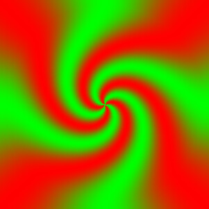
If we just wanted spirals, without the morphology transition, we might want "-virtual-pixel tile" before the distort. But that breaks spiral arms at the edges so morphology can't reach the end segments.
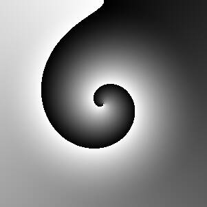
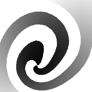
%IMG7%magick ^ gr_poly.png ^ +distort Polar ^"%RMAX%,0 0.5,0.5^" ^ +repage ^ -alpha off ^ gr_spiral.png rem -channel RGB -threshold 25%% +level 0,50%% ^ |
|
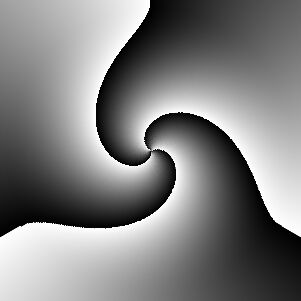
%IMG7%magick ^ gr_spiral.png -rotate 90 ^ gr_spiral.png ^ -compose Difference -composite ^ -write gr_spiral2a.png ^ -channel RGB -threshold 50%% ^ -alpha off ^ gr_spiral2.png |
|
FOR /F "tokens=1,2" %%i ^
IN ('%IMG7%magick identify -ping -format "%%w %%h" gr_spiral2.png') ^
DO (
  set wi=%%i
  set ht=%%j
)

set /A swi=%wi%/2
set /A sht=%ht%/2

rem set /A cxplus=%swi%+5
rem set /A cyplus=%sht%+5
rem set /A cymin=%sht%-5

%IMG7%magick ^
  gr_spiral2.png ^
  -draw "point %swi% %sht%" ^
  -alpha off ^
  gr_spiral2.png

%IMG7%magick ^
  gr_spiral2.png ^
  -negate ^
  -draw "point %swi% %sht%" ^
  -alpha off ^
  gr_spiral2n.png
|
|
The centre of each mask, (swi,sht), must be black so the morphology will straddle both arms. This also provides a good starting point for the morphology.
"Euclidean:2,10": radius 2 isn't noticably worse than 4 or 7. Increment 10 allows for a spiral length of 6553 pixels.
For 2 Mpix (video) images, each morphology takes about 12 minutes. If the spiral was perfectly symmetrical, we could do half of one morphology, and rotate/negate as required.
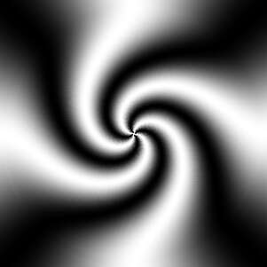
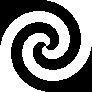
%IMG7%magick ^ -size %wi%x%ht% ^ xc: -draw "point %swi% %sht%" ^ -write-mask gr_spiral2.png ^ -morphology IterativeDistance:-1 Euclidean:2,10 ^ +write-mask ^ -alpha off ^ -fill black -opaque white -auto-level ^ -draw "point %swi% %sht%" ^ gr_spiral4.png |
|
%IMG7%magick ^ -size %wi%x%ht% ^ xc: -draw "point %swi% %sht%" ^ -write-mask gr_spiral2n.png ^ -morphology IterativeDistance:-1 Euclidean:2,10 ^ +write-mask ^ -alpha off ^ -fill black -opaque white -auto-level ^ -transparent Black ^ -draw "point %swi% %sht%" ^ gr_spiral4n.png |
|
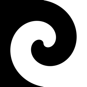
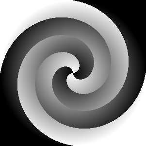
%IMG7%magick ^ ( gr_spiral4.png -negate ) ^ gr_spiral4n.png ^ -composite ^ gr_spiralMask.png |

|
Phew. Got there in the end. If this was a final image, we wouldn't want the aliasing. For a video F/X mask, we do, because otherwise we would get weirdness at the edges.
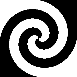
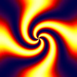
A similar effect is possible, much faster, by compositing the spiral over a radial gradient.
FOR /F "tokens=1,2" %%i ^
IN ('%IMG7%magick identify -ping -format "%%w %%h" gr_spiral2.png') ^
DO (
  set wi=%%i
  set ht=%%j
)

%IMG7%magick ^
  -size %wi%x%wi% ^
  radial-gradient: ^
  gr_spGrad.png

%IMG7%magick ^
  gr_spGrad.png ^
  ( -clone 0 gr_spiral2.png -alpha off ^
    -compose CopyOpacity -composite ^
  ) ^
  ( -clone 0 -negate ^
    ( gr_spiral2.png -negate -alpha off ) ^
    -compose CopyOpacity -composite ^
  ) ^
  -delete 0 ^
  -compose Over -composite ^
  gr_spFast.png
|
|
This mask retains the aspect ratio at all gradations. We create a quarter-mask that can then be appended.
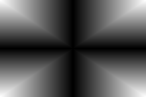
set /A semiWi=%WIDTH%/2 set /A semiHt=%HEIGHT%/2 %IMG7%magick ^ ( -size %semiWi%x%semiHt% gradient: -rotate 180 ) ^ ( -size %semiHt%x%semiWi% gradient: -rotate 90 ) ^ -compose Darken -composite ^ gr_semiMask.png |

|
%IMG7%magick ^ gr_semiMask.png ^ ( +clone -flop ) ^ +append +repage ^ ( +clone -flip ) ^ -append +repage ^ gr_rectMask.png |

|
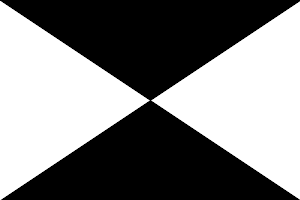
%IMG7%magick ^ ( gr_semiMask.png -rotate 180 ) ^ ( +clone -flop ) ^ +append +repage ^ ( +clone -flip ) ^ -append +repage ^ gr_crossMask.png |
|
%IMG7%magick ^ -size %WIDTH%X%HEIGHT% ^ xc:white ^ -draw ^"polygon %semiWi%,%semiHt% 0,0 %WIDTH%,0 ^" ^ -draw ^"polygon %semiWi%,%semiHt% 0,%HEIGHT% %WIDTH%,%HEIGHT% ^" ^ gr_rectM.png |
|
%IMG7%magick ^ gr_rectMask.png ^ ( +clone -negate gr_rectM.png -alpha off -compose Copy-Opacity ) ^ -compose Over -composite ^ gr_rectNeg.png |

|
|
Swirl can be used, with care. Posterized to show the effect at transitional corners: %IMG7%magick ^ gr_rectMask.png ^ -swirl 90 ^ +dither -posterize 10 ^ gr_rectMaskS.png |

|
Some scripts create gradients:
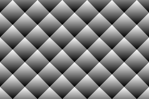
call %PICTBAT%mDiamondMask.bat ^ gr_DiamondMask.png ^ %WIDTH% %HEIGHT% 6 4 |
|
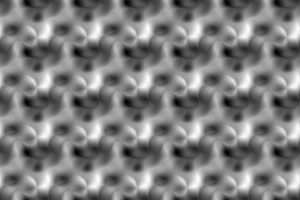
set mbmSEED=1234 call %PICTBAT%mBlobMask.bat ^ gr_blobMask.png ^ %WIDTH% %HEIGHT% 6 4 5 |
|
call %PICTBAT%mBlobMask.bat ^ gr_blobMask2.png ^ %WIDTH% %HEIGHT% |

|
%IMG7%magick ^ gr_blobMask2.png ^ -shade 135x45 ^ -auto-level ^ gr_blobMask3.png set mbmSEED= |

|
Many of the above gradients are (approximately) symmetrical about the centre. This can be changed by suitable cropping, or by a Shepards distortion:
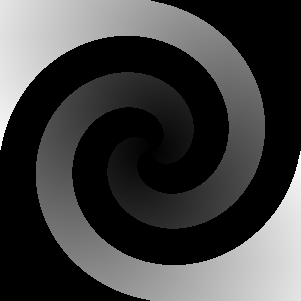
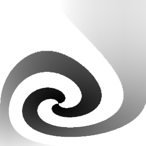
call %PICTBAT%offCentre.bat ^ gr_spiralMask.png -10 21 gr_spiralOc.png ^ -filter Point -interpolate Integer |
|
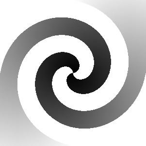
An alternative method is by transforming the red and green channels of an identity displacement map with power curves, and then applying the transformed map.
set ID_ABS_MAP=0,0,#000,^
%%[fx:w-1],0,#f00,^
0,%%[fx:h-1],#0f0,^
%%[fx:w-1],%%[fx:h-1],#ff0

%IMG7%magick ^
  gr_spiralMask.png ^
  -set colorspace sRGB ^
  ( +clone ^
    -sparse-color Bilinear "%ID_ABS_MAP%" ^
    -channel Red   -evaluate Pow %%[fx:log(0.5)/log(0.40)] ^
    -channel Green -evaluate Pow %%[fx:log(0.5)/log(0.71)] ^
    +channel ^
  ) ^
  -compose Distort -composite ^
  gr_spiralOc2.png
|
|
We can do the same transformation more directly with -fx:
set sFX=^
  Wm=%%[fx:w-1]; ^
  Hm=%%[fx:h-1]; ^
  p{ Wm * pow (i/Wm, %%[fx:log(0.5)/log(0.40)] ), ^
     Hm * pow (j/Hm, %%[fx:log(0.5)/log(0.71)] )  ^
   }

%IMG7%magick ^
  gr_spiralMask.png ^
  -fx "%sFX%" ^
  gr_spiralOc3.png
|

|
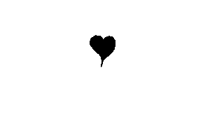
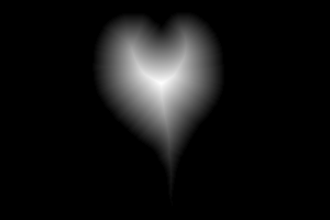
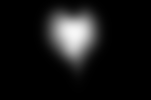
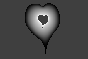
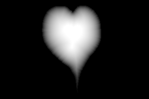
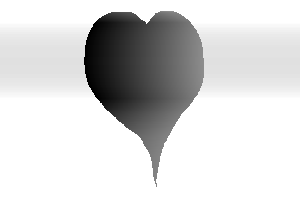
From an arbitrary black-on-white shape, we can create a gradient mask outwards to the image's edges, or white-on-black for a gradient inwards. Then generate the basic gradient by "-morphology Distance".
|
shapeA.png: |
|
FOR /F %%i ^
IN ('%IMG7%magick identify ^
-format "%%[fx:int(QuantumRange/max(w,h)+0.5)]" ^
shapeA.png') ^
DO (
set INC=%%i
)
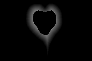
%IMG7%magick ^
shapeA.png ^
-morphology Distance Euclidean:7,%INC% ^
-auto-level ^
-evaluate Multiply 4 ^
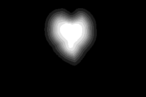
gr_shapeAm.png
rem -evaluate Multiply 2 ^
|

|
|
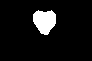
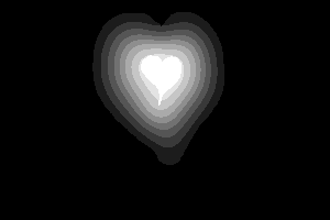
shapeB.png: |

|
FOR /F %%i ^
IN ('%IMG7%magick identify ^
-format "%%[fx:int(QuantumRange/max(w,h)*4+0.5)]" ^
shapeB.png') ^
DO (
set INC=%%i
)
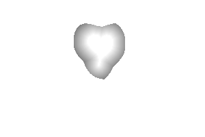
%IMG7%magick ^
shapeB.png ^
-morphology Distance Euclidean:7,%INC% ^
-auto-level ^
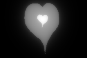
gr_shapeBm.png
|
|
|
Where are the two fades equal? (Not necessarily 50%, or even a constant level.) %IMG7%magick ^ gr_shapeAm.png ^ gr_shapeBm.png ^ -compose Minus -composite ^ -threshold 1 ^ gr_shapeThresh.png Check: %IMG7%magick ^ gr_shapeThresh.png ^ ( shapeA.png -transparent White -fill Red -opaque Black ) ^ -composite ^ ( shapeB.png -transparent White -fill Green -opaque Black ) ^ -composite ^ gr_shapeThreshD.png |

|
|
Use Am where threshold is white, negated, levelled so darkest is 50%, transparent outwards to the boundary: %IMG7%magick ^
( gr_shapeAm.png ^
gr_shapeThresh.png ^
-compose Multiply -composite ^
-auto-level -evaluate Divide 2 -negate ^
) ^
gr_shapeThresh.png ^
-compose CopyOpacity -composite ^
gr_shapeAml.png
|
|
|
Bm where threshold is black, and levelled so lightest is 50%: %IMG7%magick ^ gr_shapeBm.png ^ ( gr_shapeThresh.png -negate ) ^ -compose Multiply -composite ^ -auto-level -evaluate Divide 2 ^ gr_shapeBml.png |
|
|
Place Aml over Bml; blur to hide the join: %IMG7%magick ^ gr_shapeBml.png ^ gr_shapeAml.png ^ -composite ^ -blur x10 ^ gr_shapeTrans.png |
|
|
Alternatively, overlay Am negated over Bm: %IMG7%magick ^ gr_shapeBm.png ^ ( gr_shapeAm.png -negate ) ^ -compose Overlay -composite ^ gr_shapeTrans2.png |

|
|
Demonstrate it: %IMG7%magick ^ gr_shapeTrans.png ^ +dither -posterize 10 ^ ( shapeA.png -transparent White -fill Red -opaque Black ) ^ -composite ^ ( shapeB.png -transparent White -fill Green -opaque Black ) ^ -composite ^ gr_shapeTransQ.png |
|
|
Demonstrate the alternative: %IMG7%magick ^ gr_shapeTrans2.png ^ +dither -posterize 10 ^ ( shapeA.png -transparent White -fill Red -opaque Black ) ^ -composite ^ ( shapeB.png -transparent White -fill Green -opaque Black ) ^ -composite ^ gr_shapeTrans2Q.png |
|
Another method of transitions between shapes:
|
Make versions with the transition areas transparent: %IMG7%magick ^ shapeA.png ^ -transparent White ^ -fill White -opaque Black ^ gr_shapeAt.png %IMG7%magick ^ shapeB.png ^ -transparent White ^ gr_shapeBt.png |


|
|
Make a black-white-gray version: %IMG7%magick ^
( shapeA.png ^
-fill rgb(50%%,50%%,50%%) -opaque White ^
-fill White -opaque Black ) ^
( shapeB.png -transparent White ) ^
-composite ^
gr_shapeBWG.png
|

|
|
Make a gray version, with the transition area transparent: %IMG7%magick ^
( shapeA.png ^
-transparent White ^
-fill rgb(50%%,50%%,50%%) -opaque Black ^
) ^
( shapeB.png ^
-transparent White ^
-fill rgb(50%%,50%%,50%%) -opaque Black ^
) ^
-composite ^
gr_shapeG.png
|

|
|
Make a white-black-gray version. The blur amount is critical: too small doesn't get a full gradation of grays, too large loses shape. The gamma gives a more even transition. %IMG7%magick ^
( shapeA.png ^
-fill rgb(50%%,50%%,50%%) -opaque White ^
-fill White -opaque Black ) ^
( shapeB.png -transparent White ) ^
-composite ^
-blur 0x15 ^
gr_shapeG.png ^
-composite ^
-auto-level ^
-evaluate Pow 2 ^
gr_shapeAt.png -composite ^
gr_shapeBt.png -composite ^
gr_shapeABgray.png
|

|
|
Demonstrate it: %IMG7%magick ^ gr_shapeABgray.png ^ +dither -posterize 10 ^ ( shapeA.png -transparent White -fill Red -opaque Black ) ^ -composite ^ ( shapeB.png -transparent White -fill Green -opaque Black ) ^ -composite ^ gr_shapeABgrayQ.png |

|
No amount of conventional blur both provides a full gradation of grays and retains detail. So we can use an unconventional blur that does both.
call %PICTBAT%detblur gr_shapeBWG.png gr_shapeBWGd.png 6 |
|
%IMG7%magick ^ gr_shapeBWGd.png ^ gr_shapeG.png ^ -composite ^ -auto-level ^ -sigmoidal-contrast 10x50%% ^ -evaluate Pow 2.5 ^ gr_shapeBWGda.png |
|
|
Demonstrate it: %IMG7%magick ^ gr_shapeBWGda.png ^ +dither -posterize 10 ^ ( shapeA.png -transparent White -fill Red -opaque Black ) ^ -composite ^ ( shapeB.png -transparent White -fill Green -opaque Black ) ^ -composite ^ gr_shapeBWGdaQ.png |

|
An alternative method uses a fan compose. From an image that contains black, white and other pixels, the script fanBW.bat replaces pixels that are neither black nor white with graduated gray. For example:
|
Prepare an image with black, white and others: %IMG7%magick ^ shapeB.png -fill Gray(50%) -opaque White ^ ( shapeA.png -negate -transparent Black ) ^ -compose Over -composite ^ gr_shapeBW2.png |

|
|
Use fanBW: call %PICTBAT%fanBW ^ gr_shapeBW2.png ^ gr_shapeBW2_out.png |
|
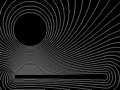
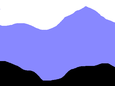
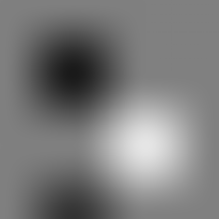
Another example using fanBW.bat:
|
Prepare an image with black, white and other colour(s): %IMG7%magick ^ -size 400x300 xc:#88f ^ -fill White -draw "circle 100,100,50,100" ^ -fill Black -draw "rectangle 50,250,350,260" ^ gr_shapeBW2b.png |

|
|
Use fanBW: call %PICTBAT%fanBW ^ gr_shapeBW2b.png ^ gr_shapeBW2b_out.png |

|
|
Show contours of the previous result: set FREQm1=29
%IMG7%magick ^
gr_shapeBW2b_out.png ^
( -size 1x500 gradient: -rotate 90 ^
-duplicate %FREQm1% +append +repage ) ^
-clut ^
-morphology edgein diamond:1 ^
-threshold 40%% ^
gr_shapeBW2b_cont.png
|
|
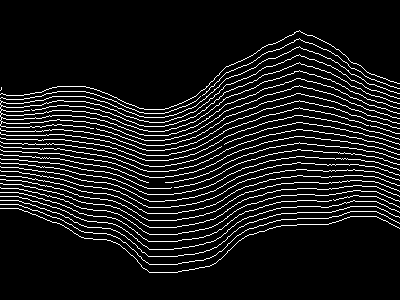
The contours look good. However, there is a weakness that is shown by shading the result:
%IMG7%magick ^ gr_shapeBW2b_out.png ^ -shade 135,45 ^ -auto-level ^ gr_shapeBW2b_shad.png |

|
The morphology distance from the circle is not smooth. When the light is nearly parallel to the surface tangent, we see the problem clearly. (The effect is similar to light glancing a brick wall or human face; we see the crevices clearly.)
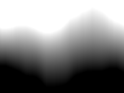
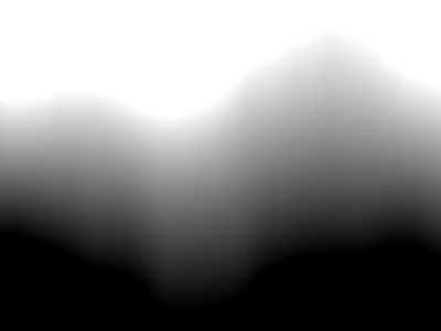
The script bwSegs.bat takes an input image that is in three segments: white pixels at the top, black at the bottom, and some other colours in the middle. The script will replace the other colours with a gradient between white and black.
It works by creating a a white to black gradient between the image top and the upper boundary of the black segment, then a white to black gradient from the lower boundary of the white segment to the image bottom, then doing a fan composition of the two generated gradients.
ASIDE: Part of this process is to create a gradient in the white pixels of each column of height H, where the top h pixels are white. So pixels from y=0 (the top) to y=h-1 (0 <= h <= H) are white, and any other pixels are black. For that image, the mean of the column on a scale of [0,1] would be (h/H). However, we crop off the top row which will be white (assuming any pixels in the column are white), so the mean of the column will be [(h-1)/(H-1)].
The script then makes a gradient from black at y=0 (the top) and white at y=H-1 (the bottom). At y, the value of this gradient is y/(H-1), for all columns.
The script divides the gradient in each column by the mean of the column, so the value at y is y/(H-1)/[(h-1)/(H-1)] = y/(h-1).
At y=0, the result is zero. At y=h-1, the result is (h-1)/(h-1) = 1.0 (white). At larger values of y, the result is larger than 1.0.For example we use Gimp to make segsForGrad.png with vertical segments of black, white and other colour(s):
|
segsForGrad.png |
|
|
Use bwSegs: call %PICTBAT%bwSegs ^ segsForGrad.png ^ gr_segsForGrad_out.png |
|
|
Show contours of the previous result: set FREQm1=29
%IMG7%magick ^
gr_segsForGrad_out.png ^
( -size 1x500 gradient: -rotate 90 ^
-duplicate %FREQm1% +append +repage ) ^
-clut ^
-morphology edgein diamond:1 ^
-threshold 40%% ^
gr_segsForGrad_cont.png
|
|
|
Shade the result: %IMG7%magick ^ gr_segsForGrad_out.png ^ -shade 135,45 ^ -auto-level ^ gr_segsForGrad_out_shad.png |

Yuck. |
|
Use bwSegs with blurs: set bwsProcBW=-blur 0x3 call %PICTBAT%bwSegs ^ segsForGrad.png ^ gr_segsForGrad_out2.png set bwsProcBW= |
|
|
Shade the result: %IMG7%magick ^ gr_segsForGrad_out2.png ^ -shade 135,45 ^ -auto-level ^ gr_segsForGrad_out2_shad.png The result is more pleasing. |

|
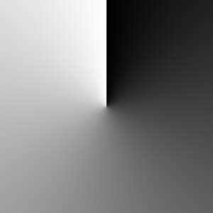
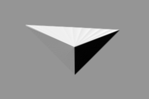
When we have a white shape on black background, and we want to create a gradient in the white area, an alternative method is:
This method works only if the shape's boundary is entirely visible from its centre. We implement this in the script shp2grad.bat.
The script first finds the "centre" of the shape, by default the pixel that is furthest from its edges, and uses that for the roll and unroll operations. Outside the shape, it creates values that are either less than zero or greater than 100%. These will be clamped to zero or 100% when we save to an integer format such as PNG, but will not be clamped when we save to a floating-point format such as MIFF or TIFF.
|
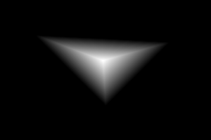
Make an example input: %IMG7%magick ^ -size 300x200 ^ xc:Black ^ -fill White ^ -draw "polygon 50,50 240,60 150,150" ^ gr_rgu.png |

|
|
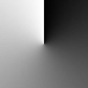
Make the gradient: call %PICTBAT%shp2grad ^ gr_rgu.png ^ gr_rgu_out.png ^ . -negate |

|
|
Shade the result: %IMG7%magick ^ gr_rgu_out.png ^ -shade 135,45 ^ -auto-level ^ gr_rgu_out_shad.png |
|
The script has alternative methods to calculate the centre:
|
Centroid: call %PICTBAT%shp2grad ^ gr_rgu.png ^ gr_rgu_centr.png ^ centroid -negate |
|
|
Centre of the bounding box: call %PICTBAT%shp2grad ^ gr_rgu.png ^ gr_rgu_bb.png ^ boundingbox -negate |

|
|
Centre at (200,70): call %PICTBAT%shp2grad ^ gr_rgu.png ^ gr_rgu_200x70.png ^ 200x70 -negate |

|
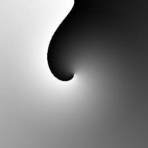
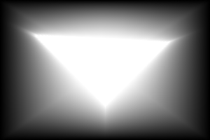
The script shp2gradOuter.bat creates the gradient from white at the shape to black at the image edges. It turns black into gray(50%) and unrolls with black virtual pixels, so we get white-gray-black segments. It makes a gradient from the image top to the lower boundary of the gray area, then another gradient from the upper boundary of the gray area to the bottom of the image, then fan-composites the two gradients, and finally unrolls.
call %PICTBAT%shp2gradOuter ^ gr_rgu.png ^ gr_rguout_out.png |
|
|
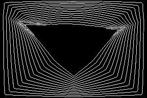
Show contours of the result: set FREQm1=14
%IMG7%magick ^
gr_rguout_out.png ^
( -size 1x500 gradient: -rotate 90 ^
-duplicate %FREQm1% +append +repage ) ^
-clut ^
-morphology edgein diamond:1 ^
-threshold 40%% ^
gr_rguout_cont.png
|
|
|
Shade the result: %IMG7%magick ^ gr_rguout_out.png ^ -shade 135,45 ^ -auto-level ^ gr_rguout_out_shad.png |

|
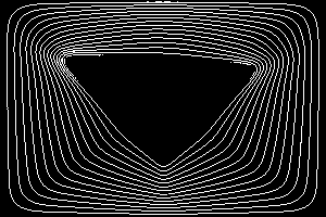
As usual, introducing a blur gives a cleaner and more pleasing result:
set shp2goProcBW=-blur 0x3 -auto-level call %PICTBAT%shp2gradOuter ^ gr_rgu.png ^ gr_rguoutbl_out.png set shp2goProcBW= |

|
|
Show contours of the result: set FREQm1=14
%IMG7%magick ^
gr_rguoutbl_out.png ^
( -size 1x500 gradient: -rotate 90 ^
-duplicate %FREQm1% +append +repage ) ^
-clut ^
-morphology edgein diamond:1 ^
-threshold 40%% ^
gr_rguoutbl_cont.png
|
|
|
Shade the result: %IMG7%magick ^ gr_rguoutbl_out.png ^ -shade 135,45 ^ -auto-level ^ gr_rguoutbl_out_shad.png |

|
Gradient from a specified centre to image edges:
set CX=100
set CY=150

%IMG7%magick ^
  -size 300x200 xc:White ^
  -virtual-pixel Black ^
  -distort DePolar -1,0,%CX%,%CY% ^
  -set option:MYSIZE %%wx%%h ^
  ( -size %%[MYSIZE] ^
    gradient:Black-White ^
  ) ^
  ( -clone 0 ^
    -crop 0x+0+1 +repage ^
    -scale "x1^!" ^
    -scale "%%[MYSIZE]^!" ^
  ) ^
  -delete 0 ^
  -compose DivideSrc -composite ^
  -clamp ^
  -virtual-pixel Edge ^
  -distort Polar -1,0,%CX%,%CY% ^
  -negate ^
  gr_cxcy.png
|

|
|
Shade the result: %IMG7%magick ^ gr_cxcy.png ^ -shade 135,45 ^ -auto-level ^ gr_cxcy_shad.png |

|
A clut ("Colour Look-Up Table") is an image of a one-dimensional array of colours, often representing a gradient. See the Clut Cookbook.
We can transform a clut into a two-dimensional gradient.
Method 1: Make a 1D clut then scale in the other dimension to 2D.
%IMG7%magick ^ xc: -bordercolor Black -border 2x0 ^ -filter gaussian ^ -resize "%WIDTH%x1^!" ^ -scale "%WIDTH%x%HEIGHT%^!" ^ gr_filtgauss.png |

|
Method 2: For a symmetrical clut we might want a rotation of half the clut. Make a 1D clut, crop the left half, rotate anti-clockwise, scale it in the other dimension, turn in a polar distortion. The output is square. Suppose we want the output radius to be OUT_RAD, so the output width and height will be 2*OUT_RAD+1.
set OUT_RAD=150
set /A outH=2*%OUT_RAD%
set /A outW=3*%OUT_RAD%
We write gr_filtgauss2.png only for illustration. This isn't normally needed. %IMG7%magick ^ xc: -bordercolor Black -border 2x0 ^ -filter gaussian ^ -resize "%outH%x1^!" ^ -crop %OUT_RAD%x1+0+0 +repage ^ -rotate -90 ^ -scale "%outW%x%OUT_RAD%^!" ^ -write gr_filtgauss2.png ^ +distort Polar ^"%OUT_RAD%,0 0.5,0.5^" ^ +repage ^ gr_filtgauss3.png |

|
The pixel colours from the circle (in this case, black) are spread to the corners. "-background Khaki -virtual-pixel HorizontalTile" might seem useful but we get a background colour at the centre pixel. If desired, we can isolate the circle:
%IMG7%magick ^
  gr_filtgauss3.png ^
  ( +clone ^
    -fill Black -colorize 100 ^
    -fill White -draw "circle %OUT_RAD%,%OUT_RAD% %OUT_RAD%,0" ^
  ) ^
  -alpha off ^
  -compose CopyOpacity -composite ^
  gr_filtgauss3c.png
|
|
Method 3: When we want a rotation of the entire clut, rotated around x=0. As method 2, but we don't crop, and the resize is different.
set OUT_RAD=150 set /A outH=%OUT_RAD% set /A outW=3*%OUT_RAD% %IMG7%magick ^ xc: -bordercolor Black -border 2x0 ^ -filter gaussian ^ -resize "%outH%x1^!" ^ -rotate -90 ^ -scale "%outW%x%OUT_RAD%^!" ^ +distort Polar ^"%OUT_RAD%,0 0.5,0.5^" ^ +repage ^ gr_filtgauss4.png |

|
Method 4: use two cluts, one for width the other for height, scale them up to the required size and combine them. When combining, we generally want at least the following conditions:
For example, using cluts that start and end at zero:
set WW=400
set HH=500
set PKx=150
set PKy=100

set P1h=%PKx%/%WW%
set S1h=%WW%/%PKx%
set S2h=%WW%/(%PKx%-%WW%)

set P1v=%PKy%/%HH%
set S1v=%HH%/%PKy%
set S2v=%HH%/(%PKy%-%HH%)

%IMG7%magick ^
  ( -size 1x%WW% gradient: -rotate 90 ^
    -fx "u<%P1h%?u*%S1h%:1+(u-%P1h%)*%S2h%" ^
    -function sinusoid 0.5,-90,0.5,0.5 ^
    -scale "%WW%x%HH%^!" ^
  ) ^
  ( -size 1x%HH% gradient: -flip ^
    -fx "u<%P1v%?u*%S1v%:1+(u-%P1v%)*%S2v%" ^
    -function sinusoid 0.5,-90,0.5,0.5 ^
    -scale "%WW%x%HH%^!" ^
  ) ^
  -compose Darken -composite ^
  gr_peak.png
|

|
|
As previous, but Multiply. %IMG7%magick ^
( -size 1x%WW% gradient: -rotate 90 ^
-fx "u<%P1h%?u*%S1h%:1+(u-%P1h%)*%S2h%" ^
-function sinusoid 0.5,-90,0.5,0.5 ^
-scale "%WW%x%HH%^!" ^
) ^
( -size 1x%HH% gradient: -flip ^
-fx "u<%P1v%?u*%S1v%:1+(u-%P1v%)*%S2v%" ^
-function sinusoid 0.5,-90,0.5,0.5 ^
-scale "%WW%x%HH%^!" ^
) ^
-compose Multiply -composite ^
gr_peak2.png
|

|
|
As previous, but geometric mean. %IMG7%magick ^
( -size 1x%WW% gradient: -rotate 90 ^
-fx "u<%P1h%?u*%S1h%:1+(u-%P1h%)*%S2h%" ^
-function sinusoid 0.5,-90,0.5,0.5 ^
-scale "%WW%x%HH%^!" ^
) ^
( -size 1x%HH% gradient: -flip ^
-fx "u<%P1v%?u*%S1v%:1+(u-%P1v%)*%S2v%" ^
-function sinusoid 0.5,-90,0.5,0.5 ^
-scale "%WW%x%HH%^!" ^
) ^
-compose Multiply -composite ^
-evaluate Pow 0.5 ^
gr_peak2a.png
|

|
|
As previous, but arithmetic mean. %IMG7%magick ^
( -size 1x%WW% gradient: -rotate 90 ^
-fx "u<%P1h%?u*%S1h%:1+(u-%P1h%)*%S2h%" ^
-function sinusoid 0.5,-90,0.5,0.5 ^
-scale "%WW%x%HH%^!" ^
) ^
( -size 1x%HH% gradient: -flip ^
-fx "u<%P1v%?u*%S1v%:1+(u-%P1v%)*%S2v%" ^
-function sinusoid 0.5,-90,0.5,0.5 ^
-scale "%WW%x%HH%^!" ^
) ^
-evaluate-sequence Mean ^
gr_peak3.png
|

|
This is useful, so we make a general-purpose script: mPntEdgeMsk.bat. This also has a parameter that can smooth the start or end of the transition, or both.
|
"+level-colors" for a simple gradient. %IMG7%magick ^ gr_clock4s.png ^ +level-colors red,lime ^ gr_col1.png |
|
|
"-clut" for more complexity. %IMG7%magick ^
gr_clock4s.png ^
( -size 1x1 ^
xc:#004 xc:#404 xc:#800 xc:#f00 xc:#f80 xc:#ff0 xc:#ffa ^
+append +repage ^
) ^
-clut ^
gr_col2.png
As the input is greyscale, "-hald-clut" would be of no extra benefit. |
|
|
Greyscale gradients can be combined into channels. %IMG7%magick ^ -size %WIDTH%x%HEIGHT% ^ gradient: ^ radial-gradient: ^ -size %HEIGHT%x%WIDTH% ^ ( gradient: -rotate 90 ) ^ -combine ^ gr_col3.png |
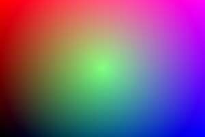
|
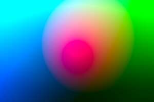
|
The same, but combining in a different colorspace. %IMG7%magick ^ -size %WIDTH%x%HEIGHT% ^ gradient: ^ radial-gradient: ^ -size %HEIGHT%x%WIDTH% ^ ( gradient: -rotate 90 ) ^ -set colorspace Lab -combine -colorspace sRGB ^ gr_col4.png |
|
We can easily construct a gradient between two colours, as a straight line between the colours in the sRGB colorspace cube:
%IMG7%magick ^ -size 11x1 ^ gradient:rgb(100%%,0,0)-rgb(0,100%%,0) ^ -scale 5000%% ^ gr_g2c_1.png |

|
The intermediate values are linear interpolations between the end-points, so the central colour is (50%,50%,0). That tuple in the sRGB colorspace is darker than either of the endpoints.
The end-points we have chosen (red and green) are fully saturated, so they have the same values in linear RGB and non-linear sRGB. Hence, we can push the output through an RGB->sRGB transformation, so the gradient operates in RGB space:
%IMG7%magick ^ -size 11x1 ^ gradient:rgb(100%%,0,0)-rgb(0,100%%,0) ^ -set colorspace RGB ^ -colorspace sRGB ^ -scale 5000%% ^ gr_g2c_2.png |

|
The central colour is again (50%,50%,0), but that tuple in linear RGB space is closer to the average lightness of the endpoints.
More generally, we can use any pair of colours in any colorspace. We specify the colours with two tuples or named colours in that colorspace, create the gradient, set the image to the colorspace, and convert to sRGB or whatever we want.
If we don't know the tuple values of our desired colour in the required colorspace, we can use IM to do the conversion. IM doesn't contain facilities to do this directly, so we go via a script, twoColVals.bat, that creates an image with those colours, converts it to the colorspace, and captures the values so we can use those in the "gradient:". With Lab values, IM is inconsistent: sometimes it writes and expects a range of 0 to 100%, sometimes -50% to +50%. To avoid that problem, the script uses "-set colorspace sRGB" to pretend the result is sRGB.
call %PICTBAT%twoColVals sRGB #f00 #0f0 Lab mylab

set mylab
mylab[0]=srgb(53.24079571030747%,81.40880707827878%,76.35419646944381%)
mylab[1]=srgb(87.73472071221485%,16.20285647697795%,82.61934224078736%)
These are really Lab values, not sRGB values.
Now we can create a gradient between those colours in Lab colorspace:
%IMG7%magick ^ -size 11x1 ^ gradient:%mylab[0]%-%mylab[1]% ^ -set colorspace Lab ^ -colorspace sRGB ^ -scale 5000%% ^ gr_g2c_3.png |

|
The result is more perceptually uniform than the sRGB or RGB gradients. The central colour has exactly the average lightness (in Lab terms) of the endpoints.
Another useful result is in xyY colorspace:
call %PICTBAT%twoColVals ^ sRGB #f00 #0f0 xyY myxyy %IMG7%magick ^ -size 11x1 ^ gradient:%myxyy[0]%-%myxyy[1]% ^ -set colorspace xyY ^ -colorspace sRGB ^ -scale 5000%% ^ gr_g2c_4.png |

|
We can define a small NxM image, and enlarge it with "-filter Hermite" retaining the aspect ratio. The result will have the original values in a grid, with interpolated values between them.
This is an extension of Clut cookbook: cluts from resize, but with a different filter.
We also crop the image.
set N=4 set M=4 %IMG7%magick ^ -size 4x4 xc:gray(50%%) ^ -fill gray(10%%) -draw "point 1,1" ^ -fill gray(90%%) -draw "point 2,2" ^ -fill gray(20%%) -draw "point 1,3" ^ -filter Hermite ^ -resize "600x600^!" ^ -crop "%%[fx:w*(%N%-1)/%N%+2]x%%[fx:h*(%M%-1)/%M%+2]+%%[fx:w/%N%/2-1]+%%[fx:h/%M%/2-1]" ^ +repage ^ gr_grgrd.png |
|
Masks can be combined:
%IMG7%magick ^ gr_baseGrad.png ^ gr_blobMask2.png ^ -compose Overlay -composite ^ gr_combMask.png |

|
A mask may be clutted to transform black-white into a number of ramps; in this case 4. "-interpolate nearest-neighbor" ensures we don't get grey anti-aliasing at the black/white boundaries.
%IMG7%magick -size 1x1000 gradient: ^ -rotate 90 ^ -duplicate 3 ^ +append +repage ^ gr_ramp_clut.png %IMG7%magick -size %WIDTH%x%HEIGHT% radial-gradient: ^ -interpolate nearest-neighbor ^ gr_ramp_clut.png -clut ^ gr_ramp.png |

|
The previous result can give us the three contours at 25% intervals:
%IMG7%magick ^ gr_ramp.png ^ -morphology edgein diamond:1 ^ gr_rampCont.png |

|
We might want fill a rectangle with a gradient, with black at top-left and white bottom-right, increasing lightness across then down:
set WW=300 set HH=200 set /A WH=%WW%*%HH% %IMG7%magick ^ -size %WH%x1 ^ gradient:Black-White ^ -crop %WW%x ^ -append +repage ^ gr_reading.png |

|
If we have a white shape on black background, we can make each line of the shape a gradient with black at the left and white at the right. Annoyingly, "-auto-level" doesn't ignore transparent pixels; it merely ignores the alpha channel. So we fill in transparent pixels with the average of each row.
|
shapeB.png: |
|
for /F "usebackq" %%L in (`%IMG7%magick identify ^
  -format "WW=%%w\nHH=%%h\nWm1=%%[fx:w-1]\nHm1=%%[fx:h-1]" ^
  shapeB.png`) do set %%L

%IMG7%magick ^
  shapeB.png ^
  ( +clone ^
    -sparse-color Bilinear ^
      "0,0,Black %%[fx:w-1],0,White" ^
  ) ^
  +swap ^
  -alpha off ^
  -compose CopyOpacity -composite ^
  ( +clone ^
    -scale "1x%HH%^!" ^
    -scale "%WW%x%HH%^!" ^
  ) ^
  -compose DstOver -composite ^
  -crop x1 ^
  -auto-level ^
  -append +repage ^
  +repage ^
  gr_sh_grad.png
|
|
We put this in a script, sh2grad.bat. The script can also rotate the input before processing, and de-rotate afterwards.
The script sh2gradCol.bat calls sh2grad.bat for the red and green channels, setting blue to 50%, and marks pixels outside the shape with black. The result is an absolute displacement map from the rectangle to the shape.
call %PICTBAT%sh2gradCol ^ shapeB.png gr_sh_grad2.png |

|
The result has many pixels with red==0 and green==0, so these will all be displaced from the top-left corner of the rectangle. Similarly for the other corners.
For convenience, .bat scripts are also available in a single zip file. See Zipped BAT files.
rem Generates a mask width %1 height %2, corners coloured with percentages of grey:
rem   %3 top-left
rem   %4 top-right
rem   %5 bottom-left
rem   %6 bottom-right
rem Width and height must be at least 2.
rem Useful percentages: 0=black, 100=white
@rem
@rem Updated:
@rem   5-August-2022 for IM v7.
@rem

"%IMG7%magick" -size %1x%2 xc: ^
  -sparse-color Bilinear "0,0 rgb(%3%%,%3%%,%3%%) %%[fx:w-1],0 rgb(%4%%,%4%%,%4%%) 0,%%[fx:h-1] rgb(%5%%,%5%%,%5%%) %%[fx:w-1],%%[fx:h-1] rgb(%6%%,%6%%,%6%%)" ^
  greyRectMask.png
@%PICTBAT%ellipMaskCornColbat,h
rem Generates a grayscale elliptical mask,
rem   width %1 height %2,
rem   centre %3 [default white] fading to %4 [black] at corners.
rem Colours are percentages gray, eg 0=white, 50=mid gray, 100=white
rem The image is contained within the ellipse, so only the corners are the background grey.
@rem
@rem Updated:
@rem   5-August-2022 for IM v7.
@rem

set WI=%1

set HT=%2
if "%HT%"=="" set HT=%1

set SIZ=%WI%
if %SIZ% LSS %HT% set SIZ=%HT%

set INCOL=%3
if "%INCOL%"=="" set INCOL=100

set OUTCOL=%4
if "%OUTCOL%"=="" set OUTCOL=0

for /F %%i in ('%IMG7%magick ^
  xc: ^
  -format "%%[fx:int(%SIZ%*sqrt(2)+0.5)]" ^
  info:') do set SQ_DIM=%%i

%IMG7%magick -size %SQ_DIM%x%SQ_DIM% ^
  radial-gradient:rgb(%INCOL%%%,%INCOL%%%,%INCOL%%%)-rgb(%OUTCOL%%%,%OUTCOL%%%,%OUTCOL%%%) ^
  -gravity Center ^
  -crop %SIZ%x%SIZ%+0+0 +repage ^
  -resize "%WI%x%HT%^!" ^
  ellipMaskCorn.png

%IMG7%magick identify ellipMaskCorn.png
rem Generates a mask darker at the bottom, especially the corners,
rem   width %1 height %2,
rem   only dark at bottom %3 percent of image.
@rem
@rem Updated:
@rem   5-August-2022 for IM v7.
@rem

call %PICTBAT%ellipMaskCorn %1 %2

"%IMG7%magick" ^
  -size %1x%2 gradient: -level 0x%3%% ^
  ellipMaskCorn.png ^
  -compose Screen -composite ^
  baseMask.png
rem Given image %1 and percentage offset (%2,%3),
rem intended range (-50,-50) to (50,50),
rem creates image %4
rem with centre shifted by the offset.
rem Optional %5 %6 %7 %8 %9: extra parameters for magick.
@rem
@rem Updated:
@rem   5-August-2022 for IM v7.
@rem

rem SETLOCAL

FOR /F "tokens=1,2" %%i IN ('%IMG7%magick identify -ping -format "%%w %%h" %1') DO (
  set wi=%%i
  set ht=%%j
)

set opts=%5 %6 %7 %8 %9
rem eg rem -filter Point -interpolate Integer

set /A offX=%2
set /A offY=%3

set /A wim1=%wi%-1
set /A htm1=%ht%-1

set /A cx=%wi%/2
set /A cy=%ht%/2

set /A cxpo=%wi%/2+offX*%wi%/100
set /A cypo=%ht%/2+offY*%ht%/100

echo %cxpo%
echo %cypo%

set pinL=0
set pinT=0
set pinR=0
set pinB=0

if %offX% geq 0 set pinL=1
if %offY% geq 0 set pinT=1
if %offX% leq 0 set pinR=1
if %offY% leq 0 set pinB=1

set /A pinTL=%pinT%+%pinL%
set /A pinTR=%pinT%+%pinR%
set /A pinBL=%pinB%+%pinL%
set /A pinBR=%pinB%+%pinR%

echo %pinTL% %pinTR% %pinBL% %pinBR%

rem We pin the 4 corners, the centre-edges, and the edges at cxpo and cypo.

set pin=%cx%,%cy%,%cxpo%,%cypo%

rem Do corners
if %pinTL% gtr 0 set pin=%pin% 0,0,0,0
if %pinTR% gtr 0 set pin=%pin% %wim1%,0,%wim1%,0
if %pinBL% gtr 0 set pin=%pin% 0,%htm1%,0,%htm1%
if %pinBR% gtr 0 set pin=%pin% %wim1%,%htm1%,%wim1%,%htm1%

rem Do edges
if %pinL% gtr 0 set pin=%pin% 0,%cypo%,0,%cypo% 0,%cy%,0,%cy%
if %pinT% gtr 0 set pin=%pin% %cxpo%,0,%cxpo%,0 %cx%,0,%cx%,0
if %pinR% gtr 0 set pin=%pin% %wim1%,%cypo%,%wim1%,%cypo% %wim1%,%cy%,%wim1%,%cy%
if %pinB% gtr 0 set pin=%pin% %cxpo%,%htm1%,%cxpo%,%htm1% %cx%,%htm1%,%cx%,%htm1%

echo %pin%

%IMG7%magick ^
  %1 ^
  %opts% ^
  -distort Shepards ^"%pin%^" ^
  %4

rem ENDLOCAL
rem Makes a tiled diamond gradient mask.
rem %1 is output filename.
rem %2 and %3 are overall width and height.
rem %4 and %5 are repetitions horizontally and vertically (default 1).
@rem
@rem Updated:
@rem   5-August-2022 for IM v7.
@rem

set outName=%1
if "%outName%"=="" set outName=diamondMask.png

set numWi=%4
if "%numWi%"=="" set numWi=1

set numHt=%5
if "%numHt%"=="" set numHt=1

set /A oneWi=%2/%numWi%
set /A oneHt=%3/%numHt%

echo %oneWi% %oneHt%

set /A outWi=%numWi%*%oneWi%
set /A outHt=%numHt%*%oneHt%

echo %outWi% %outHt%

set /A semiHt=%oneHt%/2
set /A oneHt=%semiHt%*2
set /A semiWi=%oneWi%/2
set /A outHt=%numHt%*%oneHt%

echo %outWi% %outHt%

set /A oneWim1=%oneWi%-1
set /A oneHtm1=%oneHt%-1

%IMG7%magick ^
  -size %oneWi%x%oneHt% ^
  xc:White ^
  -fill Black ^
  -draw ^"polygon %semiWi%,0 %oneWim1%,%semiHt% %semiWi%,%oneHtm1% 0,%semiHt%^" ^
  +repage ^
  %TEMP%\dmMask.png


rem We could use -crop 1x2@ instead of two clones and crops, but we want exact control of the size.

%IMG7%magick ^
  -size %oneWi%x%oneHt% ^
  gradient: ^
  -write %TEMP%\dm0.png ^
  ( -clone 0 -crop %oneWi%x%semiHt%+0+%semiHt% ) ^
  ( -clone 0 -crop %oneWi%x%semiHt%+0+0 ) ^
  -delete 0 ^
  -append ^
  +repage ^
  %TEMP%\dm1.png

%IMG7%magick ^
  %TEMP%\dm0.png ^
  ( %TEMP%\dm1.png -alpha set %TEMP%\dmMask.png -alpha off -compose Copy-Opacity -composite ) ^
  -compose Over -composite ^
  %TEMP%\dmOne.png

rem This starts tiling top-left, so any partial tiles will be at right and bottom.
rem We could use -tile-offset, or generate over-size then trim.

%IMG7%magick ^
  -size %2x%3 ^
  tile:%TEMP%\dmOne.png ^
  %outName%
rem Makes a tiled blob gradient mask.
rem %1 is output filename.
rem %2 and %3 are overall width and height.
rem %4 and %5 are repetitions horizontally and vertically (default 1).
rem %6 is blur sigma (default 10).
rem %7 0 for greyscale, 1 for colour
@rem
@rem Also uses:
@rem   mbmSEED if given, use this as seed.
@rem
@rem Updated:
@rem   25-May-2016 added mbmSEED feature.
@rem   5-August-2022 for IM v7.
@rem


@if "%3"=="" findstr /B "rem @rem" %~f0 & exit /B 1

@setlocal enabledelayedexpansion

@call echoOffSave

call %PICTBAT%setInOut %1 mbm


set OUTFILE=%1
if "%OUTFILE%"=="" set OUTFILE=blobMask.png

set numWi=%4
if "%numWi%"=="." set numWi=
if "%numWi%"=="" set numWi=1

set numHt=%5
if "%numHt%"=="." set numHt=
if "%numHt%"=="" set numHt=1

set blurSig=%6
if "%blurSig%"=="." set blurSig=
if "%blurSig%"=="" set blurSig=10

set IsCol=%7
if "%IsCol%"=="." set IsCol=
if "%IsCol%"=="" set IsCol=0

set sSEED=
if not "%mbmSEED%"=="" set sSEED=-seed %mbmSEED%

set TEMP_FILE=%TEMP%\bmOne.miff

set /A oneWi=%2/%numWi%
set /A oneHt=%3/%numHt%

echo %oneWi% %oneHt%

set /A semiHt=%oneHt%/2
set /A oneHt=%semiHt%*2
set /A semiWi=%oneWi%/2

set /A oneWim1=%oneWi%-1
set /A oneHtm1=%oneHt%-1

if %IsCol%==0 (
  set sCOL=-modulate 100,0,100
) else (
  set sCOL=-channel RGB
)

rem This starts tiling top-left, so any partial tiles will be at right and bottom.
rem We could use -tile-offset, or generate over-size then trim.

goto skip

%IMG7%magick ^
  -size %oneWi%x%oneHt% ^
  xc: ^
  %sSEED% +noise Random ^
  -virtual-pixel Tile ^
  -blur 0,%blurSig% ^
  -modulate 100,0,100 ^
  -auto-level ^
  -auto-gamma ^
  %TEMP_FILE%

%IMG7%magick ^
  -size %2x%3 ^
  tile:%TEMP_FILE% ^
  %OUTFILE%
:skip

%IMG7%magick ^
  -size %oneWi%x%oneHt% ^
  xc: ^
  %sSEED% +noise Random ^
  -virtual-pixel Tile ^
  -blur 0,%blurSig% ^
  %sCOL% ^
  -auto-level ^
  -auto-gamma ^
  +channel ^
  +write mpr:NSE +delete ^
  -size %2x%3 ^
  tile:mpr:NSE ^
  %OUTFILE%

call echoRestore

@endlocal & set mbmOUTFILE=%OUTFILE%
rem %1 is input image file
rem %2 is output image file
rem %3 is number of iterations
@rem
@rem Updated:
@rem   5-August-2022 for IM v7.
@rem

setlocal ENABLEDELAYEDEXPANSION

set INFILE=%1

set OUTFILE=%2

set NITER=%3
if "%NITER%"=="" set NITER=2

if /I %NITER% LSS 1 goto bad

set /A nClone=0
set /A nBlur=1

set strDB=

for /L %%i in (1,1,%NITER%) do (
  set strDB=!strDB! ^( -clone !nClone! -gaussian-blur x!nBlur! -auto-level ^)
  set /A nClone+=1
  set /A nBlur*=2
)

echo %strDB%

%IMG7%magick ^
  %1^
  %strDB% ^
  -evaluate-sequence Mean ^
  +depth ^
  %2

goto :eof

:bad
echo Call with: infile outfile niter
rem Given %1 is white shape on black background,
rem replaces shape with each line gradient
rem with black at left of shape, white at right of shape.
rem %2 output.
rem %3 rotate degrees clockwise before processing (and de-rotate after).
@rem
@rem Updated:
@rem   5-August-2022 for IM v7.
@rem


@if "%1"=="" findstr /B "rem @rem" %~f0 & exit /B 1

@setlocal enabledelayedexpansion

@call echoOffSave

call %PICTBAT%setInOut %1 s2g

if not "%2"=="" set OUTFILE=%2

set nROT=%3
if "%nROT%"=="." set nROT=
if "%nROT%"=="" set nROT=0

if %nROT%==0 (
  set IN_ROT=
  set OUT_ROT=
) else (
  set IN_ROT=-rotate %nROT% +repage
  set OUT_ROT=-rotate -%nROT% +repage
  set OUT_ROT=!OUT_ROT:--=!
)

set TMP_IMG=s2g_tmp.miff

%IMG7%magick ^
  %INFILE% ^
  -background Black ^
  %IN_ROT% ^
  +depth ^
  %TMP_IMG%

for /F "usebackq" %%L in (`%IMG7%magick identify ^
  -format "WW=%%w\nHH=%%h" ^
  %TMP_IMG%`) do set %%L

%IMG7%magick ^
  %TMP_IMG%^
  ( +clone ^
    -sparse-color Bilinear ^
      "0,0,Black %%[fx:w-1],0,White" ^
  ) ^
  +swap ^
  -alpha off ^
  -compose CopyOpacity -composite ^
  ( +clone ^
    -scale "1x%HH%^!" ^
    -scale "%WW%x%HH%^!" ^
    -alpha Opaque ^
  ) ^
  -compose DstOver -composite ^
  -crop x1 ^
  -auto-level ^
  -append ^
  +repage ^
  -background Black ^
  %OUT_ROT% ^
  %OUTFILE%

call echoRestore

@endlocal & set s2gOUTFILE=%OUTFILE%
rem Given %1 is white shape on black background,
rem replaces shape with each absolute displacement map
rem from rectangle to shape.
rem %2 output.
@rem
@rem Updated:
@rem   5-August-2022 for IM v7.
@rem

@if "%1"=="" findstr /B "rem @rem" %~f0 & exit /B 1

@setlocal enabledelayedexpansion

@call echoOffSave

call %PICTBAT%setInOut %1 s2gc

if not "%2"=="" set OUTFILE=%2

call %PICTBAT%sh2grad %INFILE% s2gc_red.miff
if ERRORLEVEL 1 exit /B 1

call %PICTBAT%sh2grad %INFILE% s2gc_grn.miff -90
if ERRORLEVEL 1 exit /B 1

%IMG7%magick ^
  s2gc_red.miff ^
  s2gc_grn.miff ^
  ( +clone -fill gray(50%%) -colorize 100 ) ^
  -combine ^
  %INFILE% ^
  -alpha off ^
  -compose CopyOpacity -composite ^
  -background Black -compose Over -layers Flatten ^
  %OUTFILE%
if ERRORLEVEL 1 exit /B 1

call echoRestore

@endlocal & set s2gcOUTFILE=%OUTFILE%
rem Given %1 is slopeXY structure (thus contains 2 images),
rem returns %2 conventional RGB image
rem with each channel set to direction.
rem %3 if SWAP, swap the two inputs.
rem %4 if SUB, subtract 50% before taking the arctan.
rem %5 percentage for addmodulus.
@rem
@rem Updated:
@rem   5-August-2022 for IM v7.
@rem

@if "%2"=="" findstr /B "rem @rem" %~f0 & exit /B 1

@setlocal

@call echoOffSave

call %PICTBAT%setInOut %1 sxyd

if not "%2"=="" set OUTFILE=%2

set SWAP=%3
if "%SWAP%"=="." set SWAP=
if "%SWAP%"=="" set SWAP=0

set SUBHALF=%4
if "%SUBHALF%"=="." set SUBHALF=
if "%SUBHALF%"=="" set SUBHALF=0

set nADDMOD=%5
if "%nADDMOD%"=="." set nADDMOD=
if "%nADDMOD%"=="" set nADDMOD=0

if /I "%SWAP%"=="SWAP" (
  set sSWAP=+swap
) else (
  set sSWAP=
)

if /I "%SUBHALF%"=="SUB" (
  set sSUBHALF=-evaluate Subtract 50%%
) else (
  set sSUBHALF=
)

echo %0: sSWAP=%sSWAP% sSUBHALF=%sSUBHALF% nADDMOD=%nADDMOD%

%IM7DEV%magick ^
  %INFILE% ^
  %sSWAP% ^
  %sSUBHALF% ^
  -process 'arctan2 b 0' ^
  -evaluate AddModulus %nADDMOD%%% ^
  +depth ^
  -depth 32 ^
  -define quantum:format=floating-point ^
  %OUTFILE%

if ERRORLEVEL 1 exit /B 1

call echoRestore

endlocal & set sxydOUTFILE=%OUTFILE%
rem Make a mask white at point, black at edges.
rem %1 output file
rem %2 WWxHH image width and height, pixels, eg 1920x1080
rem %3 quoted CX,CY centre
rem %4 composite method [gm]
rem %5 smoothing: none, start, end, or both [none]
rem %6 L1, percentage start of gradation [0]
rem %7 L2, percentage start of gradation [100]

@if "%1"=="" findstr /B "rem @rem" %~f0 & exit /B 1

@setlocal

@call echoOffSave

call %PICTBAT%setInOut %1 pem

set OUTFILE=%1

set IMGSIZE=%2
if "%IMGSIZE%"=="." set IMGSIZE=
if "%IMGSIZE%"=="" set IMGSIZE=600x400
call parseXxY2 600 400 pem_ %IMGSIZE%

set CENT=%3
if [%CENT%]==[.] set CENT=
if [%CENT%]==[] (
  set CX=0.5
  set CY=0.5
  set CENT="!CX!,!CY!"
)
call parseCommaList %CENT% pem_argc pem_argv
if ERRORLEVEL 1 exit /B 1
call propOfProp %pem__X% %pem_argv[0]% pem_argv[0]
if ERRORLEVEL 1 exit /B 1
call propOfProp %pem__Y% %pem_argv[1]% pem_argv[1]
if ERRORLEVEL 1 exit /B 1

set WW=%pem__X%
set HH=%pem__Y%

set CX=%pem_argv[0]%
set CY=%pem_argv[1]%

set pem_

set P1h=%CX%
set S1h=1/%CX%
set S2h=1/(%CX%-1)

set P1v=%CY%
set S1v=1/%CY%
set S2v=1/(%CY%-1)

set MTHD=%4
if "%MTHD%"=="." set MTHD=
if "%MTHD%"=="" set MTHD=gm

set SMTH=%5
if "%SMTH%"=="." set SMTH=
if "%SMTH%"=="" set SMTH=none

set L1=%6
if "%L1%"=="." set L1=
if "%L1%"=="" set L1=0

set L2=%7
if "%L2%"=="." set L2=
if "%L2%"=="" set L2=100

set sLEV=
if %L1% NEQ 0 if %L2% NEQ 100 (
  set sLEV=-level %L1%%%,%L2%%%
)

if /I "%MTHD%"=="Darken" (
  set COMPOS=-compose Darken -composite
) else if /I "%MTHD%"=="Lighten" (
  set COMPOS=-compose Lighten -composite
) else if /I "%MTHD%"=="Mean" (
  set COMPOS=-evaluate-sequence Mean
) else if /I "%MTHD%"=="Multiply" (
  set COMPOS=-compose Multiply -composite
) else if /I "%MTHD%"=="gm" (
  set COMPOS=-compose Multiply -composite -evaluate Pow 0.5
) else (
  echo %0: Bad MTHD [%MTHD%]
  exit /B 1
)

if /I "%SMTH%"=="none" (
  set sSMTH=
) else if /I "%SMTH%"=="start" (
  set sSMTH=-function sinusoid 0.25,-90,1,1
) else if /I "%SMTH%"=="end" (
  set sSMTH=-function sinusoid 0.25,0,1,0
) else if /I "%SMTH%"=="both" (
  set sSMTH=-function sinusoid 0.5,-90,0.5,0.5
) else (
  echo %0: Bad SMTH [%SMTH%]
  exit /B 1
)

%IMG7%magick ^
  ( -size 1x%WW% gradient: -rotate 90 ^
    -fx "u<%P1h%?u*%S1h%:1+(u-%P1h%)*%S2h%" ^
    %sSMTH% ^
    -scale "%WW%x%HH%^!" ^
  ) ^
  ( -size 1x%HH% gradient: -flip ^
    -fx "u<%P1v%?u*%S1v%:1+(u-%P1v%)*%S2v%" ^
    %sSMTH% ^
    -scale "%WW%x%HH%^!" ^
  ) ^
  %COMPOS% ^
  %sLEV% ^
  %OUTFILE%

call echoRestore

@endlocal
rem %1 input with back, white and other.
rem %2 output, replacing "other" with graduated gray.
rem Method: morphology distance, then fan composition.
@rem
@rem Updated:
@rem   4-March-2023 changed Euclidean:4 to Euclidean:7

set INFILE=%1
set OUTFILE=%2

%IMG7%magick ^
  %INFILE% ^
  -alpha off ^
  ( -clone 0 ^
    -channel RGB -negate +channel ^
    -fill White +opaque Black ^
    -morphology Distance Euclidean:7 ^
    -channel RGB -negate +channel ^
    -auto-level ^
  ) ^
  ( -clone 0 ^
    -fill White +opaque Black ^
    -morphology Distance Euclidean:7 ^
    -auto-level ^
    -evaluate Divide 2 ^
  ) ^
  -delete 0 ^
  ( -clone 0-1 ^
    -compose Mathematics ^
      -define compose:args=0,1,-0.5,0.5 ^
      -composite ^
  ) ^
  -delete 0 ^
  -compose DivideSrc -composite ^
  %OUTFILE%
rem %1 is input image with horizontal areas white and black, with other colours in between,
rem %2 is output with other segment replaced by grayscale gradient.
@rem
@rem Also uses:
@rem   bwsProcBW processing for the black and white images, eg -blur 0x3

%IMG7%magick ^
  %1 ^
  -set option:MYSIZE %%wx%%h ^
  ( -clone 0 ^
    -fill White +opaque Black ^
    %bwsProcBW% ^
    ( -size %%[MYSIZE] ^
      gradient:Black-White ^
    ) ^
    ( -clone 0 ^
      -crop 0x+0+1 +repage ^
      -scale "x1^!" ^
      -scale "%%[MYSIZE]^!" ^
    ) ^
    -delete 0 ^
    -compose DivideSrc -composite ^
    -clamp ^
    -negate ^
  ) ^
  ( -clone 0 ^
    -flip -negate ^
    -fill White +opaque Black ^
    %bwsProcBW% ^
    ( -size %%[MYSIZE] ^
      gradient:Black-White ^
    ) ^
    ( -clone 0 ^
      -crop 0x+0+1 +repage ^
      -scale "x1^!" ^
      -scale "%%[MYSIZE]^!" ^
    ) ^
    -delete 0 ^
    -compose DivideSrc -composite ^
    -clamp ^
    -flip ^
  ) ^
  -delete 0 ^
  -fx "u/(u-v+1)" ^
  %2
rem %1 input image, white shape on black background.
rem %2 output, replacing white with gradient from black at the centre to white at edge of shape.
rem %3 centre: "furthest" or "centroid" or "boundingbox" or "XxY" where X and Y are numbers each possibly suffixed by %% or c or p.
rem      default is point at furthest distance from shape edge.
rem %4 post processing, eg "-negate".
@rem
@rem Also uses:
@rem   shp2gProcBW process for the unrolled black and white image, eg -blur 0x3 -auto-level
@rem
@rem Updated:
@rem   4-March-2023 changed Euclidean:4 to Euclidean:7
@rem   8-August-2023 added parameter %3
@rem   13-August-2023: removed "-clamp" before "-distort Polar"
@rem   18-August-2023: added %4.
@rem     Changed default from "white at the centre to black at edge of shape" to "black at the centre to white at edge of shape".
@rem     If old default is wanted, use "-negate" in %4
@rem

@if "%1"=="" findstr /B "rem @rem" %~f0 & exit /B 1

@setlocal enabledelayedexpansion

@call echoOffSave

call %PICTBAT%setInOut %1 shp2g

if not "%2"=="" set OUTFILE=%2

set sCent=%3
if "%sCent%"=="." set sCent=
if "%sCent%"=="" set sCent=furthest

set sPROC=%~4
if "%sPROC%"=="." set sPROC=

set CX=

call %PICTBAT%shpCent %INFILE% %sCent% s2g

goto skipCent

if /I "%sCent%"=="furthest" (

  for /F "usebackq tokens=1,4,5 delims=:, " %%A in (`%IMG7%magick ^
    %INFILE% ^
    -morphology Distance Euclidean:7 ^
    -alpha off -auto-level ^
    -define "identify:locate=maximum" ^
    -define "identify:limit=1" ^
    -identify ^
    NULL:`) do (
    if /I "%%A"=="Gray" (
      set CX=%%B
      set CY=%%C
    )
  )

) else if /I "%sCent%"=="centroid" (

  for /F "usebackq skip=1 tokens=3-6 delims=, " %%A in (`%IMG7%magick ^
    %INFILE% -alpha off -threshold 50% ^
    -define "connected-components:verbose=true" ^
    -connected-components 8 ^
    NULL:`) do (
    if "%%D"=="gray(255)" (
      set CX=%%A
      set CY=%%B
    )
  )

) else if /I "%sCent%"=="boundingbox" (

  for /F "usebackq" %%L in (`%IMG7%magick ^
    %INFILE% -alpha off -threshold 50% ^
    -trim ^
    -format "CX=%%[fx:(w-1)/2+page.x]\nCY=%%[fx:(h-1)/2+page.y]\n" ^
    info:`) do set %%L

) else (
  for /F "usebackq" %%A in (`%IMG7%magick ^
    %INFILE% -format "WW=%%w\nHH=%%h\n" ^
    info:`) do set %%A

  call parseXxY2 !WW! !HH! acw %sCent%

  set CX=!acw_X!
  set CY=!acw_Y!
)

echo %0: CX=%CX% CY=%CY%

if "!CX!"=="" (
  echo %0: sCent=%sCent%  no CX
  exit /B 1
)

:skipCent

@rem 13-August-2023: removed "-clamp" before "-distort Polar"
@rem 19-August-2023: This had "-crop 0x+0+1 +repage" after "-clone 0". That removed the top (white) row before scaling.
@rem   I forget why I did this. Remove it.

%IMG7%magick ^
  %INFILE% ^
  -define compose:clamp=off ^
  -distort DePolar -1,0,%s2g_CX%,%s2g_CY% ^
  -set option:MYSIZE %%wx%%h ^
  %shp2gProcBW% ^
  ( -size %%[MYSIZE] ^
    gradient:Black-White ^
  ) ^
  ( -clone 0 ^
    -scale "x1^!" ^
    -scale "%%[MYSIZE]^!" ^
  ) ^
  -delete 0 ^
  -compose DivideSrc -composite ^
  -distort Polar -1,0,%s2g_CX%,%s2g_CY% ^
  -define quantum:format=floating-point -depth 32 ^
  %sPROC% ^
  %OUTFILE%

if ERRORLEVEL 1 exit /B 1

call echoRestore

@endlocal & set shp2gOUTFILE=%OUTFILE%& set shp2gCX=%s2g_CX%& set shp2gCY=%s2g_CY%
rem Like shp2grad.bat but puts gradient outside the shape.

rem %1 input image, white shape on black background.
rem %2 output, replacing white with gradient from white at the centre to black at edge of shape.
rem "Centre" is point at furthest distance from shape edge.
@rem
@rem Also uses:
@rem   shp2goProcBW process for the black and white image, eg -blur 0x3 -auto-level
@rem
@rem Updated:
@rem   4-March-2023 changed Euclidean:4 to Euclidean:7
@rem

@if "%1"=="" findstr /B "rem @rem" %~f0 & exit /B 1

@setlocal enabledelayedexpansion

rem @call echoOffSave

call %PICTBAT%setInOut %1 shp2g

if not "%2"=="" set OUTFILE=%2

set CX=

for /F "usebackq tokens=1,4,5 delims=:, " %%A in (`%IMG7%magick ^
  %INFILE% ^
  -morphology Distance Euclidean:7 ^
  -auto-level ^
  -define "identify:locate=maximum" ^
  -define "identify:limit=1" ^
  -identify ^
  NULL:`) do (
  echo %%A %%B %%C
  if /I "%%A"=="Gray" (
    set CX=%%B
    set CY=%%C
  )
)

if "%CX%"=="" (
  echo %0: no peak white
  exit /B 1
)

rem echo %0: CX=%CX% CY=%CY%

rem We want to make black into gray(50%), but keep white as white.
rem v'  = v/2 + 0.5

%IMG7%magick ^
  %INFILE% ^
  -function polynomial "0.5,0.5" ^
  -virtual-pixel Black ^
  -distort DePolar -1,0,%CX%,%CY% ^
  -virtual-pixel Edge ^
  -set option:MYSIZE %%wx%%h ^
  ( -clone 0 ^
    -evaluate Multiply 2 -clamp ^
    %shp2goProcBW% ^
    ( -size %%[MYSIZE] ^
      gradient:Black-White ^
    ) ^
    ( -clone 0 ^
      -crop 0x+0+1 +repage ^
      -scale "x1^!" ^
      -scale "%%[MYSIZE]^!" ^
    ) ^
    -delete 0 ^
    -compose DivideSrc -composite ^
    -clamp ^
    -negate ^
  ) ^
  ( -clone 0 ^
    -flip -negate ^
    -evaluate Multiply 2 -clamp ^
    %shp2goProcBW% ^
    ( -size %%[MYSIZE] ^
      gradient:Black-White ^
    ) ^
    ( -clone 0 ^
      -crop 0x+0+1 +repage ^
      -scale "x1^!" ^
      -scale "%%[MYSIZE]^!" ^
    ) ^
    -delete 0 ^
    -compose DivideSrc -composite ^
    -clamp ^
    -flip ^
  ) ^
  -delete 0 ^
  -fx "u/(u-v+1)" ^
  -virtual-pixel Edge ^
  -distort Polar -1,0,%CX%,%CY% ^
  %OUTFILE%
All images on this page were created by the commands shown, using:
%IMG7%magick -version
Version: ImageMagick 7.1.1-20 Q16-HDRI x86 98bb1d4:20231008 https://imagemagick.org
Copyright: (C) 1999 ImageMagick Studio LLC
License: https://imagemagick.org/script/license.php
Features: Cipher DPC HDRI OpenCL OpenMP(2.0)
Delegates (built-in): bzlib cairo freetype gslib heic jng jp2 jpeg jxl lcms lqr lzma openexr pangocairo png ps raqm raw rsvg tiff webp xml zip zlib
Compiler: Visual Studio 2022 (193532217)
%IM7DEV%magick -version
Version: ImageMagick 7.1.1-27 (Beta) Q32-HDRI x86_64 83eefaf2a:20240107 https://imagemagick.org
Copyright: (C) 1999 ImageMagick Studio LLC
License: https://imagemagick.org/script/license.php
Features: Cipher DPC HDRI Modules OpenCL OpenMP(4.5)
Delegates (built-in): bzlib cairo fftw fontconfig freetype heic jbig jng jpeg lcms ltdl lzma pangocairo png raqm raw rsvg tiff webp wmf x xml zip zlib zstd
Compiler: gcc (11.3)
Source file for this web page is gradients.h1. To re-create this web page, execute gradients.bat.
This page, including the images, is my copyright. Anyone is permitted to use or adapt any of the code, scripts or images for any purpose, including commercial use.
Anyone is permitted to re-publish this page, but only for non-commercial use.
Anyone is permitted to link to this page, including for commercial use.
Page version v2.1 6-Jan-2014.
Page created 02-Mar-2024 17:23:55.
Copyright © 2024 Alan Gibson.