snibgo's ImageMagick pages
Slopes
A simple scheme for creating, storing and processing slopes.
Some image processing works on slopes, also known as vector gradients or vector gradient fields.
In essence, a slope is the value of one pixel minus the value of another pixel, divided by the distance between them. This would give us the slope at the point mid-way between the pixels.
Instead, we may prefer to say the slope at a pixel is the value of the pixel at one side minus the value of the pixel at the other side. This can be done in the x-direction and the y-direction, so we get two values. Scripts here store slopes in a pair of colour images, typically two images in a single MIFF file. The first image is the gradient in the x-direction, the second is the gradient in the y-direction.
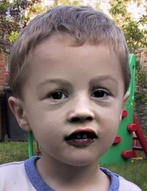
It may be helpful to think of the input image as a Digital Elevation Model (DEM), representing heights in a landscape, from a lowest level at 0% to a mountain at 100%. At any point on the landscape, the slope has a particular direction and magnitude.
Slopes of ordinary photographs are usually close to zero, and can be positive or negative.
In this context, literature often uses scalar or scalar field to mean ordinary images with one value per channel per pixel, and vector or vector field to mean two values per channel per pixel. The slope can also be regarded as a tensor field.
Slopes are a form of differentiation.
These slope methods are useful for
Seamless photomontage.
CAUTION: In v1.0 of this page, slope and div images were offset so zero was represented by pixel values of 50%.
If the range of input pixel values is 0 to 100%, then the range of slopes is -100% to +100%. Scripts to make a slope would divide by two and add 50% so the resulting values were in the range 0 to 100%, with 50% representing a zero slope. (Note that when we use the difference beween pixels on either side of a central pixel, the distance between them is two, so dividing by two is reasonable.)
However, the
Fifty percent problem created difficulties, and all this dividing and adding took time, so now zero slopes are represented by pixel values of 0%, and negative values are common, and HDRI should always be used.
On this page, we divide by two and add 50% purely to show the image.
The script
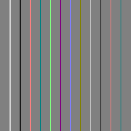
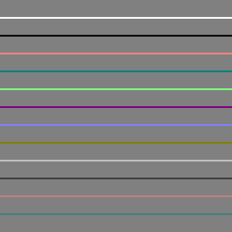
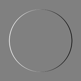
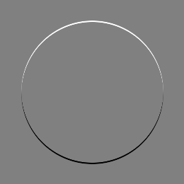
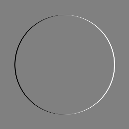
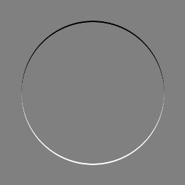
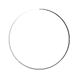
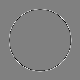
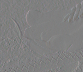
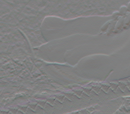
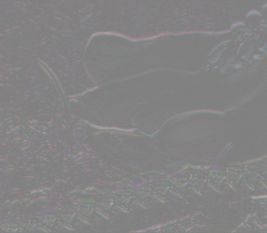
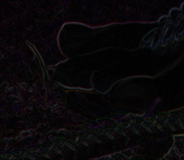
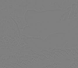
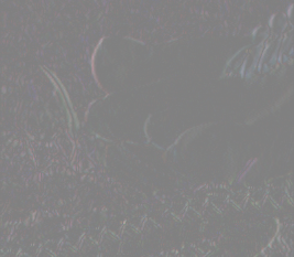
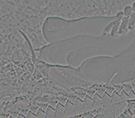
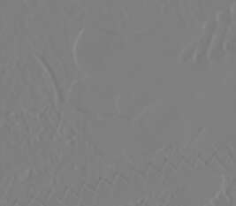
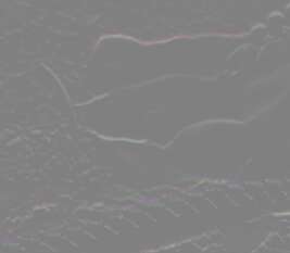
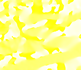
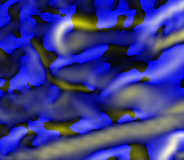
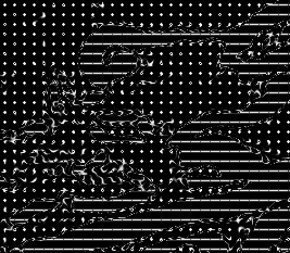
slopeXY.bat takes an input colour image and makes a vector. Each output pixel is the input pixel on the right (or below) minus the input pixel on the left (or above). Hence, a 3x3 rectangular window is used, but only four pixels participate, with all having the same weight.
Ẋ(x,y) = f(x+1,y) - f(x-1,y)
Ẏ(x,y) = f(x,y+1) - f(x,y-1)
... where f is the input image, and Ẋ and Ẏ are the slopes in the x-direction and y-direction.
Here, we store the outputs as single MIFF files, but convert them to a pair of PNG files for viewing on the web.
call %PICTBAT%slopeXY ^
  slp_src.png slp_sxy.miff

%IMG7%magick ^
  slp_sxy.miff[0] ^
  -evaluate Divide 2 ^
  -evaluate Add 50%% ^
  slp_sxy_0.png

%IMG7%magick ^
  slp_sxy.miff[1] ^
  -evaluate Divide 2 ^
  -evaluate Add 50%% ^
  slp_sxy_1.png
|

|
call %PICTBAT%slopeXY ^
  slp_src_h.png slp_h_sxy.miff

%IMG7%magick ^
  slp_h_sxy.miff[0] ^
  -evaluate Divide 2 ^
  -evaluate Add 50%% ^
  slp_h_sxy_0.png

%IMG7%magick ^
  slp_h_sxy.miff[1] ^
  -evaluate Divide 2 ^
  -evaluate Add 50%% ^
  slp_h_sxy_1.png
|

|
call %PICTBAT%slopeXY ^
  slp_src_vh.png slp_vh_sxy.miff

if ERRORLEVEL 1 goto error

%IMG7%magick ^
  slp_vh_sxy.miff[0] ^
  -evaluate Divide 2 ^
  -evaluate Add 50%% ^
  slp_vh_sxy_0.png

%IMG7%magick ^
  slp_vh_sxy.miff[1] ^
  -evaluate Divide 2 ^
  -evaluate Add 50%% ^
  slp_vh_sxy_1.png
|
|
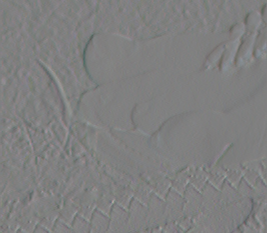
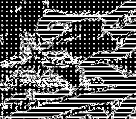
The slope images range from -100% to +100%. Horizontal slopes are positive when they increase to the right; vertical slopes are positive when they increase downwards.
The script
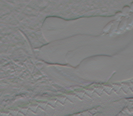
slopeXYneg.bat takes a vector as input, and creates a vector output, with each value becoming arithmetically negated (reflected around zero), so +10% becomes -10%, -20% becomes +20%, etc.
call %PICTBAT%slopeXYneg ^
  slp_vh_sxy.miff slp_vh_neg.miff

%IMG7%magick ^
  slp_vh_neg.miff[0] ^
  -evaluate Divide 2 ^
  -evaluate Add 50%% ^
  slp_vh_neg_0.png

%IMG7%magick ^
  slp_vh_neg.miff[1] ^
  -evaluate Divide 2 ^
  -evaluate Add 50%% ^
  slp_vh_neg_1.png
|
|
The script
slopeXYmean.bat takes a vector as input, and creates a vector output where each image is 1x1 pixels, the mean of the input. If the input is a slope ranging from -100% to +100%, the mean has the same range.
This measures how much the two sides differ, and how much the top and bottom differ. This is not usually of much interest.
call %PICTBAT%slopeXYmean ^
  slp_vh_sxy.miff slp_vh_mean.miff

%IMG7%magick ^
  slp_vh_mean.miff ^
  -format "%%[fx:r*100],%%[fx:g*100],%%[fx:b*100]\n" ^
  +write info: ^
  -evaluate Divide 2 ^
  -evaluate Add 50%% ^
  +append +repage ^
  -scale 200x100 ^
  slp_vh_mean.png
-4.58082e-16,-4.58082e-16,-4.58082e-16
-5.50417e-19,-5.50417e-19,-5.50417e-19
|

|
The script
slopeXYrms.bat takes a vector as input, and creates a vector output where each image is 1x1 pixels, the RMS (root mean square) of the input. If the input is a slope ranging from -100% to +100%, the RMS ranges from 0 to 100%.
This measures how much the slope varies from zero. If the mean is zero, the RMS is also the standard deviation.
call %PICTBAT%slopeXYrms ^
  slp_vh_sxy.miff slp_vh_rms.miff

%IMG7%magick ^
  slp_vh_rms.miff ^
  -format "%%[fx:r*100],%%[fx:g*100],%%[fx:b*100]\n" ^
  +write info: ^
  -evaluate Divide 2 ^
  -evaluate Add 50%% ^
  +append +repage ^
  -scale 200x100 ^
  slp_vh_rms.png
9.77383,9.77383,9.77383
9.77379,9.77379,9.77379
|

|
The script
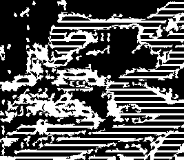
slopeXYabs.bat takes a vector as input, and creates a vector output, with each value becoming the absolute of the input, so +10% remains +10%, -20% becomes +20%, etc. If the input is a slope ranging from -100% to +100%, the absolute ranges from 0 to 100%. In each channel, we do:
if Ẋ <= 0 then Ẋ' = -Ẋ else Ẋ' = Ẋ
if Ẏ <= 0 then Ẏ' = -Ẏ else Ẏ' = Ẏ
call %PICTBAT%slopeXYabs ^
  slp_vh_sxy.miff slp_vh_abs.miff

%IMG7%magick ^
  slp_vh_abs.miff[0] ^
  -evaluate Divide 2 ^
  -evaluate Add 50%% ^
  slp_vh_abs_0.png

%IMG7%magick ^
  slp_vh_abs.miff[1] ^
  -evaluate Divide 2 ^
  -evaluate Add 50%% ^
  slp_vh_abs_1.png
|


|
The script
slopeXYmag.bat takes a vector as input, and creates a scalar output, the magnitude of the vector. If the input is a slope ranging from -100% to +100%, the magnitute ranges from 0 to 100%. (It would range up to 141.421...%, but we divide by two before taking the square root.) In each channel, we do:
mag = sqrt ((Ẋ2 + Ẏ2)/2)
call %PICTBAT%slopeXYmag ^
  slp_vh_sxy.miff slp_vh_mag.png
|
|
The direction is an angle, the arctangent of the two slopes. For methods of calculating arctan from a pair of images, see
Gradients Cookbook: arctan. The script
slopeXYdirn.bat takes a vector as input, and creates a scalar output, the direction of the vector. This uses
process module: arctan2. In each channel, we do:
dirn = atan2 (Ẋ, Ẏ) + addmod
When SWAP is given, Ẋ and Ẏ are interchanged. On this page we commonly use SWAP . 75 and the formula boils down to:
dirn = atan2 (Ẋ, -Ẏ)
... where dirn is like a compass bearing of the downward slope.
Where the x- and y-slopes are both zero, the magnitude is zero, and the direction is indeterminate.
|
Make a direction image.
call %PICTBAT%slopeXYdirn ^
  slp_vh_sxy.miff slp_vh_dirn.png ^
  SWAP . 75
|

|
|
In the direction image,
make transparent where magnitude is zero.
%IMG7%magick ^
  slp_vh_mag.png ^
  -fill White +opaque Black ^
  slp_vh_dirn.png ^
  +swap ^
  -compose CopyOpacity -composite ^
  slp_vh_dirn_tr.png
|
|
In the direction image, we could use the alpha channel to represent magnitude, but that couldn't represent all three magnitudes.
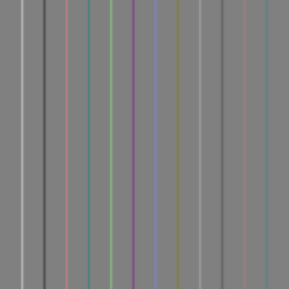
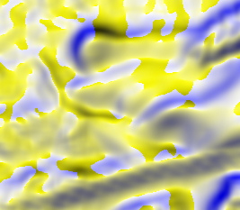
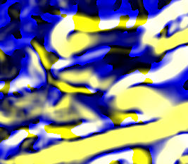
The direction is recorded as a value from 0% to 100%. When we use "SWAP . 75", 0% and 100% represent a downward slope to the north, and values increase as the slope changes angle clockwise. The edge (or contour) is perpendicular to the slope, so we can regard the direction value as representing edge directions to the east (0%), clockwise to south (25%), west (50%), north (75%) and east again (100%). As we walk along the direction of the edge, pixels to the right are lighter than pixels on the left.
The script
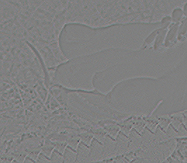
slopeXYdiv.bat takes a vector as input, and creates a scalar output, the divergence (aka div) of the vector. The input for divergence is usually a slope, and the divergence takes the slope of this slope, then adds the two components. If the original input ranges from 0 to 100%, so the slope ranges from -100% to +100%, output divergence values will range from -50% to +50%. Values of 0% represent zero divergence.
See
Wikipedia: divergence.
call %PICTBAT%slopeXYdiv ^
  slp_vh_sxy.miff slp_vh_div.miff

if ERRORLEVEL 1 goto error

%IMG7%magick ^
  slp_vh_div.miff ^
  -evaluate Add 50%% ^
  slp_vh_div.png
|
|
The script
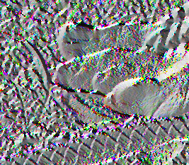
shpDiv.bat takes an image as input, and directly makes a divergence of the slope. This is also sharper than slopeXYdiv.bat, with just one pixel on each side of an cliff-edge. The range is as for slopeXYdiv.bat, but for ordinary photographs values are closer to zero.
call %PICTBAT%shpDiv ^
  slp_src_vh.png slp_vh_shpdiv.miff

%IMG7%magick ^
  slp_vh_shpdiv.miff ^
  -evaluate Add 50%% ^
  slp_vh_shpdiv.png
|
|
Normalise slopes so y (or x??) component is positive, so 0 <= direction <= 180 deg. Then averaging, by "-scale", is meaningful??
For some purposes, we want to treat slopes at x° and (x+180)° as the same.
In each channel, we do:
if Ẋ < 0 then
  Ẋ' = -Ẋ
  Ẏ' = -Ẏ
else
  Ẋ' = Ẋ
  Ẏ' = Ẏ
endif

if Ẋ < 0 then Ẏ' = -Ẏ else Ẏ' = Ẏ
call %PICTBAT%slopeXYposang ^
  slp_vh_sxy.miff slp_vh_pa.miff

%IMG7%magick ^
  slp_vh_pa.miff[0] ^
  -evaluate Divide 2 ^
  -evaluate Add 50%% ^
  slp_vh_pa_0.png

%IMG7%magick ^
  slp_vh_pa.miff[1] ^
  -evaluate Divide 2 ^
  -evaluate Add 50%% ^
  slp_vh_pa_1.png
|

|
call %PICTBAT%slopeXYdirn ^
  slp_vh_pa.miff slp_vh_pa_dirn.miff ^
  SWAP . 75

%IMG7%magick ^
  slp_vh_pa_dirn.miff ^
  slp_vh_pa_dirn.png
|

|
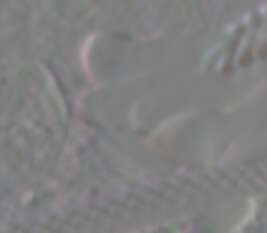
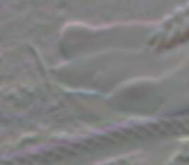
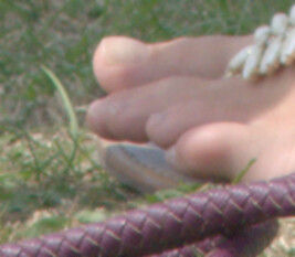
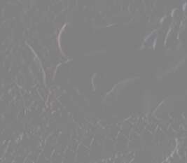
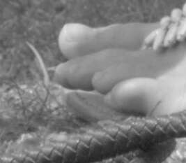
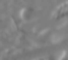
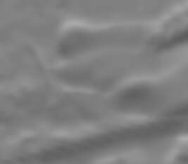
The same operations on toes.png:
call %PICTBAT%slopeXY ^
  toes.png slp_toes_sxy.miff

%IMG7%magick ^
  slp_toes_sxy.miff[0] ^
  -evaluate Divide 2 ^
  -evaluate Add 50%% ^
  slp_toes_sxy_0.png

%IMG7%magick ^
  slp_toes_sxy.miff[1] ^
  -evaluate Divide 2 ^
  -evaluate Add 50%% ^
  slp_toes_sxy_1.png
|
|
call %PICTBAT%slopeXYneg ^
  slp_toes_sxy.miff slp_toes_neg.miff

%IMG7%magick ^
  slp_toes_neg.miff[0] ^
  -evaluate Divide 2 ^
  -evaluate Add 50%% ^
  slp_toes_neg_0.png

%IMG7%magick ^
  slp_toes_neg.miff[1] ^
  -evaluate Divide 2 ^
  -evaluate Add 50%% ^
  slp_toes_neg_1.png
|
|
call %PICTBAT%slopeXYmean ^
  slp_toes_sxy.miff slp_toes_mean.miff

%IMG7%magick ^
  slp_toes_mean.miff ^
  -format "%%[fx:r*100],%%[fx:g*100],%%[fx:b*100]\n" ^
  +write info: ^
  -evaluate Divide 2 ^
  -evaluate Add 50%% ^
  +append +repage ^
  -scale 200x100 ^
  slp_toes_mean.png
0.216085,0.137083,0.188127
0.025961,-0.0926699,0.0056107
|

|
call %PICTBAT%slopeXYrms ^
  slp_toes_sxy.miff slp_toes_rms.miff

%IMG7%magick ^
  slp_toes_rms.miff ^
  -format "%%[fx:r*100],%%[fx:g*100],%%[fx:b*100]\n" ^
  +write info: ^
  -evaluate Divide 2 ^
  -evaluate Add 50%% ^
  +append +repage ^
  -scale 200x100 ^
  slp_toes_rms.png
4.42872,3.46877,4.18751
5.23035,4.33608,4.97073
|

|
call %PICTBAT%slopeXYabs ^
  slp_toes_sxy.miff slp_toes_abs.miff

%IMG7%magick ^
  slp_toes_abs.miff[0] ^
  -evaluate Divide 2 ^
  -evaluate Add 50%% ^
  slp_toes_abs_0.png

%IMG7%magick ^
  slp_toes_abs.miff[1] ^
  -evaluate Divide 2 ^
  -evaluate Add 50%% ^
  slp_toes_abs_1.png
|

|
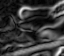
call %PICTBAT%slopeXYmag ^
  slp_toes_sxy.miff slp_toes_mag.png
|
|
call %PICTBAT%slopeXYdirn ^
  slp_toes_sxy.miff slp_toes_dirn.png ^
  SWAP . 75
|
|
call %PICTBAT%slopeXYdiv ^
  slp_toes_sxy.miff slp_toes_div.miff

%IMG7%magick ^
  slp_toes_div.miff ^
  -evaluate Add 50%% ^
  slp_toes_div.png
|
|
call %PICTBAT%shpDiv ^
  toes.png slp_toes_shpdiv.miff

%IMG7%magick ^
  slp_toes_shpdiv.miff ^
  -evaluate Add 50%% ^
  slp_toes_shpdiv.png
|
|
call %PICTBAT%slopeXYposang ^
  slp_toes_sxy.miff slp_toes_pa.miff

%IMG7%magick ^
  slp_toes_pa.miff[0] ^
  -evaluate Divide 2 ^
  -evaluate Add 50%% ^
  slp_toes_pa_0.png

%IMG7%magick ^
  slp_toes_pa.miff[1] ^
  -evaluate Divide 2 ^
  -evaluate Add 50%% ^
  slp_toes_pa_1.png
|
|
call %PICTBAT%slopeXYdirn ^
  slp_toes_pa.miff slp_toes_pa_dirn.miff ^
  SWAP . 75

%IMG7%magick ^
  slp_toes_pa_dirn.miff ^
  slp_toes_pa_dirn.png
|
|
To aid visibility, the script
autoLevMid.bat adds 50% then expands the range of values so the lightest is 100% or the darkest is 0%, or both. So it works like "-auto-level" but keeps 50% at 50%.
call %PICTBAT%autoLevMid ^
  slp_toes_div.miff slp_td_alm.png 1
|
|
The script
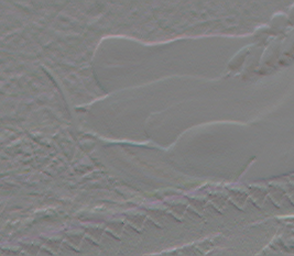
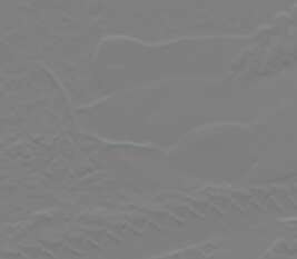
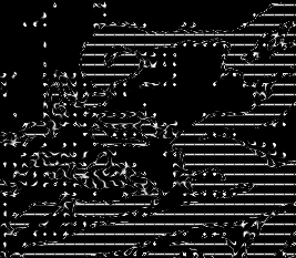
slopeXYbl.bat uses a Nx1 window with Guassian weighting. Hence pixels that are further from the pixel in question can participate in the slope calculation, but they contribute less weight. Instead of window size, the script takes a blur sigma, and IM automatically calculates the window size in the usual way.
For example, with sigma=1:
call %PICTBAT%slopeXYbl ^
  slp_src.png slp_sxybl.miff 1

%IMG7%magick ^
  slp_sxybl.miff[0] ^
  -evaluate Divide 2 ^
  -evaluate Add 50%% ^
  slp_sxybl_0.png

%IMG7%magick ^
  slp_sxybl.miff[1] ^
  -evaluate Divide 2 ^
  -evaluate Add 50%% ^
  slp_sxybl_1.png
|

|
call %PICTBAT%slopeXYbl ^
  toes.png slp_toesbl.miff 1

%IMG7%magick ^
  slp_toesbl.miff[0] ^
  -evaluate Divide 2 ^
  -evaluate Add 50%% ^
  slp_toesbl_0.png

%IMG7%magick ^
  slp_toesbl.miff[1] ^
  -evaluate Divide 2 ^
  -evaluate Add 50%% ^
  slp_toesbl_1.png
|
|
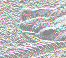
For example, with a larger sigma:
call %PICTBAT%slopeXYbl ^
  slp_src.png slp_sxybl.miff 5

%IMG7%magick ^
  slp_sxybl.miff[0] ^
  -evaluate Divide 2 ^
  -evaluate Add 50%% ^
  slp_sxybl2_0.png

%IMG7%magick ^
  slp_sxybl.miff[1] ^
  -evaluate Divide 2 ^
  -evaluate Add 50%% ^
  slp_sxybl2_1.png
|


|
call %PICTBAT%slopeXYbl ^
  toes.png slp_toesbl2.miff 5

%IMG7%magick ^
  slp_toesbl2.miff[0] ^
  -evaluate Divide 2 ^
  -evaluate Add 50%% ^
  slp_toesbl2_0.png

%IMG7%magick ^
  slp_toesbl2.miff[1] ^
  -evaluate Divide 2 ^
  -evaluate Add 50%% ^
  slp_toesbl2_1.png
|
|
When calculating the slope, the script doesn't divide by the distance between the pixels on each side. So a larger sigma may give slope values that are over-large. Beware of mixing results when different sigmas are used. I may correct this (when I figure out how).
Given the definition of slope, we cannot reconstruct the original image from the slope with no other data.
If we know the colours around the edges of the image, we can calculate the divergence, then use
Guided gradients.
|
Make a hollow version, with opaque edges.
call %PICTBAT%hollowEdge ^
  toes.png slp_toes_hlw.png
|

|
|
Relax-fill with guidance.
call %PICTBAT%relaxFillMS ^
  slp_toes_hlw.png . slp_toes_hlw_r.png ^
  0.0001 1000 . slp_toes_div.miff
|
|
How accurate is the round-trip?
%IMG7%magick compare -metric RMSE ^
  toes.png slp_toes_hlw_r.png NULL:
499.302 (0.00761886)
It is quite accurate.
We can even do this knowing the colour of just one pixel, though convergence is very slow, and numeric stability is a problem.
Inverting the calculation from slope to magnitude and direction is easier. If the slopes are Ẋ and Ẏ then:
mag =  sqrt (Ẋ2 + Ẏ2) / sqrt(2)
dirn = atan (Ẋ, Ẏ)
So:
Ẋ = mag * sqrt(2) * cos(dirn)
Ẏ = mag * sqrt(2) * sin(dirn)
The ranges of values, as percentages of quantum, are:
-100% <= Ẋ, Ẏ <= +100%
0 <= mag <= 100%
0 <= dirn <= 100%
To calculate Ẋ and Ẏ from mag and dirn, we use -function Sinusoid freq,phase,amp,bias where freq=1, phase=90-75% for Ẋ and phase=0-75% for Ẏ, amp=1, and bias=0. We implement this in the script
slopeMD2XY.bat.
As above, to see these images, we need to divide by 2 and add 50%.
call %PICTBAT%slopeMD2XY ^
  slp_toes_mag.png ^
  slp_toes_dirn.png ^
  slp_toes_calcxy.miff

%IMG7%magick ^
  slp_toes_calcxy.miff[0] ^
  -evaluate Divide 2 ^
  -evaluate Add 50%% ^
  slp_toes_calcx.png

%IMG7%magick ^
  slp_toes_calcxy.miff[1] ^
  -evaluate Divide 2 ^
  -evaluate Add 50%% ^
  slp_toes_calcy.png
|
|
How accurate is the round-trip?
%IMG7%magick compare -metric RMSE ^
  slp_toes_sxy.miff[0] slp_toes_calcxy.miff[0] NULL:
1743.53 (0.0266046)
%IMG7%magick compare -metric RMSE ^
  slp_toes_sxy.miff[1] slp_toes_calcxy.miff[1] NULL:
2091.56 (0.0319152)
The round-trip from slope to magnitude and direction, and back, is accurate.
From the slopes within a given area, we can obtain the average slope direction and magnitude.
We can make anglegrams. An anglegram is a Nx1 image (eg 360x1) where each pixel represents a bin of slope angles, and each pixel value represents a count of slopes in that bin, each count weighted by the slope magnitude. Counts are normalised. The anglegram is then graphed and polar-distorted so the angle repesents the slope direction, and the radius represents the slope magnitude.
Blah.
Slopes can be used for selective blur and sharpening. Blurring in a direction perpendicular to the slope (that is, parallel to the edge) de-emphasises non-edge detail. We then sharpen edges, by an unsharp mask made from a blur along the slope (that is, perpendicular to the edge).
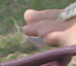
|
A source image, toes.png.
set BS_SRC=toes.png

set BLUR_SIG1=10
set BLUR_SIG2=5
|

|
|
Make a grayscale version.
%IMG7%magick ^
  %BS_SRC% ^
  -colorspace Gray ^
  slp_bs_gr.png
|
|
|
Get the slopes of the grayscale version.
call %PICTBAT%slopeXYbl ^
  slp_bs_gr.png slp_bs_sxy.miff %BLUR_SIG1%

%IMG7%magick ^
  slp_bs_sxy.miff[0] ^
  -evaluate Divide 2 ^
  -evaluate Add 50%% ^
  slp_bs_sxy_0.png

%IMG7%magick ^
  slp_bs_sxy.miff[1] ^
  -evaluate Divide 2 ^
  -evaluate Add 50%% ^
  slp_bs_sxy_1.png
|
|
|
Get the slope direction of the grayscale version.
call %PICTBAT%slopeXYdirn ^
  slp_bs_sxy.miff slp_bs_dirn.png ^
  SWAP . 75
|
|
|
Put the direction in a blue channel for a mask.
%IMG7%magick ^
  slp_bs_dirn.png ^
  ( +clone -fill White -colorize 100 ) ^
  ( +clone ) ^
  -swap 0,2 ^
  -combine ^
  slp_bs_msk.png
|

|
|
Blur with the directional mask.
%IMG7%magick ^
  %BS_SRC% ^
  slp_bs_msk.png ^
  -compose Blur ^
  -set option:compose:args ^
    %BLUR_SIG2%x0+0+360 ^
  -composite ^
  slp_bs_blr.png
|

|
We can sharpen the previous result through conventional processing, or by blurring it in the perpendicular direction and using that as an unsharp mask (ie blur, but extrapolate in the opposite direction).
|
Sharpen with an unsharp mask.
%IMG7%magick ^
  slp_bs_blr.png ^
  ( +clone ^
    slp_bs_msk.png ^
    -compose Blur ^
    -set option:compose:args ^
      0x%BLUR_SIG2%+0+360 ^
    -composite ^
  ) ^
  +swap ^
  -compose blend ^
    -define compose:args=150 ^
  -composite ^
  slp_bs_blr_sh.png
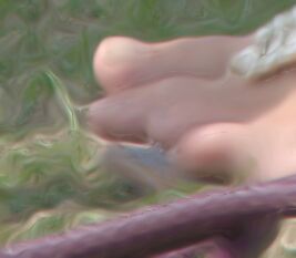
|
|
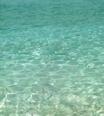
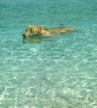
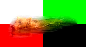
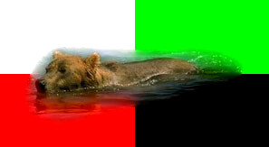
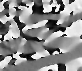
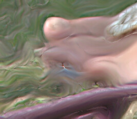
We put this in a script
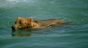
contourBlrShp.bat. At large values, the effect is like diffraction through water.
call %PICTBAT%contourBlrShp ^
  %BS_SRC% slp_bss.png
|
|
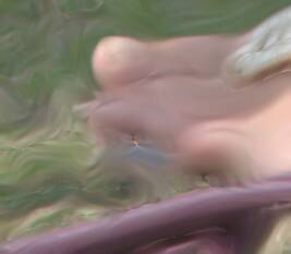
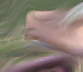
call %PICTBAT%contourBlrShp ^
  %BS_SRC% slp_bss2.png 20
|
|
call %PICTBAT%contourBlrShp ^
  %BS_SRC% slp_bss2a.png 20 . . 300
|
|
call %PICTBAT%contourBlrShp ^
  %BS_SRC% slp_bss3.png 50
|
|
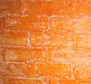
A related effect is to use a two-dimensional blur, modulating the radius by the stretched negated slope magnitude. Hence we get more blur where the slope is lowest. The "-contrast-stretch" puts a proportion of the pixels at zero blur, and another larger proportion at maximum blur.
|
Calculate the magnitude.
call %PICTBAT%slopeXYmag ^
  slp_bs_sxy.miff slp_bs_mag.png ^
  AUTOLEV
|
|
|
Put the stretched negated magnitude in the red and green channels for a mask.
%IMG7%magick ^
  slp_bs_mag.png ^
  -negate ^
  -contrast-stretch 20%%x30%% ^
  -channel B -evaluate set 100%% +channel ^
  slp_bs_msk2.png
|
|
|
2D blur with the modulating mask.
%IMG7%magick ^
  %BS_SRC% ^
  slp_bs_msk2.png ^
  -compose Blur ^
  -set option:compose:args ^
    %BLUR_SIG2%x%BLUR_SIG2%+0+360 ^
  -composite ^
  slp_bs_blr2.png
|

|
We put this is a script, adapBlrShp.bat. See
Adaptive blur and sharpen.
We can combine these effects, to get a one-dimensional blur that is angled to be perpendicular to the slope (ie parallel to the edge) and with the blur size inversely proportional to the slope magnitude (so we get most blurring where the image is least sharp).
We make a mask with the negated magnitude in the red and green channels, and the direction in the blue channel.
|
Make a mask.
%IMG7%magick ^
  slp_bs_mag.png -negate ^
  ( +clone ) ^
  slp_bs_dirn.png ^
  -combine ^
  slp_bs_msk2.png
|
|
|
Blur with the directional mask.
%IMG7%magick ^
  %BS_SRC% ^
  slp_bs_msk2.png ^
  -compose Blur ^
  -set option:compose:args ^
    %BLUR_SIG2%x0+0+360 ^
  -composite ^
  slp_bs_blr2.png
|
|
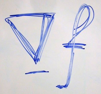
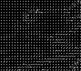
We can represent countour of equal slope, which are lines perpendicular to slope directions, by applying the blur mask to a grid of dots.
|
Create a grid of dots.
%IMG7%magick ^
  %BS_SRC% ^
  ( -size 1x1 xc:White ^
    -gravity Center ^
    -bordercolor Black -border 4 ^
    -write mpr:TILE +delete ^
  ) ^
  -tile mpr:TILE -draw "color 0,0 reset" ^
  slp_vs_src.png
|

|
First, we consider direction only, without magnitude.
|
Make a mask.
%IMG7%magick ^
  slp_bs_dirn.png ^
  ( +clone -evaluate set 100%% ) ^
  ( +clone ) ^
  -swap 0,2 ^
  -combine ^
  slp_vs_msk.png
|
|
|
Blur it with the directional mask.
%IMG7%magick ^
  slp_vs_src.png ^
  slp_vs_msk.png ^
  -compose Blur ^
  -set option:compose:args ^
    %BLUR_SIG2%x0+0+360 ^
  -composite ^
  -auto-level ^
  slp_vs_blr.png
|

|
Then, we consider direction and magnitude together. We need a heavy "-sigmoidal-contrast" to show the blurred dots.
|
Make a mask.
%IMG7%magick ^
  slp_bs_mag.png ^
  ( +clone ) ^
  slp_bs_dirn.png ^
  -combine ^
  slp_vs_msk2.png
|
|
|
Blur it with the directional mask.
%IMG7%magick ^
  slp_vs_src.png ^
  slp_vs_msk2.png ^
  -compose Blur ^
  -set option:compose:args ^
    %BLUR_SIG2%x0+0+360 ^
  -composite ^
  -auto-level ^
  -sigmoidal-contrast 20,10% ^
  slp_vs_blr2.png
|
|
By stretching the magnitude, we emphasise steep slopes and de-emphasise shallow slopes.
|
Make a mask.
%IMG7%magick ^
  slp_bs_mag.png ^
  -contrast-stretch 20%%x30%% ^
  ( +clone ) ^
  slp_bs_dirn.png ^
  -combine ^
  slp_vs_msk3.png
|
|
|
Blur it with the directional mask.
%IMG7%magick ^
  slp_vs_src.png ^
  slp_vs_msk3.png ^
  -compose Blur ^
  -set option:compose:args ^
    %BLUR_SIG2%x0+0+360 ^
  -composite ^
  -auto-level ^
  -sigmoidal-contrast 20,10% ^
  slp_vs_blr3.png
|
|
We can remove small marks, for example by using "-connected-components".
|
Threshold.
%IMG7%magick ^
  slp_vs_blr3.png ^
  -threshold 0 ^
  slp_vs_blr3_th.png
|
|
|
Find large components.
%IMG7%magick ^
  slp_vs_blr3_th.png ^
  -define connected-components:mean-color=true ^
  -define connected-components:area-threshold=20 ^
  -connected-components 4 ^
  slp_vs_blr3_lc.png
|
|
|
Black-out the others.
%IMG7%magick ^
  slp_vs_blr3.png ^
  slp_vs_blr3_lc.png ^
  -compose Darken -composite ^
  slp_vs_blr3_lge.png
|
|
Slope and divergence are important tools for
seamless photomontage. Some examples from that page:
A slope magnitude makes a useful saliency map for
Crop to detail.
|
Input
|
|
|
Output, automatically cropped
|
|
rem From colour image %1,
rem find slope of RGB channels.
rem Write output to _two_ images %2: first is x-slope, second is y-slope.
rem %3 is optional pre-process.
rem In output, 0% means no slope, > 0% value increases rightwards or downwards.
@rem Assumes IM is HDRI.
@rem
@rem Updated:
@rem   12-July-2022 Upgraded for IM v7.

@if "%1"=="" findstr /B "rem @rem" %~f0 & exit /B 1

@setlocal

@call echoOffSave

call %PICTBAT%setInOut %1 sxy

if not "%2"=="" set OUTFILE=%2

set PREPROC=%~3
if "%PREPROC%"=="." set PREPROC=

%IMG7%magick ^
  %INFILE% ^
  %PREPROC% ^
  -alpha off ^
  -virtual-pixel Edge ^
  ( -clone 0 -morphology Convolve 3x1:1,0,-1 ) ^
  ( -clone 0 -morphology Convolve 1x3:1,0,-1 ) ^
  -delete 0 ^
  +depth ^
  -depth 32 ^
  -define "quantum:format=floating-point" ^
  %OUTFILE%

if ERRORLEVEL 1 exit /B 1

call echoRestore

endlocal & set sxyOUTFILE=%OUTFILE%
rem From colour image %1,
rem find slope of RGB channels, by comet blur method.
rem Write output %2 to _two_ images: first is x-slope, second is y-slope.
rem %3 is (quoted) comma-list of one or two blur sigmas.
rem   First should be at least about 0.12.
rem   Second is orthogonal to first, default half of first
rem In output, 0% means no slope, > 0% value increases rightwards or downwards.
@rem
@rem Assumes magick is HDRI.
@rem
@rem See also slopeXYblMag.bat.
@rem
@rem Updated:
@rem   24-December-2017 %3 is one or two sigmas.
@rem   22-July-2022 Upgraded for IM v7.
@rem

@if "%1"=="" findstr /B "rem @rem" %~f0 & exit /B 1

@setlocal

@call echoOffSave

call %PICTBAT%setInOut %1 sxy

if not "%2"=="" set OUTFILE=%2

set BLR_SIG=%~3
call %UTIL%\parseCommaList "%BLR_SIG%" nSIG SIGS

if %nSIG%==0 (
  set BLR_SIG0=1
  set BLR_SIG1=0.5
) else if %nSIG%==1 (
  set BLR_SIG0=%SIGS[0]%

  for /F "usebackq" %%L in (`%IMG7%magick identify ^
    -format "BLR_SIG1=%%[fx:%SIGS[0]%/2]"
    xc:`) do set %%L

) else if %nSIG%==2 (
  set BLR_SIG0=%SIGS[0]%
  set BLR_SIG1=%SIGS[1]%
)

echo %0: BLR_SIG0=%BLR_SIG0% BLR_SIG1=%BLR_SIG1%

if %BLR_SIG1%==0 (
  set ORTHV=
  set ORTHH=
) else (
  set ORTHV=-morphology Convolve Blur:0x%BLR_SIG1%,90
  set ORTHH=-morphology Convolve Blur:0x%BLR_SIG1%
)

%IMG7%magick ^
  %INFILE% ^
  -alpha off ^
  -virtual-pixel Edge ^
  -define compose:clamp=off ^
  -define convolve:scale="^!" ^
  ( -clone 0 ^
    ( -clone 0 ^
      -morphology Convolve Comet:0x%BLR_SIG% ^
      %ORTHV% ^
    ) ^
    ( -clone 0 ^
      -morphology Convolve Comet:0x%BLR_SIG%,180 ^
      %ORTHV% ^
    ) ^
    -delete 0 ^
    -compose MinusDst -composite ^
  ) ^
  ( -clone 0 ^
    ( -clone 0 ^
      -morphology Convolve Comet:0x%BLR_SIG%,90 ^
      %ORTHH% ^
     ) ^
    ( -clone 0 ^
      -morphology Convolve Comet:0x%BLR_SIG%,270 ^
      %ORTHH% ^
    ) ^
    -delete 0 ^
    -compose MinusDst -composite ^
  ) ^
  -delete 0 ^
  +depth ^
  -depth 32 ^
  -define "quantum:format=floating-point" ^
  %OUTFILE%

if ERRORLEVEL 1 exit /B 1

call echoRestore

endlocal & set sxyOUTFILE=%OUTFILE%
rem Given %1 and %2 are slopeXY structures (thus contain 2 images each)
rem returns %3 a slopeXY structure, each channel is half (%2 minus %1.)
@rem
@rem Assumes magick is HDRI.
@rem
@rem Updated:
@rem   25-June-2017 Removed 50% bias.
@rem   22-July-2022 Upgraded for IM v7.


@if "%2"=="" findstr /B "rem @rem" %~f0 & exit /B 1

@setlocal

@call echoOffSave

call %PICTBAT%setInOut %1 sxyd

if not "%3"=="" if not "%3"=="." set OUTFILE=%3

set IN_A=%INFILE%
set IN_B=%2

%IMG7%magick ^
  -define compose:clamp=off ^
  ( %IN_A%[0] ^
    %IN_B%[0] ^
    -compose Mathematics -define compose:args=0,0.5,-0.5,0 -composite ^
  ) ^
  ( %IN_A%[1] ^
    %IN_B%[1] ^
    -compose Mathematics -define compose:args=0,0.5,-0.5,0 -composite ^
  ) ^
  +depth ^
  -depth 32 ^
  -define "quantum:format=floating-point" ^
  %OUTFILE%


call echoRestore

endlocal & set sxydOUTFILE=%OUTFILE%
rem Given %1 and %2 are slopeXY structures (thus contain 2 images each)
rem write weighted output %3 a slopeXY structure.
rem %4 is w1, floating-point weight (typically 0 to 1).
rem %5 is w2, floating-point weight (typically 0 to 1).
rem
rem Output each channel is w1 * %1 + w2 * %2
@rem
@rem Updated:
@rem   22-July-2022 Upgraded for IM v7.
@rem

@if "%2"=="" findstr /B "rem @rem" %~f0 & exit /B 1

@setlocal

@call echoOffSave

call %PICTBAT%setInOut %1 sxyw

if not "%3"=="" if not "%3"=="." set OUTFILE=%3

set WT1=%4
if "%WT1%"=="." set WT1=
if "%WT1%"=="" set WT1=0.5

set WT2=%5
if "%WT2%"=="." set WT2=

if "%WT2%"=="" for /F "usebackq" %%L in (`%IMG7%magick identify ^
  -format "WT2=%%[fx:1-%WT1%]" ^
  xc:`) do set %%L

set IN_A=%INFILE%
set IN_B=%2


%IMG7%magick ^
  ( %IN_A%[0] ^
    %IN_B%[0] ^
    -compose Mathematics -define compose:args=0,%WT2%,%WT1%,-0.5 -composite ^
  ) ^
  ( %IN_A%[1] ^
    %IN_B%[1] ^
    -compose Mathematics -define compose:args=0,%WT2%,%WT1%,-0.5 -composite ^
  ) ^
  +depth ^
  %OUTFILE%


call echoRestore

endlocal & set sxywOUTFILE=%OUTFILE%
rem Given %1 is slopeXY structure (thus contains 2 images),
rem returns %2 conventional RGB image
rem with channels set to magnitude.
rem %3 if AUTOLEV, auto-levels the output.
@rem
@rem Assumes magick is HDRI.
@rem
@rem Updated:
@rem   25-June-2017 Removed 50% bias
@rem   22-July-2022 Upgraded for IM v7.
@rem   26-July-2022 Replace "-evaluate Pow 2 -compose plus -composite -evaluate Divide 2 -evaluate Pow 0.5" by "-fx sqrt((u*u+v*v)/2)"
@rem

@if "%2"=="" findstr /B "rem @rem" %~f0 & exit /B 1

@setlocal

@call echoOffSave

call %PICTBAT%setInOut %1 sxym

if not "%2"=="" set OUTFILE=%2

set AUTOLEV=%3
if /I "%AUTOLEV%"=="AUTOLEV" (
  set sAUTOLEV=-auto-level
) else (
  set sAUTOLEV=
)

goto skip

%IMG7%magick ^
  %INFILE% ^
  -channel RGB ^
  -evaluate Pow 2 ^
  -separate ^
  -define compose:clamp=off ^
  ( -clone 0,3 -compose plus -composite ) ^
  ( -clone 1,4 -compose plus -composite ) ^
  ( -clone 2,5 -compose plus -composite ) ^
  -delete 0-5 ^
  -evaluate Divide 2 ^
  -evaluate Pow 0.5 ^
  -combine ^
  %sAUTOLEV% ^
  +depth ^
  -depth 32 ^
  -define "quantum:format=floating-point" ^
  %OUTFILE%

%IMG7%magick ^
  %INFILE% ^
  -channel RGB ^
  -evaluate Pow 2 ^
  -define compose:clamp=off ^
  -compose plus -composite ^
  -evaluate Divide 2 ^
  -evaluate Pow 0.5 ^
  %sAUTOLEV% ^
  +depth ^
  -depth 32 ^
  -define "quantum:format=floating-point" ^
  %OUTFILE%

:skip

%IMG7%magick ^
  %INFILE% ^
  -channel RGB ^
  -fx "sqrt((u*u+v*v)/2)" ^
  %sAUTOLEV% ^
  +depth ^
  -depth 32 ^
  -define "quantum:format=floating-point" ^
  %OUTFILE%

if ERRORLEVEL 1 exit /B 1

call echoRestore

endlocal & set sxymOUTFILE=%OUTFILE%
rem Given %1 is slopeXY structure (thus contains 2 images),
rem returns %2 conventional RGB image
rem with each channel set to direction.
rem %3 if SWAP, swap the two inputs.
rem %4 if SUB, subtract 50% before taking the arctan.
rem %5 percentage for addmodulus.
@rem
@rem Updated:
@rem   5-August-2022 for IM v7.
@rem

@if "%2"=="" findstr /B "rem @rem" %~f0 & exit /B 1

@setlocal

@call echoOffSave

call %PICTBAT%setInOut %1 sxyd

if not "%2"=="" set OUTFILE=%2

set SWAP=%3
if "%SWAP%"=="." set SWAP=
if "%SWAP%"=="" set SWAP=0

set SUBHALF=%4
if "%SUBHALF%"=="." set SUBHALF=
if "%SUBHALF%"=="" set SUBHALF=0

set nADDMOD=%5
if "%nADDMOD%"=="." set nADDMOD=
if "%nADDMOD%"=="" set nADDMOD=0

if /I "%SWAP%"=="SWAP" (
  set sSWAP=+swap
) else (
  set sSWAP=
)

if /I "%SUBHALF%"=="SUB" (
  set sSUBHALF=-evaluate Subtract 50%%
) else (
  set sSUBHALF=
)

echo %0: sSWAP=%sSWAP% sSUBHALF=%sSUBHALF% nADDMOD=%nADDMOD%

%IM7DEV%magick ^
  %INFILE% ^
  %sSWAP% ^
  %sSUBHALF% ^
  -process 'arctan2 b 0' ^
  -evaluate AddModulus %nADDMOD%%% ^
  +depth ^
  -depth 32 ^
  -define quantum:format=floating-point ^
  %OUTFILE%

if ERRORLEVEL 1 exit /B 1

call echoRestore

endlocal & set sxydOUTFILE=%OUTFILE%
rem Given %1 is slopeXY structure (thus contains 2 images)
rem returns %2 scalar image, the divergence of %1.
@rem
@rem The divergence of %1 is the x-slope of the x component,
@rem plus the y-slope of the y component.
@rem See Perez and https://en.wikipedia.org/wiki/Divergence.
@rem (Yeah, I think this is weird.)
@rem We find slope in the same way as slopeXY.bat.
@rem Assumes IM is HDRI.
@rem
@rem Updated:
@rem   25-June-2017 Removed bias 50%.
@rem   12-July-2022 Upgraded for IM v7.

@if "%1"=="" findstr /B "rem @rem" %~f0 & exit /B 1

@setlocal

@call echoOffSave

call %PICTBAT%setInOut %1 sxyd

if not "%2"=="" if not "%2"=="." set OUTFILE=%2

%IMG7%magick ^
  -define compose:clamp=off ^
  ( %INFILE%[0] ^
    -alpha off ^
    -morphology Convolve 3x1:0.5,0,-0.5 ^
  ) ^
  ( %INFILE%[1] ^
    -alpha off ^
    -morphology Convolve 1x3:0.5,0,-0.5 ^
  ) ^
  -compose Mathematics -define compose:args=0,0.5,0.5,0 -composite ^
  +depth ^
  -depth 32 ^
  -define "quantum:format=floating-point" ^
  %OUTFILE%

if ERRORLEVEL 1 (
  echo %0: Failed
  exit /B 1
)

call echoRestore

endlocal & set sxydOUTFILE=%OUTFILE%
rem From colour image %1,
rem returns %2 scalar image, the divergence of %1.
@rem
@rem Assumes magick is HDRI.
@rem
@rem Updated:
@rem   26-June-2017  Remove bias 50%
@rem   22-July-2022  Upgraded for IM v7.
@rem


@if "%1"=="" findstr /B "rem @rem" %~f0 & exit /B 1

@setlocal

@call echoOffSave

call %PICTBAT%setInOut %1 shd

if not "%2"=="" set OUTFILE=%2

%IMG7%magick ^
  %INFILE% ^
  -morphology Convolve 3x3:0,0.25,0,0.25,-1,0.25,0,0.25,0 ^
  -depth 32 -define quantum:format=floating-point ^
  %OUTFILE%

call echoRestore

endlocal & set shdOUTFILE=%OUTFILE%
rem Given %1 is slopeXY structure (thus contains 2 images),
rem outputs %2 slopeXY with values the arithmetic negative of the input values.
rem eg +10% becomes -10%; -20% becomes +20%.

call %PICTBAT%arithNeg %1 %2
An alternative is to clone, make that black, and subtract. However, when the input contains multiple images, that wouldn't work.
rem Given HDRI image %1,
rem makes %2 the arithmetic negative
rem eg +10% becomes -10%; -20% becomes +20%.
@rem
@rem Assumes magick is HDRI.
@rem
@rem Updated:
@rem   22-July-2022 Upgraded for IM v7.
@rem

rem Note: this works even if %1 has multiple images.

rem "Add 1" because 100% is QuantumRange+1.

%IMG7%magick ^
  %1 ^
  -channel RGB ^
  -negate -evaluate Subtract 100%% -evaluate Add 1 ^
  +channel ^
  %2
rem Given %1 is slopeXY structure (thus contains 2 images),
rem outputs %2 slopeXY structure, each image 1x1, the mean values.
rem Calculated by "-scale", so transparent input pixels don't count.
@rem
@rem Assumes magick is HDRI.
@rem
@rem Updated:
@rem   22-July-2022 Upgraded for IM v7.
@rem

%IMG7%magick ^
  %1 ^
  -scale "1x1%!" ^
  %2
rem Given %1 is slopeXY structure (thus contains 2 images),
rem outputs %2 slopeXY structure, each image 1x1, the RMS values.
rem Calculated by "-scale", so transparent input pixels don't count.
@rem
@rem Assumes magick is HDRI.
@rem
@rem Updated:
@rem   22-July-2022 Upgraded for IM v7.
@rem

%IMG7%magick ^
  %1 ^
  -channel RGB -evaluate Pow 2 +channel ^
  -scale "1x1%!" ^
  -channel RGB -evaluate Pow 0.5 +channel ^
  %2
rem Given %1 is slopeXY structure (thus contains 2 images),
rem outputs %2 slopeXY with values the absolute of the input values.

@call echoOffSave

rem FIXME: Now we can do this in one call, with all images.

rem (
rem   call %PICTBAT%absRGB %1[0] -
rem   call %PICTBAT%absRGB %1[1] -
rem ) >%2

call %PICTBAT%absRGB %1 %2

call echoRestore
rem Given HDRI image %1,
rem makes %2 with absolute image values in RGB channels.
@rem
@rem Assumes magick is HDRI.
@rem
@rem Updated:
@rem   22-July-2022 Upgraded for IM v7.
@rem

:: FIXME: What happens at zero?

%IMG7%magick ^
  %1 ^
  -define compose:clamp=off ^
  -evaluate Abs 0 ^
  -depth 32 ^
  -define "quantum:format=floating-point" ^
  %2
rem Makes auotolevel version, such that 50% remains at 50%.
rem Output %2 will have 0% or 100%, but generally not both.
rem %3 if not 0, will first add 50% to the image.
@rem
@rem Assumes magick is HDRI.
@rem
@rem Updated:
@rem   25-June-2017 Added "ADDHALF" facility.
@rem   22-July-2022 Upgraded for IM v7.
@rem

@if "%1"=="" findstr /B "rem @rem" %~f0 & exit /B 1

@setlocal

@call echoOffSave

call %PICTBAT%setInOut %1 alm

if not "%2"=="" if not "%2"=="." set OUTFILE=%2

set ADDHALF=%3
if "%ADDHALF%"=="." set ADDHALF=
if "%ADDHALF%"=="" set ADDHALF=0

if "%ADDHALF%"=="0" (
  set sADDHALF=
) else (
  set sADDHALF=-evaluate Add 50%%
)

for /F "usebackq" %%L in (`%IMG7%magick ^
  %INFILE% ^
  %sADDHALF% ^
  -format "dm=%%[fx:abs(minima-0.5)>abs(maxima)?minima:maxima]" ^
  info:`) do set %%L

echo %0: dm=%dm%

for /F "usebackq" %%L in (`%IMG7%magick identify ^
  -format "dm=%%[fx:100*(%dm%>0.5?1-%dm%:%dm%)]" ^
  xc:`) do set %%L

echo %0: dm=%dm%

for /F "usebackq" %%L in (`%IMG7%magick identify ^
  -format "dmo=%%[fx:100-%dm%]" ^
  xc:`) do set %%L

echo %0: dmo=%dmo%

%IMG7%magick ^
  %INFILE% ^
  %sADDHALF% ^
  -level %dm%,%dmo%%% ^
  %OUTFILE%


call echoRestore

endlocal & set almOUTFILE=%OUTFILE%&
rem Given %1 is magnitude
rem %2 is direction,
rem writes %3 a slopeXY structure.
@rem
@rem Assumes direction has been created with "SWAP . 75".
@rem
@rem Assumes magick is HDRI.
@rem
@rem Updated:
@rem   22-July-2022 Upgraded for IM v7.
@rem

@if "%3"=="" findstr /B "rem @rem" %~f0 & exit /B 1

@setlocal

@call echoOffSave

call %PICTBAT%setInOut %1 smdxy

set MAG=%1
set DIRN=%2
set OUTFILE=%3

%IMG7%magick ^
  %MAG% -evaluate Multiply 1.414213562373095 +write mpr:MAG +delete ^
  %DIRN% +write mpr:DIRN +delete ^
  -define compose:clamp=off ^
  ( mpr:DIRN -function Sinusoid 1,180,1,0 ^
    mpr:MAG ^
    -compose Multiply -composite ^
  ) ^
  ( mpr:DIRN -function Sinusoid 1,90,1,0 ^
    mpr:MAG ^
    -compose Multiply -composite ^
  ) ^
  +depth ^
  -depth 32 ^
  -define "quantum:format=floating-point" ^
  %OUTFILE%

call echoRestore

endlocal & set smdxyOUTFILE=%OUTFILE%
rem From image %1,
rem make %2 with all non-edge pixels transparent.
@rem
@rem Updated:
@rem   22-July-2022 Upgraded for IM v7.
@rem

%IMG7%magick ^
  %1 ^
  ( +clone ^
    -fill Black -colorize 100 ^
    -shave 1x1 ^
    -bordercolor White -border 1 ^
  ) ^
  -alpha off ^
  -compose CopyOpacity -composite ^
  -background White -alpha Background ^
  %2
rem From image %1,
rem makes output %2
rem blurred parallel to contours then sharpened perpendicular to contours.
rem %3 edge detector sigma
rem %4 blur sigma
rem %5 unsharp sigma
rem %6 percentage extrapolate for unsharp (100=no effect)
@rem
@rem Updated:
@rem   22-July-2022 Upgraded for IM v7.
@rem


@if "%1"=="" findstr /B "rem @rem" %~f0 & exit /B 1

@setlocal enabledelayedexpansion

rem @call echoOffSave

call %PICTBAT%setInOut %1 cbs

if not "%2"=="" if not "%2"=="." set OUTFILE=%2


set EDGE_SIG=%3
if "%EDGE_SIG%"=="." set EDGE_SIG=
if "%EDGE_SIG%"=="" set EDGE_SIG=10

set BLUR_SIG=%4
if "%BLUR_SIG%"=="." set BLUR_SIG=
if "%BLUR_SIG%"=="" set /A BLUR_SIG=%EDGE_SIG%/2

set UNSH_SIG=%5
if "%UNSH_SIG%"=="." set UNSH_SIG=
if "%UNSH_SIG%"=="" set /A UNSH_SIG=%BLUR_SIG%

set EXTR_PC=%6
if "%EXTR_PC%"=="." set EXTR_PC=
if "%EXTR_PC%"=="" set EXTR_PC=150

set TMPDIR=\temp\
set TMPGRAY=%TMPDIR%cbs_gray.miff
set TMPSLOPE=%TMPDIR%cbs_gray_slp.miff
rem set TMPMAG=%TMPDIR%cbs_gray_mag.miff

%IMG7%magick ^
  %INFILE% ^
  -colorspace Gray ^
  %TMPGRAY%

call %PICTBAT%slopeXYbl ^
  %TMPGRAY% %TMPGRAY% %EDGE_SIG%

call %PICTBAT%slopeXYdirn ^
  %TMPGRAY% %TMPSLOPE% ^
  SWAP . 75

rem call %PICTBAT%slopeXYmag ^
rem   %TMPGRAY% %TMPMAG%

%IMG7%magick ^
  %TMPSLOPE% ^
  ( +clone -fill White -colorize 100 ) ^
  ( +clone ) ^
  -swap 0,2 ^
  -combine ^
  %TMPSLOPE%

%IMG7%magick ^
  %INFILE% ^
  %TMPSLOPE% +write mpr:MASK ^
  -compose Blur ^
  -set option:compose:args %BLUR_SIG%x0+0+360 ^
  -composite ^
  ( +clone ^
    mpr:MASK ^
    -compose Blur ^
    -set option:compose:args 0x%UNSH_SIG%+0+360 ^
    -composite ^
  ) ^
  +swap ^
  -compose blend ^
    -define compose:args=%EXTR_PC% ^
  -composite ^
  %OUTFILE%


call echoRestore

@endlocal & set cbsOUTFILE=%OUTFILE%
All images on this page were created by the commands shown, using:
%IMG7%magick -version
Version: ImageMagick 7.1.1-15 Q16-HDRI x64 a0a5f3d:20230730 https://imagemagick.org
Copyright: (C) 1999 ImageMagick Studio LLC
License: https://imagemagick.org/script/license.php
Features: Cipher DPC HDRI OpenCL OpenMP(2.0)
Delegates (built-in): bzlib cairo freetype gslib heic jng jp2 jpeg jxl lcms lqr lzma openexr pangocairo png ps raqm raw rsvg tiff webp xml zip zlib
Compiler: Visual Studio 2022 (193532217)
To improve internet download speeds, some images may have been automatically converted (by ImageMagick, of course) from PNG or TIFF or MIFF to JPG.
Source file for this web page is slopes.h1. To re-create this web page, run "procH1 slopes".
This page, including the images, is my copyright. Anyone is permitted to use or adapt any of the code, scripts or images for any purpose, including commercial use.
Anyone is permitted to re-publish this page, but only for non-commercial use.
Anyone is permitted to link to this page, including for commercial use.
Page version v2.0 22-June-2017.
Page created 29-Sep-2023 08:14:34.
Copyright © 2023 Alan Gibson.