snibgo's ImageMagick pages
Radial distortions
Shape to shape, and rectangle to shape.
A radial distortion is a movement of pixels along each radius from a defined centre. (I am British, so I spell it "centre", not "center".) This is a specific case of
polar distortions; we are concerned only with ρ (rho), with no distortion of θ (theta).
On this page, we unroll images so what was (ρ,θ) becomes (x,y), and a distortion in the θ dimension becomes a distortion in the y dimension.
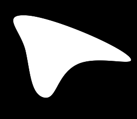
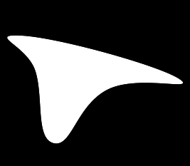
We create two sample masks using the
acwise program.
(
  echo 50,30
  echo 50,100
  echo 250,110
  echo 85,190
  echo 150,125
) | %IM7DEV%acwise ^
  -i - -o - ^
  --startat N -fmt curve | %IMG7%magick ^
  -size 267x233 xc:Black ^
  -fill White -stroke None ^
  -draw @- ^
  -alpha off ^
  rad_mask1.png
|
|
(
  echo 30,50
  echo 50,100
  echo 250,110
  echo 75,200
  echo 150,125
) | %IM7DEV%acwise ^
  -i - -o - ^
  --startat N -fmt curve | %IMG7%magick ^
  -size 267x233 xc:Black ^
  -fill White -stroke None ^
  -draw @- ^
  -alpha off ^
  rad_mask2.png
|
|
The script
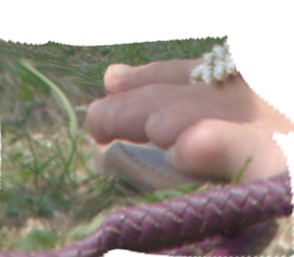
shp2shpRad.bat distorts an image so that one shape changes into another shape.
The input is an image that is to be distorted, and two masks, all the same size. Each mask should have one white shape on a black background. Some coordinate is declared to be the centre of the distortion. The centre should be white in both masks. The output will be a distorted version of the input, where pixels that were on the boundary of the first mask are moved along a radius from the centre to the boundary of the second mask. Other pixels are moved proportionally to their distance from the centre.
The overall process is:
- Unroll the image ("-distort DePolar").
- Distort in the vertical direction only with an absolute distortion map.
- Roll it back up ("-distort Polar").
The vertical distortion map is built from the two masks, unrolled, and a same-sized vertical gradient that is black at the top and white at the bottom. To make the mask:
- Scale each unrolled mask to a single row, so each pixel is the mean of the column in the unrolled mask.
- Divide the row of one mask by the row of the other mask.
- If the required effect percentage isn't 100, blend white with the previous result.
- Scale the previous result up to the same size as the gradient.
- Multiply the previous result by the gradient.
- The result is the required vertical distortion map.
In step two, where the columns in the two unrolled masks are equal, the result will be 1.0, so there will be no distortion along that radius. Hence if the two masks are equal, there will be no distortion.
If the input image is equal to the first mask, the result will be the second mask.
[ Is there mileage in allowing different centres for the two masks? ]
How does that work? Each value in the vertical gradient is equal to its y-coordinate as a proportion of the height minus one. So the vertical gradient is an identity displacement map; it defines a no-change displacement. But we want a displacement so that pixels that were on the edge of the first shape are moved to the edge of the second mask. Let v1 and v2 be the radial distances to the edges of the masks at the same value of θ. Then we need to divide each column of the gradient by v1, and multiply that by v2.
The script also has parameters for supersampling, and performing the work in an alternative colorspace, and setting the virtual-pixel for unrolling and rolling the main image, and for the percentage of the full effect. An effect of "0" will do no distortion; "100" will make the full effect; "-100" will reverse the effect (distorting from the second mask to the first).
call %PICTBAT%shp2shpRad ^
  toes.png rad_mask1.png rad_mask2.png ^
  rad_s2s.png 106x88
|
|
The script
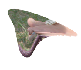
rect2shpRad.bat works in the same way as shp2shpRad above, but the first mask is the entire white rectangle. So we don't need to actually make the mask and unroll it, and the processing is slightly simpler. When we unroll the single mask, the white area at the top is the shape, then we have a black area which is area outside the shape, and the transparent area at the bottom is the virtual pixels. So the script first makes all opaque pixels white and flattens against black to get the white rectangle, then just flattens against black to get the white shape.
call %PICTBAT%rect2shpRad ^
  toes.png rad_mask1.png rad_r2s.png
|
|
|
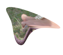
Reduce staircasing by supersampling:
call %PICTBAT%rect2shpRad ^
  toes.png rad_mask1.png rad_r2s2.png ^
  . 400
|
|
|
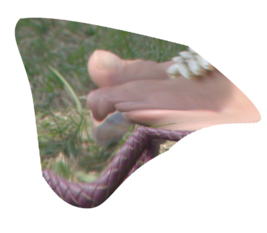
50% of effect:
call %PICTBAT%rect2shpRad ^
  toes.png rad_mask1.png rad_r2s3.png ^
  . 400 . 50
|
|
|
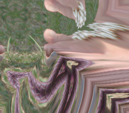
Virtual-pixel mirror, 100% of effect:
call %PICTBAT%rect2shpRad ^
  toes.png rad_mask1.png rad_r2s4.png ^
  . 400 mirror 100
|
|
|
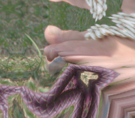
Virtual-pixel mirror, 50% of effect:
call %PICTBAT%rect2shpRad ^
  toes.png rad_mask1.png rad_r2s5.png ^
  . 400 mirror 50
|
|
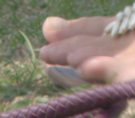
Test the round-trip:
|
Reverse the distortion "Virtual-pixel mirror, 100% of effect":
call %PICTBAT%rect2shpRad ^
  rad_r2s4.png rad_mask1.png rad_rev.png ^
  . 400 mirror -100
The result is fuzzy, especially on the right side which was heavily compressed.
|
|
We can reverse a 100% effect with a -100% effect. But this is not true of other percentages.
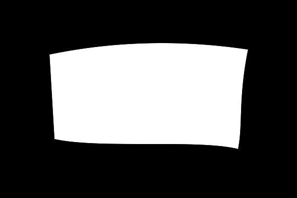
Suppose we have a mask with a shape that is approximately rectangular, and we want to distort a rectangular image to the shape.
|
A sample wonky rectangle:
set Wmask=600
set Hmask=400

set sPATH=^
M100,110 ^
C150,100 300,70 500,100 ^
C480,200 490,250 480,300 ^
C400,280 200,300 110,280 ^
z

%IMG7%magick ^
  -size %Wmask%x%Hmask% xc:Black ^
  -fill White -stroke None ^
  -draw "path '%sPath%'" ^
  rad_wonk_src.png
|
|
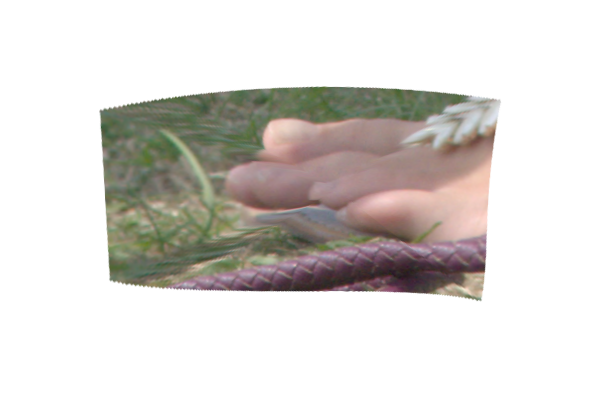
If we resize so they match sizes and then do a simple radial distortion, the result is poor near the diagonals. This is because the corresponding corners of the image and the shape are not on the same radius. (However, the result might be good enough for some purposes.)
%IMG7%magick ^
  toes.png ^
  -resize "%Wmask%x%Hmask%^!" ^
  rad_resiz.png

call %PICTBAT%rect2shpRad ^
  rad_resiz.png rad_wonk_src.png ^
  rad_wonk_bad.png
|
|
We constructed the sample artificially, so we know the corner coordinates. If we didn't know the corners, we would need to find them (see
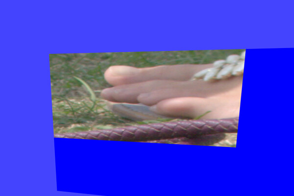
Finding the corners below). Then we can do a perspective distortion to move the image corners to the shape corners, and distort the result radially to the shape.
|
Perspective transformation.
We use a blue background to see more clearly what is happening.
set sPERSP=^
0,0,100,110 ^
%%[Wm1],0,500,100 ^
%%[Wm1],%%[Hm1],480,300 ^
0,%%[Hm1],110,280

%IMG7%magick ^
  toes.png ^
  -set option:Wm1 %%[fx:w-1] ^
  -set option:Hm1 %%[fx:h-1] ^
  -background Blue -virtual-pixel Background ^
  -extent %Wmask%x%Hmask% ^
  -background #44f -virtual-pixel Background ^
  -distort perspective "%sPERSP%" ^
  +repage ^
  rad_wonk_persp.png
|
|
|
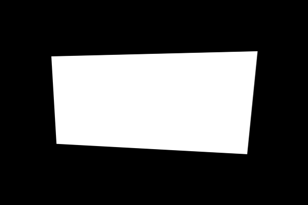
We also need a same-size "from" mask.
%IMG7%magick ^
  toes.png ^
  -fill White -colorize 100 ^
  -set option:Wm1 %%[fx:w-1] ^
  -set option:Hm1 %%[fx:h-1] ^
  -background Black ^
  -extent %Wmask%x%Hmask% ^
  -virtual-pixel Black ^
  -distort perspective "%sPERSP%" ^
  +repage ^
  rad_wonk_persp_msk.png
|
|
Now we can do the radial distortion, using two masks:
|
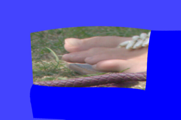
Distort the result radially to the shape.
call %PICTBAT%shp2shpRad ^
  rad_wonk_persp.png ^
  rad_wonk_persp_msk.png rad_wonk_src.png ^
  rad_wonk_good.png ^
  . . Edge
|
|
The result is good, with no obvious problems near the diagonals.
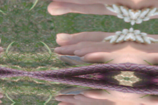
If we want the mirror effect, we can't simply change the -virtual-pixel setting in shp2shpRad, because pixels to the right and below are in the input image to that script, coming from -extent. So we need to replace -extent with a process that has the same effect, but with mirrored virtual-pixels. Such a process is -distort SRT 1,0 with a viewport and -virtual-pixel mirror, with -filter point to prevent any distortion of the image.
%IMG7%magick ^
  toes.png ^
  -set option:Wm1 %%[fx:w-1] ^
  -set option:Hm1 %%[fx:h-1] ^
  -define distort:viewport=%Wmask%x%Hmask% ^
  -virtual-pixel mirror ^
  -filter point ^
  -distort SRT 1,0 ^
  -distort perspective "%sPERSP%" ^
  +repage ^
  rad_wonk_persp2.png

call %PICTBAT%shp2shpRad ^
  rad_wonk_persp2.png ^
  rad_wonk_persp_msk.png rad_wonk_src.png ^
  rad_wonk_good2.png . . edge
|
|
A possible alternative method is:
- Do a perspective distortion on the mask to move the shape corners to the image corners.
- Distort the result radially to the distorted shape.
- Reverse the perspective distortion.
Above, we glibly said, "If we didn't know the corners [of the mask], we would need to find them." How do we do that?
Provided the the corners are close to the expected orientations, we can use -morphology HMT to find them, in the order: top-left, top-right, bottom-right, bottom-left, using the kernel:
0 0 0
0 1 -
0 - 1
set N=0

for /F "usebackq tokens=1,4,5 delims=(), " %%A in (`%IMG7%magick ^
  rad_wonk_src.png ^
  -virtual-pixel Black ^
  -colorspace Gray -alpha off ^
  -define "identify:limit=1" ^
  -define "identify:locate=maximum" ^
  ^( +clone ^
    -morphology HMT "3x3+1+1:0,0,0,0,1,-,0,-,1" ^
    +write info: ^
    +delete ^) ^
  ^( +clone ^
    -morphology HMT "3x3+1+1:0,0,0,-,1,0,1,-,0" ^
    +write info: ^
    +delete ^) ^
  ^( +clone ^
    -morphology HMT "3x3+1+1:1,-,0,-,1,0,0,0,0" ^
    +write info: ^
    +delete ^) ^
  ^( +clone ^
    -morphology HMT "3x3+1+1:0,-,1,0,1,-,0,0,0" ^
    +write info: ^
    +delete ^) ^
  NULL:`) do (
    if /I %%A==Gray: (
      set X[!N!]=%%B
      set Y[!N!]=%%C
      echo !N! %%B %%C
      set /A N+=1
    )
)

set X[
set Y[
X[0]=100
X[1]=500
X[2]=480
X[3]=110
Y[0]=110
Y[1]=100
Y[2]=300
Y[3]=280
This found the expected coordinates. A script could check that exactly four corners were found, and use them to build the environment variable sPERSP shown above.
We want to avoid a centre that can't "see" the entire boundary. A useful trick would be to find the set of all points that can see the entire boundary, and find the centre of those points.
We might find the centre from the intersection of two masks. This could guarantee the centre was contained within both white shapes.
For convenience, .bat scripts are also available in a single zip file. See
Zipped BAT files.
rem Radial distortion of image rectangle to shape.
rem
rem %1 input image to be distorted
rem %2 input mask: white shape on black background. Same size as %1.
rem %3 output file
rem %4 centre: CXxCY, or furthest or centroid or boundingbox.
rem      Assumes this is in white of mask, and can "see" entire shape boundary.
rem %5 supersample percentage [default: 100%, so no resampling]
rem %6 virtual-pixel setting [default None]
rem %7 percentage effect. Negative for reverse direction. [default 100]
@rem
@rem Also uses:
@rem   r2srColSpIn
@rem   r2srColSpOut

@if "%2"=="" findstr /B "rem @rem" %~f0 & exit /B 1

@setlocal enabledelayedexpansion

@call echoOffSave

call %PICTBAT%setInOut %1 r2sr

set MASK_FILE=%2

if not "%3"=="" if not "%3"=="." set OUTFILE=%3

set sCent=%4
if "%sCent%"=="" set sCent=.

call %PICTBAT%shpCent %MASK_FILE% %sCent% r2sr

if ERRORLEVEL 1 (
  echo %0: Error in shpCent. sCent=%sCent%
  exit /B 1
)

set RESAMP_PC=%5
if "%RESAMP_PC%"=="." set RESAMP_PC=
if "%RESAMP_PC%"=="" set RESAMP_PC=100

set VirtPix=%6
if "%VirtPix%"=="." set VirtPix=
if "%VirtPix%"=="" set VirtPix=None

rem FIXME: if VirtPixel is not set explicitly,
rem   perhaps we should use a more intelligent default.

set PC_Effect=%7
if "%PC_Effect%"=="." set PC_Effect=
if "%PC_Effect%"=="" set PC_Effect=100

set firstCh=%PC_Effect:~0,1%

if "%firstCh%"=="-" (
  set nEffect=%PC_Effect:~1%
  set DIVWHICH=DivideSrc
) else (
  set nEffect=%PC_Effect%
  set DIVWHICH=DivideDst
)

:: For "No displacement" we multiply by 1.0. So we blend between White and the divisor.

if "%nEffect%"=="100" (
  set sEffect=
) else (
  set sEffect= ^( +clone -fill White -colorize 100 ^) ^
    +swap -compose Blend -define compose:args=%nEffect% -composite +define compose:args
)

if %RESAMP_PC%==100 (
  set RESAMP_START=
  set RESAMP_END=
  set CX=%r2sr_CX%
  set CY=%r2sr_CY%
) else (
  set RESAMP_START=-resize %RESAMP_PC%%%
  set RESAMP_END=-resize "%%[InW]x%%[InH]^^^!"

  for /F "usebackq" %%L in (`%IMG7%magick identify ^
    -format "CX=%%[fx:%r2sr_CX% * %RESAMP_PC% / 100]\nCY=%%[fx:%r2sr_CY% * %RESAMP_PC% / 100]\n"
    xc:`) do set %%L
)

%IMG7%magick ^
  %MASK_FILE% ^
  -set option:InW %%w ^
  -set option:InH %%h ^
  %RESAMP_START% ^
  -set option:WW %%w ^
  -set option:HH %%h ^
  -define compose:clamp=off ^
  -background None -virtual-pixel Background ^
  -distort DePolar -1,0,%CX%,%CY% +repage ^
  +write mpr:MSK +delete ^
  ( mpr:MSK ^
    -fill White -colorize 100 ^
    -background Black -layers Flatten ^
    -scale "%%[WW]x1^!" ^
    +write mpr:FACT ^
    +delete ^
  ) ^
  ( mpr:MSK ^
    -background Black -layers Flatten ^
    -scale "%%[WW]x1^!" ^
    mpr:FACT ^
    -compose %DIVWHICH% -composite ^
    %sEffect% ^
    -scale "%%[WW]x%%[HH]^!" ^
    -size %%[WW]x%%[HH] ^
    gradient:Black-White ^
    -compose Multiply -composite ^
    -colorspace sRGB ^
    -channel R -fx "i/(w-1)" ^
    +channel ^
    +write mpr:MAP ^
    +delete ^
  ) ^
  ( %INFILE% ^
    %r2srColSpIn% ^
    %RESAMP_START% ^
  ) ^
  -virtual-pixel %VirtPix% ^
  -distort DePolar -1,0,%CX%,%CY% +repage ^
  mpr:MAP ^
  -compose Distort -composite ^
  -distort Polar -1,0,%CX%,%CY% +repage ^
  %RESAMP_END% ^
  %r2srColSpOut% ^
  -define quantum:format=floating-point -depth 32 ^
  %OUTFILE%

if ERRORLEVEL 1 exit /B 1

call echoRestore

endlocal & set r2sr2OUTFILE=%OUTFILE%& set r2srCX=%CX%& set r2srCY=%CY%
rem Radial distortion of shape to shape.
rem
rem %1 input image to be distorted
rem %2 first input mask: white shape on black background. Same size as %1.
rem %3 second input mask: white shape on black background. Same size as %1.
rem %4 output file
rem %5 centre: CXxCY, or furthest or centroid or boundingbox.
rem      Assumes this is in white of mask, and can "see" entire shape boundary.
rem %6 supersample percentage [default: 100%, so no resampling]
rem %7 virtual-pixel setting [default None]
rem %8 percentage effect. Negative for reverse direction. [default 100]
@rem
@rem Also uses:
@rem   s2srColSpIn
@rem   s2srColSpOut

@if "%3"=="" findstr /B "rem @rem" %~f0 & exit /B 1

@setlocal enabledelayedexpansion

@call echoOffSave

call %PICTBAT%setInOut %1 s2sr

set MASK_FILE1=%2
set MASK_FILE2=%3

if not "%4"=="" if not "%4"=="." set OUTFILE=%4

set sCent=%5
if "%sCent%"=="" set sCent=.

call %PICTBAT%shpCent %MASK_FILE1% %sCent% s2sr

if ERRORLEVEL 1 (
  echo %0: Error in shpCent. sCent=%sCent%
  exit /B 1
)

set RESAMP_PC=%6
if "%RESAMP_PC%"=="." set RESAMP_PC=
if "%RESAMP_PC%"=="" set RESAMP_PC=100

set VirtPix=%7
if "%VirtPix%"=="." set VirtPix=
if "%VirtPix%"=="" set VirtPix=None

rem FIXME: if VirtPixel is not set explicitly,
rem   perhaps we should use a more intelligent default.

set PC_Effect=%8
if "%PC_Effect%"=="." set PC_Effect=
if "%PC_Effect%"=="" set PC_Effect=100

set firstCh=%PC_Effect:~0,1%

if "%firstCh%"=="-" (
  set nEffect=%PC_Effect:~1%
  set DIVWHICH=DivideSrc
) else (
  set nEffect=%PC_Effect%
  set DIVWHICH=DivideDst
)

:: For "No displacement" we multiply by 1.0. So we blend between White and the divisor.

if "%nEffect%"=="100" (
  set sEffect=
) else (
  set sEffect= ^( +clone -fill White -colorize 100 ^) ^
    +swap -compose Blend -define compose:args=%nEffect% -composite +define compose:args
)

set s2sr

if %RESAMP_PC%==100 (
  set RESAMP_START=
  set RESAMP_END=
  set CX=%s2sr_CX%
  set CY=%s2sr_CY%
) else (
  set RESAMP_START=-resize %RESAMP_PC%%%
  set RESAMP_END=-resize "%%[InW]x%%[InH]^^^!"

  for /F "usebackq" %%L in (`%IMG7%magick identify ^
    -format "CX=%%[fx:%s2sr_CX% * %RESAMP_PC% / 100]\nCY=%%[fx:%s2sr_CY% * %RESAMP_PC% / 100]\n"
    xc:`) do set %%L
)

echo %0: CX=%CX% CY=%CY%

%IMG7%magick ^
  %MASK_FILE1% ^
  -set option:InW %%w ^
  -set option:InH %%h ^
  %RESAMP_START% ^
  -set option:WW %%w ^
  -set option:HH %%h ^
  -define compose:clamp=off ^
  -virtual-pixel Black ^
  -distort DePolar -1,0,%CX%,%CY% +repage ^
  +write mpr:MSK1 +delete ^
  ( mpr:MSK1 ^
    -scale "%%[WW]x1^!" ^
    +write mpr:FACT ^
    +delete ^
  ) ^
  ( %MASK_FILE2% ^
    %RESAMP_START% ^
    -distort DePolar -1,0,%CX%,%CY% +repage ^
    -scale "%%[WW]x1^!" ^
    mpr:FACT ^
    -compose %DIVWHICH% -composite ^
    %sEffect% ^
    -scale "%%[WW]x%%[HH]^!" ^
    -size %%[WW]x%%[HH] ^
    gradient:Black-White ^
    -compose Multiply -composite ^
    -colorspace sRGB ^
    -channel R -fx "i/(w-1)" ^
    +channel ^
    +write mpr:MAP ^
    +delete ^
  ) ^
  ( %INFILE% ^
    %s2srColSpIn% ^
    %RESAMP_START% ^
  ) ^
  -virtual-pixel %VirtPix% ^
  -distort DePolar -1,0,%CX%,%CY% +repage ^
  mpr:MAP ^
  -compose Distort -composite ^
  -distort Polar -1,0,%CX%,%CY% +repage ^
  %RESAMP_END% ^
  %s2srColSpOut% ^
  -define quantum:format=floating-point -depth 32 ^
  %OUTFILE%

if ERRORLEVEL 1 exit /B 1

call echoRestore

endlocal & set s2sr2OUTFILE=%OUTFILE%& set s2srCX=%CX%& set s2srCY=%CY%
All images on this page were created by the commands shown.
To improve internet download speeds, some images may have been automatically converted (by ImageMagick, of course) from PNG or TIFF or MIFF to JPG.
My usual version of IM is:
%IMG7%magick -version
Version: ImageMagick 7.1.1-15 Q16-HDRI x64 a0a5f3d:20230730 https://imagemagick.org
Copyright: (C) 1999 ImageMagick Studio LLC
License: https://imagemagick.org/script/license.php
Features: Cipher DPC HDRI OpenCL OpenMP(2.0)
Delegates (built-in): bzlib cairo freetype gslib heic jng jp2 jpeg jxl lcms lqr lzma openexr pangocairo png ps raqm raw rsvg tiff webp xml zip zlib
Compiler: Visual Studio 2022 (193532217)
Source file for this web page is raddist.h1. To re-create this web page, run "procH1 raddist".
This page, including the images, is my copyright. Anyone is permitted to use or adapt any of the code, scripts or images for any purpose, including commercial use.
Anyone is permitted to re-publish this page, but only for non-commercial use.
Anyone is permitted to link to this page, including for commercial use.
Page version v1.0 17-September-2023.
Page created 29-Sep-2023 06:47:34.
Copyright © 2023 Alan Gibson.


