%IMG7%magick ^ -size 600x400 xc:#44a ^ -fill sRGBA(100%%,100%%,100%%,0.75) -stroke Red ^ -draw @acw_3.lis ^ acw_3.png
From a list of coordinates, a program orders them and makes paths in various formats.
The program acwise.c reads a list of coordinates, and sorts them into anticlockwise (or clockwise) order when viewed from a given centre. The default centre is the centroid of all the points.
By default, the output is a list of coordinates.
Input and output is text. The program does not need the ImageMagick library, or any other library.
The order of options within the command line is not significant.
%IM7DEV%acwise --help
Usage: acwise [OPTION]...'

  -i,   --infile string     input text file, or - for stdin
  -o,   --outfile string    output text file, or - for stdout
  -x,   --explain string    prefix for explanation text file, or - for stdout
  -n,   --nosort            don't sort
  -r,   --reverse           reverse the order
  -c,   --centre X,Y        calculate from given centre (floating-point numbers)
  -s,   --startat string    start at direction; one of: N NE E SE S SW W NW
  -t,   --tantight number   tightness of tangent for curve and wheel (typically 0.0 to about 0.5)
  -fmt, --format string     output format; one of: coords polygon spokes triangles curve wheel
  -j,   --joinpaths         join paths into single path
  -svg, --svgformat         SVG format (instead of IM "-draw path")
  -f,   --file string       write verbose text to stderr or stdout
  -v,   --verbose           write text information
  -h,   --help              write this usage text

If the origin is at top-left, so coordinates increase to the right and down,
then the sorted order will be anti-clockwise. Use "--reverse" to sort clockwise.

If the origin is at bottom-left, so coordinates increase to the right and up,
then the sorted order will be clockwise. Use "--reverse" to sort anti-clockwise.
In addition, the meanings of north and south are inverted.
Suppose we have an input file, acwinp.txt, with these lines:
200,100
100,200
500,230
150,300
300,250
%IM7DEV%acwise -i acwinp.txt -o acw_1.lis --verbose
The verbose output is:
NumCoords = 5
Centroid = 250,216
The output file, acw_1.lis, is:
500,230
200,100
100,200
150,300
300,250
This has reordered the points so they are in anti-clockwise order around the centroid, assuming the origin (0,0) is at top-left. The points are in anti-clockwise order. The program hasn't placed any particular point first. If we care about that, we can use the --startat option, for example to place the motst Northern piont first.
%IM7DEV%acwise -i acwinp.txt -o acw_2.lis --startat N
The output file, acw_2.lis, is:
200,100
100,200
150,300
300,250
500,230
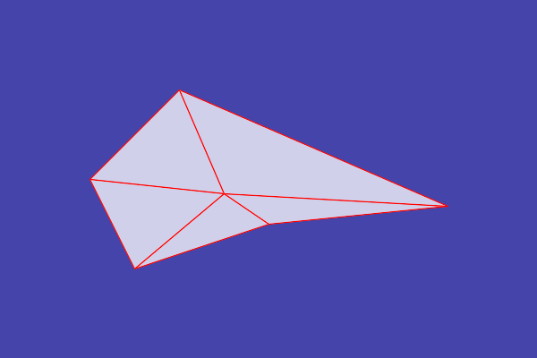
We can format the output to draw triangles:
%IM7DEV%acwise -i acwinp.txt -o acw_3.lis --startat N -fmt triangles
The output file, acw_3.lis, is:
path 'M250,216 L200,100 100,200 z'
path 'M250,216 L100,200 150,300 z'
path 'M250,216 L150,300 300,250 z'
path 'M250,216 L300,250 500,230 z'
path 'M250,216 L500,230 200,100 z'
%IMG7%magick ^ -size 600x400 xc:#44a ^ -fill sRGBA(100%%,100%%,100%%,0.75) -stroke Red ^ -draw @acw_3.lis ^ acw_3.png |

|
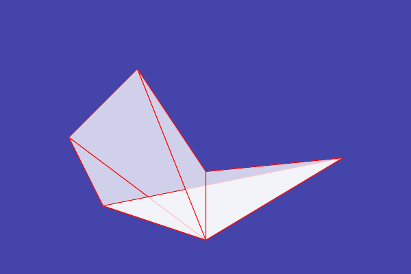
We might choose a centre that is outside the bounding box of the points. In this example, this changes the order of the points in a polygon.
%IM7DEV%acwise -i acwinp.txt -o acw_4.lis --startat N -fmt triangles --centre 300,350
The output file, acw_4.lis, is:
path 'M300,350 L200,100 100,200 z'
path 'M300,350 L100,200 150,300 z'
path 'M300,350 L150,300 500,230 z'
path 'M300,350 L500,230 300,250 z'
path 'M300,350 L300,250 200,100 z'
%IMG7%magick ^ -size 600x400 xc:#44a ^ -fill sRGBA(100%%,100%%,100%%,0.75) -stroke Red ^ -draw @acw_4.lis ^ acw_4.png |
|
Perhaps we list the points in the order we want them, and the program "sorts" them out of this order. The option --nosort is useful for this.
( echo 50,50
  echo 310,300
  echo 550,70
  echo 290,350
) >acw_u-shape.txt
%IM7DEV%acwise ^
  -i acw_u-shape.txt -o acw_u-shape.lis ^
  -fmt curve

%IMG7%magick ^
  -size 600x400 xc:#44a ^
  -fill sRGBA(100%%,100%%,100%%,0.75) ^
  -stroke Red ^
  -draw @acw_u-shape.lis ^
  acw_u-shape.png
This is not the curve I wanted. |

|
|
Include "--nosort" to prevent sorting. %IM7DEV%acwise ^ -i acw_u-shape.txt -o acw_u-shape2.lis ^ --nosort ^ -fmt curve %IMG7%magick ^ -size 600x400 xc:#44a ^ -fill sRGBA(100%%,100%%,100%%,0.75) ^ -stroke Red ^ -draw @acw_u-shape2.lis ^ acw_u-shape2.png Yes, that's what I wanted. |

|
The program can arrange the data for IM paths in various formats.
|
Polygon %IM7DEV%acwise ^ -i acwinp.txt -o acw_polygon.lis ^ --startat N -fmt polygon %IMG7%magick ^ -size 600x400 xc:#44a ^ -fill sRGBA(100%%,100%%,100%%,0.75) ^ -stroke Red ^ -draw @acw_polygon.lis ^ acw_polygon.png |

|
|
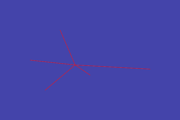
Spokes %IM7DEV%acwise ^ -i acwinp.txt -o acw_spokes.lis ^ --startat N -fmt spokes %IMG7%magick ^ -size 600x400 xc:#44a ^ -fill sRGBA(100%%,100%%,100%%,0.75) ^ -stroke Red ^ -draw @acw_spokes.lis ^ acw_spokes.png |
|
|
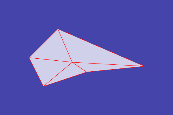
Triangles %IM7DEV%acwise ^ -i acwinp.txt -o acw_triangles.lis ^ --startat N -fmt triangles %IMG7%magick ^ -size 600x400 xc:#44a ^ -fill sRGBA(100%%,100%%,100%%,0.75) ^ -stroke Red ^ -draw @acw_triangles.lis ^ acw_triangles.png |
|
|
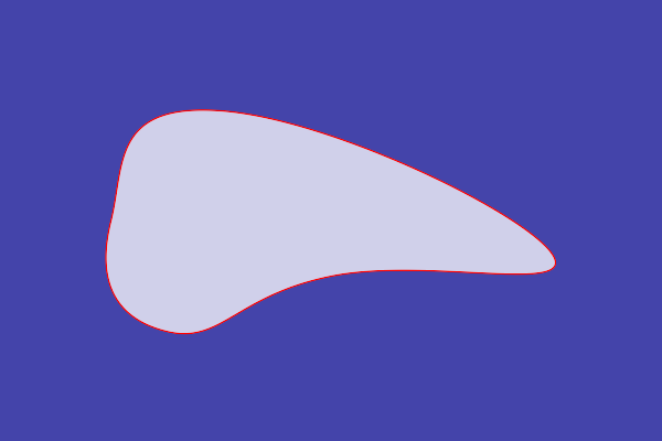
Curve %IM7DEV%acwise ^ -i acwinp.txt -o acw_curve.lis ^ --startat N -fmt curve %IMG7%magick ^ -size 600x400 xc:#44a ^ -fill sRGBA(100%%,100%%,100%%,0.75) ^ -stroke Red ^ -draw @acw_curve.lis ^ acw_curve.png |
|
|
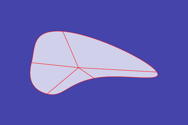
Wheel %IM7DEV%acwise ^ -i acwinp.txt -o acw_wheel.lis ^ --startat N -fmt wheel %IMG7%magick ^ -size 600x400 xc:#44a ^ -fill sRGBA(100%%,100%%,100%%,0.75) ^ -stroke Red ^ -draw @acw_wheel.lis ^ acw_wheel.png |
|
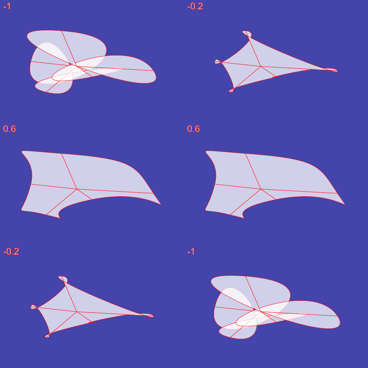
The formats curve and wheel work with control points that determine the tangent direction and length at each point. Currently, the direction will be parallel to a line between the adjacent points, and the semi-tangent length will be 0.25 times the length of that line. (Future enhancements may allow further options.)
Tightness values between 0.0 and 0.5 are good. Values outside this range will often often make the curve loop back on itself. A value of 0.0 gives the same result as the polygon format
We can illustrate the effect with an animation:goto skiptt
del %TEMP%\acw_*.png 2>nul
for /L %%N in (0,1,100) do (
for /F "usebackq" %%F in (`%IMG7%magick xc: -format "TT=%%[fx:%%N*2/100-1]" info:`) do set %%F
%IM7DEV%acwise -i acwinp.txt -o acw_anim.lis --startat N -fmt wheel --tantight !TT!
set LZ=000000%%N
set LZ=!LZ:~-6!
echo LZ=!LZ!
%IMG7%magick ^
-size 600x400 xc:#44a ^
-fill "sRGBA(100%%,100%%,100%%,0.75)" -stroke Red ^
-draw @acw_anim.lis ^
-pointsize 30 ^
-annotate +10+30 !TT! ^
%TEMP%\acw_!LZ!.png
)
%IMG7%magick ^
  %TEMP%\acw_*.png ^
  ( -clone 0--1 ^
    -reverse ^
  ) ^
  -layers optimize ^
  acw_anim.gif

:skiptt
|
|
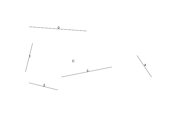
The --explain option is useful for understanding the workings, or debugging. It needs a file prefix that will be used as the name of a partial IM script that can be used to create a PNG file with the same prefix. That image shows the order of the points, and the tangents.
%IM7DEV%acwise ^
  -i acwinp.txt -o acw_wheel_exp.lis ^
  --startat N -fmt wheel --explain acw_exp
This has created a file named acw_exp_explain.lis:
-annotate +200+100 0
-annotate +100+200 1
-annotate +150+300 2
-annotate +300+250 3
-annotate +500+230 4
-annotate +250+216 C
-draw "path 'M200,100 L100,92.5'"
-draw "path 'M100,200 L112.5,150'"
-draw "path 'M100,200 L87.5,250'"
-draw "path 'M150,300 L100,287.5'"
-draw "path 'M150,300 L200,312.5'"
-draw "path 'M300,250 L212.5,267.5'"
-draw "path 'M300,250 L387.5,232.5'"
-draw "path 'M500,230 L525,267.5'"
-draw "path 'M500,230 L475,192.5'"
-draw "path 'M200,100 L300,107.5'"
-write acw_exp_explain.png
NULL:
We can use this to create an explanatory image with a transparent background so it can be composited over the main image.
%IMG7%magick ^ -size 600x400 xc:None ^ -script acw_exp_explain.lis |
|
%IMG7%magick ^
  -size 600x400 xc:#44a ^
  -fill sRGBA(100%%,100%%,100%%,0.75) ^
  -stroke Red ^
  -draw @acw_wheel_exp.lis ^
  acw_exp_explain.png ^
  -composite ^
  acw_wheelexp.png
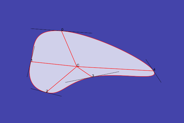
The points are numbered, and we can see these are in anti-clockwise order, and the most northerly point is listed first.
As a second example, we use the same points, but we reverse the order.
%IM7DEV%acwise ^
  -i acwinp.txt -o acw_wheel_exp2.lis ^
  --reverse ^
  --startat N -fmt wheel --explain acw_exp2
Create an explanatory image, and composite that over the curve image:
%IMG7%magick ^
  -size 600x400 xc:None ^
  -script acw_exp2_explain.lis

%IMG7%magick ^
  -size 600x400 xc:#44a ^
  -fill sRGBA(100%%,100%%,100%%,0.75) ^
  -stroke Red ^
  -draw @acw_wheel_exp2.lis ^
  acw_exp2_explain.png ^
  -composite ^
  acw_wheelexp2.png
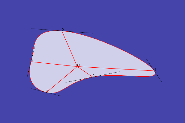
The numbering of the points shows they are in clockwise order.
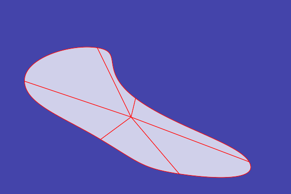
For the input to acwise, we can generate a random number of random coordinates. Suppose we want N points. We create a Nx1 image, then use -fx so assign random values to the red and green channels. Then we write those channels to ftxt: format.
%IMG7%magick ^
  -size %%[fx:floor(rand()*4+3)]x1 xc: ^
  -channel R -fx "floor (rand() * 600)" ^
  -channel G -fx "floor (rand() * 400)" ^
  -channel RG ^
  -define ftxt:format=\o\n ^
  ftxt:acw_rand.lis
0 <= rand() < 1, so the number of points will be between 3 and 6 pixels, inclusive. The generated coordinates will be 0 <= x < 600 and 0 <= y < 400.
This has created acw_rand.lis:
279,202
200,98
513,333
369,358
207,287
50,167
We create an image from those points. We pipe the text output from acwise into the -draw input of magick, so there is no need to write an intermediate file to disk.
%IM7DEV%acwise ^ -i acw_rand.lis ^ -o - ^ -fmt wheel | %IMG7%magick ^ -size 600x400 xc:#44a ^ -fill sRGBA(100%%,100%%,100%%,0.75) ^ -stroke Red ^ -draw @- ^ acw_rand.png |
|
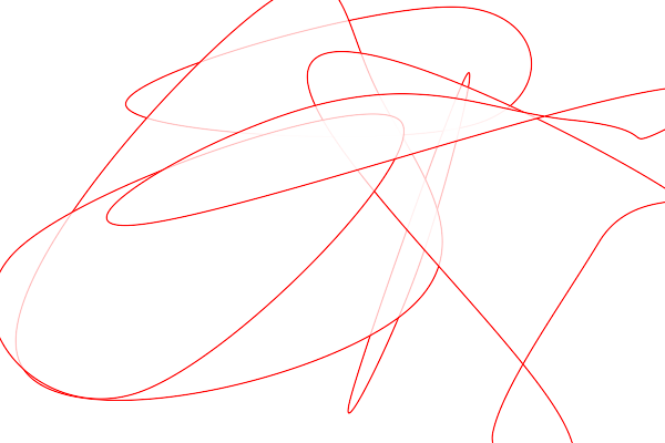
We can do this multiple times. This also pipes the random coordinates created by the first magick into acwise.
%IMG7%magick ^ -size 600x400 xc:None ^ acw_rand_mult.png for /L %%N in (0,1,5) do %IMG7%magick ^ -size %%[fx:floor(rand()*4+3)]x1 xc: ^ -channel R -fx "floor (rand() * 600)" ^ -channel G -fx "floor (rand() * 400)" ^ -channel RG ^ -define ftxt:format=\o\n ^ ftxt:- | %IM7DEV%acwise ^ -i - ^ -o - ^ -fmt curve | %IMG7%magick ^ -size 600x400 xc:None ^ -fill sRGBA(100%%,100%%,100%%,0.75) ^ -stroke Red ^ -draw @- ^ acw_rand_mult.png ^ -compose DstOver -composite ^ acw_rand_mult.png |
|
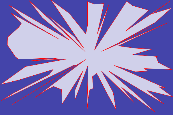
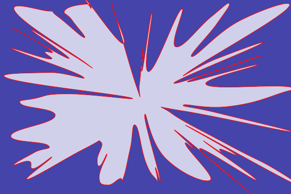
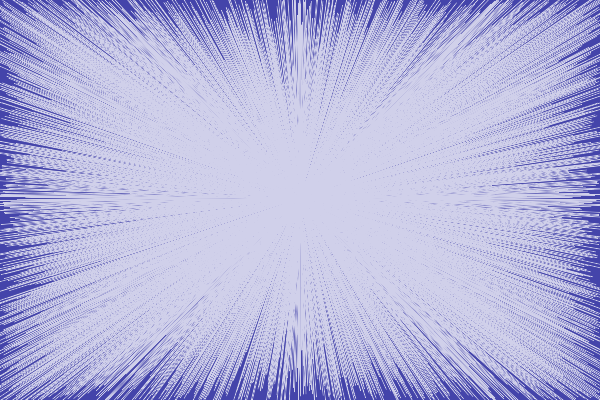
We can go crazy with the number of points:
%IMG7%magick ^ -size 100x1 xc: ^ -channel R -fx "floor (rand() * 600)" ^ -channel G -fx "floor (rand() * 400)" ^ -channel RG ^ -define ftxt:format=\o\n ^ ftxt:- | %IM7DEV%acwise ^ -i - ^ -o - ^ -fmt polygon | %IMG7%magick ^ -size 600x400 xc:#44a ^ -fill sRGBA(100%%,100%%,100%%,0.75) ^ -stroke Red ^ -draw @- ^ acw_rand_crazy.png |
|
%IMG7%magick ^ -size 100x1 xc: ^ -channel R -fx "floor (rand() * 600)" ^ -channel G -fx "floor (rand() * 400)" ^ -channel RG ^ -define ftxt:format=\o\n ^ ftxt:- | %IM7DEV%acwise ^ -i - ^ -o - ^ -fmt curve | %IMG7%magick ^ -size 600x400 xc:#44a ^ -fill sRGBA(100%%,100%%,100%%,0.75) ^ -stroke Red ^ -draw @- ^ acw_rand_crazy2.png |
|
%IMG7%magick ^ -size 10000x1 xc: ^ -channel R -fx "floor (rand() * 600)" ^ -channel G -fx "floor (rand() * 400)" ^ -channel RG ^ -define ftxt:format=\o\n ^ ftxt:- | %IM7DEV%acwise ^ -i - ^ -o - ^ -fmt curve | %IMG7%magick ^ -size 600x400 xc:#44a ^ -fill sRGBA(100%%,100%%,100%%,0.75) ^ -stroke None ^ -draw @- ^ acw_rand_crazy3.png |
|
We can choose colours for the individual paths listed in acwise's output by processing the text. Just for fun, we also make the strokes wider, with round ends.
set TMP_PATHS0=%TEMP%\acw_tmp0.lis
set TMP_PATHS1=%TEMP%\acw_tmp.lis

del %TMP_PATHS0% 2>nul
del %TMP_PATHS1% 2>nul

%IM7DEV%acwise ^
  -i acwinp.txt -o %TMP_PATHS0% ^
  --startat N -fmt triangles

set nCols=3

set n=0
for /F "tokens=*" %%L in (%TMP_PATHS0%) do (
  for /F "tokens=1" %%A in ("%%L") do (
    if "%%A"=="path" (
      set /A ColNum=n%%%nCols%
      if !ColNum!==0 set sCol=#f88
      if !ColNum!==1 set sCol=#0b0
      if !ColNum!==2 set sCol=#00f
      echo fill !sCol! stroke-linecap round stroke-linejoin round >>%TMP_PATHS1%
      set /A n+=1
    )
    echo %%L >>%TMP_PATHS1%
  )
)

%IMG7%magick ^
  -size 600x400 xc:#44a ^
  -fill sRGBA(100%%,100%%,100%%,0.75) ^
  -stroke Red -strokewidth 5 ^
  -draw @%TMP_PATHS1% ^
  acw_colours.png
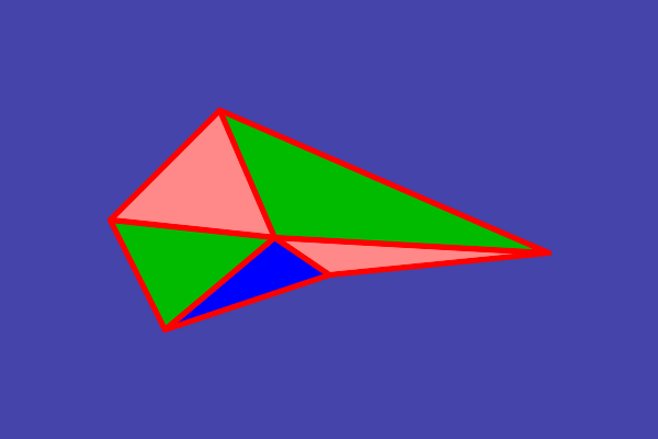
Examples above have created paths that can be included in an IM -draw command. Instead, we can create paths that can be included in an SVG file.
%IM7DEV%acwise -i acwinp.txt -o acw_svg.lis --startat N -svg -fmt triangles
The output file, acw_svg.lis, is:
<path d="M250,216 L200,100 100,200 z"/>
<path d="M250,216 L100,200 150,300 z"/>
<path d="M250,216 L150,300 300,250 z"/>
<path d="M250,216 L300,250 500,230 z"/>
<path d="M250,216 L500,230 200,100 z"/>
We can make this into a complete SVG file by adding some prefix and suffix text. The text file acwise_svg_pref.txt is:
<?xml version="1.0" ?>
<!DOCTYPE svg  PUBLIC '-//W3C//DTD SVG 1.1//EN'  'http://www.w3.org/Graphics/SVG/1.1/DTD/svg11.dtd'>
<svg enable-background="new 0 0 600 400" id="Layer_1" version="1.1" viewBox="0 0 600 400"
xml:space="preserve"
xmlns="http://www.w3.org/2000/svg"
xmlns:xlink="http://www.w3.org/1999/xlink">
<g fill="#44f" stroke="#f22">
This prefix file contains the required dimensions (600x400 pixels), and default colours for the paths.
The text file acwise_svg_suff.txt is simpler:
</g></svg>
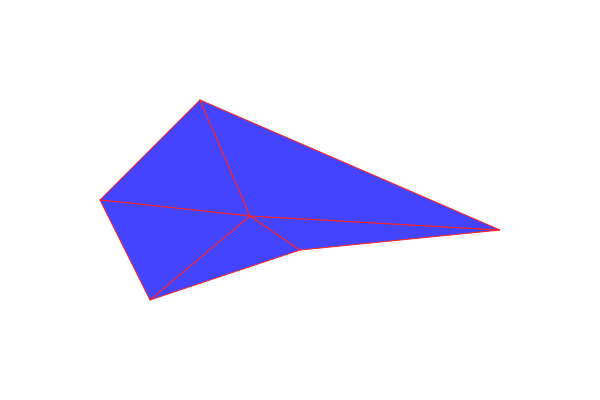
We append the three text files to make a complete SVG file, then use magick to rasterize it.
copy /Y /B ^ acwise_svg_pref.txt+acw_svg.lis+acwise_svg_suff.txt ^ acw_svg.svg %IMG7%magick ^ -background None ^ acw_svg.svg ^ acw_svg.png |
|
|
We can deliver the SVG to the web browser, with a fallback PNG version: |
gradient morphology. Finds the point that is furthest from any edge.
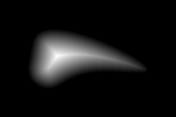
We make an image that has a white shape on a black background, and do a "-morphology Distance" operation.
%IMG7%magick ^
  -size 600x400 xc:Black ^
  -fill White -stroke None ^
  -draw @acw_curve.lis ^
  -morphology Distance Euclidean:7,100 ^
  -alpha off ^
  -auto-level ^
  +write acw_morph_grad.png ^
  -define identify:locate=maximum ^
  info:
Channel maximum locations: Red: 65535 (1) 195,191 Green: 65535 (1) 195,191 Blue: 65535 (1) 195,191 |
|
The lightest pixel in the result is the furthest from any edge of the shape. This will usually not be the same as the centroid of the points or the centroid of the shape.
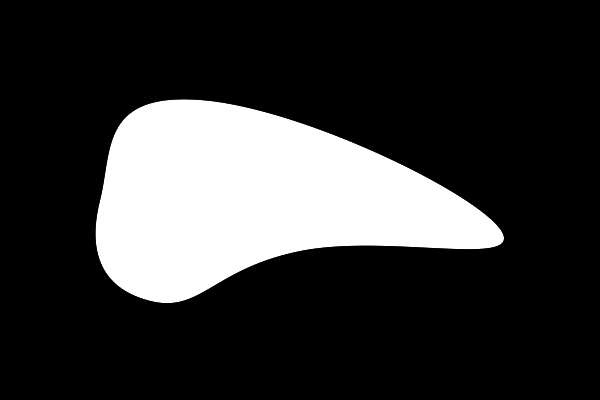
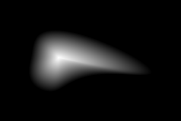
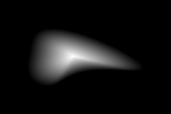
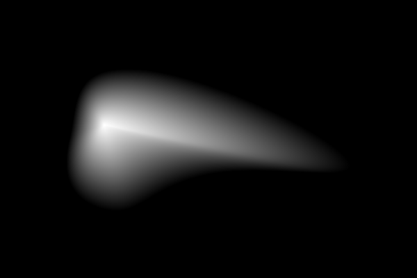
With more effort, we can make a gradient centred at any location within the shape, provided the edge is entirely visible from that location. We do this by unrolling the shape, making a gradient black at the top to white at the bottom, dividing each column of the gradient by the fraction of the unrolled image that is white, then rolling up the result. That work is done in the script shp2grad.bat (see Gradients). The script also sets environment variables shp2gCX and shp2gCY.
%IMG7%magick ^ -size 600x400 xc:Black ^ -fill White -stroke None ^ -draw @acw_curve.lis ^ acw_wonb.png |
|
|
Use the furthest point from the shape edge. call %PICTBAT%shp2grad ^ acw_wonb.png ^ acw_wonb_grad.png ^ . -negate echo shp2gCX=%shp2gCX% shp2gCY=%shp2gCY% shp2gCX=195 shp2gCY=191 |
|
|
Use centroid of the shape. call %PICTBAT%shp2grad ^ acw_wonb.png ^ acw_wonb_grad_cent.png ^ centroid -negate echo shp2gCX=%shp2gCX% shp2gCY=%shp2gCY% shp2gCX=255.3 shp2gCY=198.0 |
|
|
Use centre at 25% of width and 45% of height. call %PICTBAT%shp2grad ^ acw_wonb.png ^ acw_wonb_grad_dims.png ^ 25cx45c -negate echo shp2gCX=%shp2gCX% shp2gCY=%shp2gCY% shp2gCX=150 shp2gCY=180 |
|
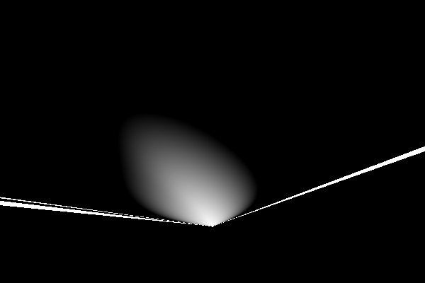
If we use a centre that is outside the shape:
|
Use centre at 50% of width and 80% of height. call %PICTBAT%shp2grad ^ acw_wonb.png ^ acw_wonb_grad_dims2.png ^ 50cx80c -negate echo shp2gCX=%shp2gCX% shp2gCY=%shp2gCY% shp2gCX=300 shp2gCY=320 |
|
We also need a radial gradient, which is trivial: the angle around the centre. (It might be neat if we could distort that gradient so 1° of change sweeps an equal area, regardless of polar distance; hence the actual angle would be inversely proportional to the polar distance.)
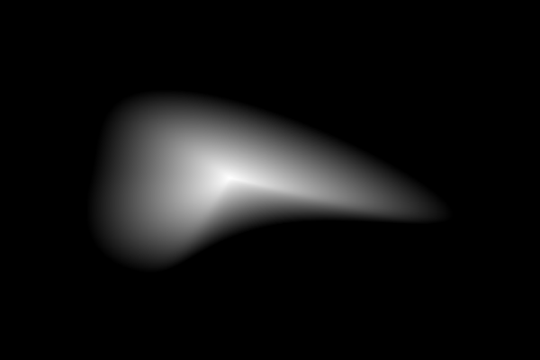
We use the two gradients in a polar displacement map, recording rho and theta. For rho, we want black in the shape's centre and white at the edges.
|
Use centre at centroid. call %PICTBAT%shp2grad ^ acw_wonb.png ^ acw_map_r.png ^ centroid -negate echo shp2gCX=%shp2gCX% shp2gCY=%shp2gCY% shp2gCX=255.3 shp2gCY=198.0 |
|
|
Make a circular gradient. call %PICTBAT%circGrad ^ 600x400 acw_map_g.png %shp2gCX%x%shp2gCY% |

|
|
Combine the images to make a map. %IMG7%magick ^
( acw_map_r.png -negate )^
acw_map_g.png ^
( +clone ^
-fill Black -colorize 100 ^
) ^
-combine ^
acw_map_rgb.png
|
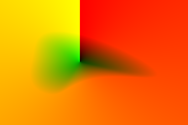
|
When applying the map, these give the look-up into an image, eg with "-fx "MX=...; MY=...; p{MX,MY}"". If that image is a circle or ellipse, the look-up is trivial.
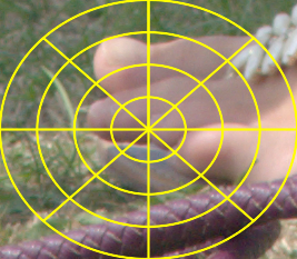
We demonstrate this with an image that has an elliptical grid to show what is happening. It doesn't need to be the same size or aspect ratio as the map.
call %PICTBAT%ellipseGridOver ^ toes.png ^ toes_egrd.png |
|
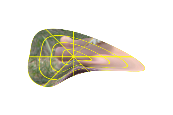
Now we can apply the rhoTheta map.
set sFX=^
  ANG = v.g*2*pi; ^
  VW = %%[fx:(v.w-1)/2]; ^
  VH = %%[fx:(v.h-1)/2]; ^
  MX = v.r*VW*sin(ANG); ^
  MY = v.r*VH*cos(ANG); ^
  p{MX+VW,v.h-MY-VH}

%IMG7%magick ^
  ( toes_egrd.png -resize "600x400^!" ) ^
  acw_map_rgb.png ^
  -fx "%sFX%" ^
  acw_wonb.png ^
  -alpha off -compose CopyOpacity -composite ^
  acw_mapped.png
|
|
See also Direct polar distortion: Identity map.
For convenience, .bat scripts are also available in a single zip file. See Zipped BAT files.
#include <stdio.h>
#include <string.h>
#include <stdlib.h>
#include <math.h>

/*
  This program is copyright (c) 2023 Alan Gibson ("snibgo").

  Anyone is permitted to use or adapt any of the code for any purpose, including commercial use.

  Build:
    bash snibgo\buildc.sh snibgo\acwise
*/

typedef int BOOL;
#define TRUE 1
#define FALSE 0

typedef struct {
  double x, y;
  double dx, dy;
} CoordT;

/* The directions assume origin is at top-left,
   so "N" is the coord with lowest y coordinate, etc.
*/
typedef enum {
  dN, dNE, dE, dSE, dS, dSW, dW, dNW, dUndef
} DirectionT;

typedef struct {
  DirectionT dirn;
  const char * strDirn;
} strDirectionT;

strDirectionT strDirections[] = {
  {dN,  "N"},
  {dNE, "NE"},
  {dE,  "E"},
  {dSE, "SE"},
  {dS,  "S"},
  {dSW, "SW"},
  {dW,  "W"},
  {dNW, "NW"},
  {dUndef, "undefined"}
};

typedef enum {
  ofCoords, ofPolygon, ofSpokes, ofTriangles, ofCurve, ofWheel, ofUndef
} OutFmtT;

typedef struct {
  OutFmtT outFmt;
  const char * strOutFmt;
} strOutFmtT;

strOutFmtT strOutFmts[] = {
  {ofCoords,    "coords"},
  {ofPolygon,   "polygon"},
  {ofSpokes,     "spokes"},
  {ofTriangles, "triangles"},
  {ofCurve,     "curve"},
  {ofWheel,     "wheel"},
  {ofUndef,     "undefined"}
};

/* TODO: curved polygons.
*/

typedef struct {
  BOOL do_verbose, do_help;
  BOOL do_sort, do_reverse, do_centroid;
  BOOL JoinPaths;
  BOOL SVGformat;
  FILE * fh_data;
  FILE * fh_explain;
  char * infile;
  char * outfile;
  char * explainPrefix;
  OutFmtT OutFmt;
  CoordT Centre;
  DirectionT dirn;
  double TanTight;
  size_t MaxCoords;
  size_t NumCoords;
  CoordT * Coords;
  size_t StartAt;
  char * PathPrefix;
  char * PathSuffix;
} acwiseT;

#define IM_PREFIX "path \'"
#define IM_SUFFIX "\'"
#define SVG_PREFIX "<path d=\""
#define SVG_SUFFIX "\"/>"


static DirectionT DirnOfStr (const char * s)
{
  size_t NumDirns = sizeof (strDirections) / sizeof (strDirectionT);

  size_t i;
  for (i=0; i < NumDirns; i++) {
    if (strcasecmp (s, strDirections[i].strDirn) == 0) break;
  }

  if (i < NumDirns) return strDirections[i].dirn;
  return dUndef;
}

static OutFmtT OutFmtOfStr (const char * s)
{
  size_t NumOutFmts = sizeof (strOutFmts) / sizeof (strOutFmtT);

  size_t i;
  for (i=0; i < NumOutFmts; i++) {
    if (strcasecmp (s, strOutFmts[i].strOutFmt) == 0) break;
  }

  if (i < NumOutFmts) return strOutFmts[i].outFmt;
  return ofUndef;
}

static void usage (void)
{
  size_t NumStrs;
  size_t i;

  printf ("Usage: acwise [OPTION]...'\n");
  printf ("\n");
  printf ("  -i,   --infile string     input text file, or - for stdin\n");
  printf ("  -o,   --outfile string    output text file, or - for stdout\n");
  printf ("  -x,   --explain string    prefix for explanation text file, or - for stdout\n");
  printf ("  -n,   --nosort            don't sort\n");
  printf ("  -r,   --reverse           reverse the order\n");
  printf ("  -c,   --centre X,Y        calculate from given centre (floating-point numbers)\n");
  printf ("  -s,   --startat string    start at direction; one of:");
  NumStrs = sizeof (strDirections) / sizeof (strDirectionT);
  for (i=0; i < NumStrs-1; i++) {
    printf (" %s", strDirections[i].strDirn);
  }
  printf ("\n");

  printf ("  -t,   --tantight number   tightness of tangent for curve and wheel (typically 0.0 to about 0.5)\n");

  printf ("  -fmt, --format string     output format; one of:");
  NumStrs = sizeof (strOutFmts) / sizeof (strOutFmtT);
  for (i=0; i < NumStrs-1; i++) {
    printf (" %s", strOutFmts[i].strOutFmt);
  }
  printf ("\n");

  printf ("  -j,   --joinpaths         join paths into single path\n");
  printf ("  -svg, --svgformat         SVG format (instead of IM \"-draw path\")\n");
  printf ("  -f,   --file string       write verbose text to stderr or stdout\n");
  printf ("  -v,   --verbose           write text information\n");
  printf ("  -h,   --help              write this usage text\n");
  printf ("\n");

  printf ("If the origin is at top-left, so coordinates increase to the right and down,\n");
  printf ("then the sorted order will be anti-clockwise. Use \"--reverse\" to sort clockwise.\n");
  printf ("\n");
  printf ("If the origin is at bottom-left, so coordinates increase to the right and up,\n");
  printf ("then the sorted order will be clockwise. Use \"--reverse\" to sort anti-clockwise.\n");
  printf ("In addition, the meanings of north and south are inverted.\n");
}
\
/* t relative length of tangents (typically 0.0 to 1.0)
*/


/*===
static int LocaleCompare (const char * s1, const char * s2)
{
  return strcasecmp (s1, s2);
}
===*/

static BOOL IsArg (char * pa, const char * ShtOpt, const char * LongOpt)
{
  if ((strcasecmp(pa, ShtOpt)==0) || (strcasecmp(pa, LongOpt)==0))
    return TRUE;

  return FALSE;
}


static BOOL menu(
  const int argc,
  const char **argv,
  acwiseT * pacw
)
/* Returns MagickTrue if okay. */
{
  BOOL okay = TRUE;
  int i;

  pacw->do_verbose = pacw->do_help = FALSE;
  pacw->do_sort = TRUE;
  pacw->do_reverse = FALSE;
  pacw->do_centroid = TRUE;
  pacw->fh_data = stdout;
  pacw->infile = NULL;
  pacw->outfile = NULL;
  pacw->explainPrefix = NULL;
  pacw->fh_explain = NULL;
  pacw->OutFmt = ofCoords;
  pacw->Centre.x = 0;
  pacw->Centre.y = 0;
  pacw->NumCoords = 0;
  pacw->Coords = NULL;
  pacw->dirn = dUndef;
  pacw->TanTight = 0.25;
  pacw->JoinPaths = FALSE;
  pacw->SVGformat = FALSE;
  pacw->PathPrefix = (char *)IM_PREFIX;
  pacw->PathSuffix = (char *)IM_SUFFIX;

  for (i=1; i < argc; i++) {
    char * pa = (char *)argv[i];

    if (IsArg (pa, "-i", "--infile")) {
      i++;
      if (i < argc) pacw->infile = (char *)argv[i];
      else {
        fprintf (stderr, "acwise: --input needs a filename\n");
        okay = FALSE;
      }
    } else if (IsArg (pa, "-o", "--outfile")) {
      i++;
      if (i < argc) pacw->outfile = (char *)argv[i];
      else {
        fprintf (stderr, "acwise: --outfile needs a string\n");
        okay = FALSE;
      }
    } else if (IsArg (pa, "-x", "--explain")) {
      i++;
      if (i < argc) pacw->explainPrefix = (char *)argv[i];
      else {
        fprintf (stderr, "acwise: --explain needs a string\n");
        okay = FALSE;
      }
    } else if (IsArg (pa, "-n", "--nosort")) {
      pacw->do_sort = FALSE;
    } else if (IsArg (pa, "-r", "--reverse")) {
      pacw->do_reverse = TRUE;
    } else if (IsArg (pa, "-s", "--startat")) {
      i++;
      pacw->dirn = DirnOfStr (argv[i]);
      if (pacw->dirn == dUndef) {
        fprintf (stderr, "acwise: --startat is invalid\n");
        okay = FALSE;
      }
    } else if (IsArg (pa, "-c", "--centre")) {
      i++;
      sscanf (argv[i], "%lg , %lg", &pacw->Centre.x, &pacw->Centre.y);
      pacw->do_centroid = FALSE;
    } else if (IsArg (pa, "-t", "--tantight")) {
      i++;
      sscanf (argv[i], "%lg", &pacw->TanTight);
    } else if (IsArg (pa, "-fmt", "--format")) {
      i++;
      pacw->OutFmt = OutFmtOfStr (argv[i]);
      if (pacw->OutFmt == ofUndef) {
        fprintf (stderr, "acwise: --outfmt is invalid\n");
        okay = FALSE;
      }
    } else if (IsArg (pa, "-j", "--joinpaths")) {
      pacw->JoinPaths = TRUE;
    } else if (IsArg (pa, "-svg", "--svgformat")) {
      pacw->SVGformat = TRUE;
      pacw->PathPrefix = (char *)SVG_PREFIX;
      pacw->PathSuffix = (char *)SVG_SUFFIX;

    } else if (IsArg (pa, "-f", "--file")) {
      i++;
      if (strcasecmp (argv[i], "stdout")==0) pacw->fh_data = stdout;
      else if (strcasecmp (argv[i], "stderr")==0) pacw->fh_data = stderr;
      else okay = FALSE;
    } else if (IsArg (pa, "-h", "--help")) {
      pacw->do_help = TRUE;
    } else if (IsArg (pa, "-v", "--verbose")) {
      pacw->do_verbose = TRUE;
    } else {
      fprintf (stderr, "acwise: ERROR: unknown option XX [%s]\n", pa);
      okay = FALSE;
    }
  }

  if (pacw->do_verbose) {
    fprintf (stderr, "acwise options:");
    if (pacw->infile) fprintf (stderr, "  --infile %s", pacw->infile);
    if (pacw->outfile) fprintf (stderr, "  --outfile %s", pacw->outfile);
    if (pacw->explainPrefix) fprintf (stderr, "  --explain %s", pacw->explainPrefix);
    if (!pacw->do_sort) fprintf (stderr, "  --nosort");
    if (pacw->do_reverse) fprintf (stderr, "  --reverse");
    if (pacw->dirn != dUndef) fprintf (stderr, "  --startat %s", strDirections[pacw->dirn].strDirn);
    if (!pacw->do_centroid) fprintf (stderr, "  --centre %g,%g", pacw->Centre.x, pacw->Centre.y);
    fprintf (stderr, "  --format %s", strOutFmts[pacw->OutFmt].strOutFmt);
    if (pacw->JoinPaths) (stderr, "  --joinpaths");
    if (pacw->SVGformat) (stderr, "  --svgformat");
    if (pacw->OutFmt == ofCurve || pacw->OutFmt == ofWheel) fprintf (stderr, "  --tantight %lg", pacw->TanTight);
    if (pacw->fh_data == stdout) fprintf (stderr, "  --file stdout");
    if (pacw->fh_data == stderr) fprintf (stderr, "  --file stderr");
    if (pacw->do_verbose) fprintf (stderr, "  --verbose");
    if (pacw->do_help) fprintf (stderr, "  --help");
    fprintf (stderr, "\n\n");
  }

  if (!pacw->infile && !pacw->do_help) {
    fprintf (stderr, "Requires --infile\n");
    okay = FALSE;
  }

  if (!okay || pacw->do_help)
    usage ();

  return okay;
}


#define TableExtend 0.1
#define InitMaxCoords 50

static BOOL InitAcw (acwiseT * pacw)
{
  pacw->MaxCoords = InitMaxCoords;
  pacw->NumCoords = 0;
  pacw->Coords = (CoordT *) malloc (pacw->MaxCoords * sizeof(CoordT));
  if (!pacw->Coords) {
    fprintf (stderr, "InitAcw oom");
    return FALSE;
  }
  pacw->StartAt = 0;

  return TRUE;
}

static BOOL DeInitAcw (acwiseT * pacw)
{
  pacw->NumCoords = 0;
  pacw->MaxCoords = 0;
  if (pacw->Coords) {
    free (pacw->Coords);
    pacw->Coords = NULL;
  }

  return TRUE;
}

static BOOL ExtendCoords (acwiseT * pacw)
{
  pacw->MaxCoords = (size_t)(ceil ((double)pacw->MaxCoords * (1.0 + TableExtend)));
  pacw->Coords = (CoordT *) realloc (pacw->Coords, pacw->MaxCoords * sizeof(CoordT));
  if (!pacw->Coords) {
    fprintf (stderr, "ExtendCoords oom");
    return FALSE;
  }

  return TRUE;
}


static BOOL AddCoords (acwiseT * pacw, double x, double y)
{
  if (pacw->NumCoords == pacw->MaxCoords) {
    if (!ExtendCoords (pacw)) return FALSE;
  }

  {
    CoordT * pc = &pacw->Coords[pacw->NumCoords];
    pc->x = x;
    pc->y = y;
    pacw->NumCoords++;
  }

  return TRUE;
}


static BOOL ReadCoords (acwiseT * pacw)
{
  FILE * fh;
  double x, y;
  int n;

  if (strcmp (pacw->infile, "-") == 0) {
    fh = stdin;
  } else {
    fh = fopen (pacw->infile, "rt");
    if (!fh) {
      fprintf (stderr, "Failed to open %s\n", pacw->infile);
      return FALSE;
    }
  }

  n = fscanf (fh, "%lg , %lg", &x, &y);

  while (n != EOF) {
    AddCoords (pacw, x, y);
    n = fscanf (fh, "%lg , %lg", &x, &y);
  }

  if (strcmp (pacw->infile, "-") != 0) {
    fclose (fh);
  }

  if (pacw->do_verbose) {
    fprintf (pacw->fh_data, "NumCoords = %lu\n", pacw->NumCoords);
  }
  return TRUE;
}


static void CalcCentroid (acwiseT * pacw)
{
  size_t i;
  double cx=0, cy=0;
  for (i=0; i < pacw->NumCoords; i++) {
    CoordT * pc = &pacw->Coords[i];
    cx += pc->x;
    cy += pc->y;
  }
  cx /= (double)pacw->NumCoords;
  cy /= (double)pacw->NumCoords;
  if (pacw->do_verbose) {
    fprintf (pacw->fh_data, "Centroid = %g,%g\n", cx, cy);
  }
  pacw->Centre.x = cx;
  pacw->Centre.y = cy;
}

static void CalcDiffs (acwiseT * pacw)
{
  size_t i;
  for (i=0; i < pacw->NumCoords; i++) {
    CoordT * pc = &pacw->Coords[i];
    pc->dx = pc->x - pacw->Centre.x;
    pc->dy = pc->y - pacw->Centre.y;
  }
}

static int CompareCoords (const void *a, const void *b)
{
  CoordT * pcA = (CoordT *) a;
  CoordT * pcB = (CoordT *) b;
  /* Determinant is the signed area of the parallogram of the two vectors: centre to a, and centre to b.
  */
  double det = pcA->dx * pcB->dy - pcB->dx * pcA->dy;
  if (det < 0) return -1;
  if (det > 0) return +1;

  /* They are on the same radius.
  */
  {
    double d1 = pcA->dx * pcA->dx + pcA->dy * pcA->dy;
    double d2 = pcB->dx * pcB->dx + pcB->dy * pcB->dy;
    if (d1 > d2) return -1;
    if (d1 < d2) return +1;
  }
  return 0;
}

static int CompareCoordsReverse (const void *a, const void *b)
{
  return CompareCoords (b, a);
}

static void SortCoords (acwiseT * pacw)
{
  /* When (0,0) is top-left, this gives anticlockwise.
  */
  if (pacw->NumCoords <= 1) return;

  if (pacw->do_reverse) {
    qsort ((void *)pacw->Coords, pacw->NumCoords, sizeof (CoordT), CompareCoordsReverse);
  } else {
    qsort ((void *)pacw->Coords, pacw->NumCoords, sizeof (CoordT), CompareCoords);
  }
}

static void FindStartAt (acwiseT * pacw)
{
  size_t limNdx = 0;
  double val, limVal = 0;
  BOOL better;
  size_t i;

  if (pacw->dirn == dUndef) return;

  for (i=0; i < pacw->NumCoords; i++) {
    const CoordT * pc = &pacw->Coords[i];
    val = pc->y;
    better = val < limVal;
    switch (pacw->dirn) {
      case dN:
        val = pc->y;
        better = val < limVal;
        break;
      case dNE:
        val = pc->x - pc->y;
        better = val > limVal;
        break;
      case dE:
        val = pc->x;
        better = val > limVal;
        break;
      case dSE:
        val = pc->x + pc->y;
        better = val > limVal;
        break;
      case dS:
        val = pc->y;
        better = val > limVal;
        break;
      case dSW:
        val = pc->x - pc->y;
        better = val < limVal;
        break;
      case dW:
        val = pc->x;
        better = val < limVal;
        break;
      case dNW:
        val = pc->x + pc->y;
        better = val < limVal;
        break;
      case dUndef:
        val = 0;
        better = FALSE;
        break;
    }
    if (i==0 || better) {
      limVal = val;
      limNdx = i;
    }
  }
  pacw->StartAt = limNdx;
}

#define NL_EVERY 50

static void WrCoords (const acwiseT * pacw, FILE * fh)
{
  size_t i;
  for (i=0; i < pacw->NumCoords; i++) {
    const CoordT * pc = &pacw->Coords[(i + pacw->StartAt) % pacw->NumCoords];
    fprintf (fh, "%g,%g\n", pc->x, pc->y);
  }
}


static void WrPolyPath (const acwiseT * pacw, FILE * fh)
/* Write data as a polygon path.
*/
{
  size_t i;
  CoordT * pc;

  if (pacw->NumCoords < 2) return;

  pc = &pacw->Coords[pacw->StartAt];
  fprintf (fh, "%s M%g,%g L", pacw->PathPrefix, pc->x, pc->y);

  for (i=1; i < pacw->NumCoords; i++) {
    const CoordT * pc = &pacw->Coords[(i + pacw->StartAt) % pacw->NumCoords];
    fprintf (fh, "%g,%g ", pc->x, pc->y);
    if ((i+1) % NL_EVERY == 0) fprintf (fh, "\n");
  }
  fprintf (fh, "z%s\n", pacw->PathSuffix);
}

static void WrSpokesPath (const acwiseT * pacw, FILE * fh)
/* Write data as a Spokes path.
*/
{
  size_t i;

  if (pacw->NumCoords < 2) return;

  fprintf (fh, "%s", pacw->PathPrefix);

  for (i=0; i < pacw->NumCoords; i++) {
    const CoordT * pc = &pacw->Coords[(i + pacw->StartAt) % pacw->NumCoords];
    fprintf (fh, "M%g,%g L%g,%g\n", pacw->Centre.x, pacw->Centre.y, pc->x, pc->y);
    if ((i+1) % NL_EVERY == 0) fprintf (fh, "\n");
  }
  fprintf (fh, "z%s\n", pacw->PathSuffix);
}

static void WrTrianglesPath (const acwiseT * pacw, FILE * fh)
/* Write data as triangles path.
*/
{
  size_t i;

  if (pacw->NumCoords < 2) return;

  if (pacw->JoinPaths) fprintf (fh, "%s", pacw->PathPrefix);

  for (i=0; i < pacw->NumCoords; i++) {
    const CoordT * pc = &pacw->Coords[(i + pacw->StartAt) % pacw->NumCoords];
    const CoordT * pcNext = &pacw->Coords[(i + pacw->StartAt + 1) % pacw->NumCoords];
    if (!pacw->JoinPaths) fprintf (fh, "%s", pacw->PathPrefix);
    fprintf (fh, "M%g,%g L%g,%g %g,%g z", pacw->Centre.x, pacw->Centre.y, pc->x, pc->y, pcNext->x, pcNext->y);
    if (!pacw->JoinPaths) fprintf (fh, "%s", pacw->PathSuffix);
    fprintf (fh, "\n");
  }
  if (pacw->JoinPaths) fprintf (fh, "%s\n", pacw->PathSuffix);
}

static void WrCurvePath (const acwiseT * pacw, FILE * fh)
/* Write data as one closed curved path. (Cubic Bezier.)
*/
{
  size_t i;
  CoordT * pc;

  if (pacw->NumCoords < 3) return;

  pc = &pacw->Coords[pacw->StartAt];
  fprintf (fh, "%s M%g,%g\n", pacw->PathPrefix, pc->x, pc->y);

  /* This sets the tangent at each point parallel to the line between the adjacent points,
     and each semi-tangent is a fraction of the length of that line.

     An alternative would be to make the tangent perpendicular to the line to the centre,
     and the length could be proprtional to that.

     In each iteration, create the curve between nM1 and n0.

     Possible enhancement: limit tangent lengths so they don't cross.
  */

  for (i=1; i <= pacw->NumCoords; i++) {
    size_t nM2 = (i + pacw->StartAt - 2 + pacw->NumCoords) % pacw->NumCoords;
    size_t nM1 = (nM2 +1) % pacw->NumCoords;
    size_t n0  = (nM1 +1) % pacw->NumCoords;
    size_t nP1 = (n0  +1) % pacw->NumCoords;
    const CoordT * pcM2 = &pacw->Coords[nM2];
    const CoordT * pcM1 = &pacw->Coords[nM1];
    const CoordT * pc = &pacw->Coords[n0];
    const CoordT * pcP1 = &pacw->Coords[nP1];
    const double dx0 = (pcM2->x - pc->x)   * pacw->TanTight;
    const double dy0 = (pcM2->y - pc->y)   * pacw->TanTight;
    const double dx1 = (pcP1->x - pcM1->x) * pacw->TanTight;
    const double dy1 = (pcP1->y - pcM1->y) * pacw->TanTight;
    CoordT cp1, cp2;
    cp1.x = pcM1->x - dx0;
    cp1.y = pcM1->y - dy0;
    cp2.x = pc->x - dx1;
    cp2.y = pc->y - dy1;
    fprintf (fh, "C%g,%g %g,%g %g,%g\n", cp1.x, cp1.y, cp2.x, cp2.y, pc->x, pc->y);
    if (pacw->fh_explain) {
      fprintf (pacw->fh_explain, "-draw \"path 'M%g,%g L%g,%g'\"\n", pcM1->x, pcM1->y, cp1.x, cp1.y);
      fprintf (pacw->fh_explain, "-draw \"path 'M%g,%g L%g,%g'\"\n", pc->x, pc->y, cp2.x, cp2.y);
    }
  }
  fprintf (fh, "z%s\n", pacw->PathSuffix);
}

static void WrWheelPath (const acwiseT * pacw, FILE * fh)
/* A curve with spokes. Each set of two spokes and adjoining curve is a closed path.
*/
{
  size_t i;

  if (pacw->NumCoords < 3) return;

  if (pacw->JoinPaths) fprintf (fh, "%s", pacw->PathPrefix);

  /* Possible enhancement: limit tangent lengths so they don't cross.
  */

  for (i=1; i <= pacw->NumCoords; i++) {
    size_t nM2 = (i + pacw->StartAt - 2 + pacw->NumCoords) % pacw->NumCoords;
    size_t nM1 = (nM2 +1) % pacw->NumCoords;
    size_t n0  = (nM1 +1) % pacw->NumCoords;
    size_t nP1 = (n0  +1) % pacw->NumCoords;
    const CoordT * pcM2 = &pacw->Coords[nM2];
    const CoordT * pcM1 = &pacw->Coords[nM1];
    const CoordT * pc = &pacw->Coords[n0];
    const CoordT * pcP1 = &pacw->Coords[nP1];
    const double dx0 = (pcM2->x - pc->x)   * pacw->TanTight;
    const double dy0 = (pcM2->y - pc->y)   * pacw->TanTight;
    const double dx1 = (pcP1->x - pcM1->x) * pacw->TanTight;
    const double dy1 = (pcP1->y - pcM1->y) * pacw->TanTight;
    CoordT cp1, cp2;
    cp1.x = pcM1->x - dx0;
    cp1.y = pcM1->y - dy0;
    cp2.x = pc->x - dx1;
    cp2.y = pc->y - dy1;
    if (!pacw->JoinPaths) fprintf (fh, "%s", pacw->PathPrefix);
    fprintf (fh, "M%g,%g L%g,%g C%g,%g %g,%g %g,%g L%g,%g z",
      pacw->Centre.x, pacw->Centre.y,
      pcM1->x, pcM1->y,
      cp1.x, cp1.y, cp2.x, cp2.y, pc->x, pc->y,
      pacw->Centre.x, pacw->Centre.y);
    if (!pacw->JoinPaths) fprintf (fh, "%s", pacw->PathSuffix);
    fprintf (fh, "\n");
    if (pacw->fh_explain) {
      fprintf (pacw->fh_explain, "-draw \"path 'M%g,%g L%g,%g'\"\n", pcM1->x, pcM1->y, cp1.x, cp1.y);
      fprintf (pacw->fh_explain, "-draw \"path 'M%g,%g L%g,%g'\"\n", pc->x, pc->y, cp2.x, cp2.y);
    }
  }
  if (pacw->JoinPaths) fprintf (fh, "%s\n", pacw->PathSuffix);
}

static void WrNumberPoints (const acwiseT * pacw, FILE * fh)
{
  size_t i;
  for (i=0; i < pacw->NumCoords; i++) {
    size_t thisNum = (i + pacw->StartAt) % pacw->NumCoords;
    CoordT * pc = &pacw->Coords[thisNum];
    /* FIXME: shld be out a bit from the centre */
    fprintf (fh, "-annotate %+g%+g %lu\n", pc->x, pc->y, i);
  }
  fprintf (fh, "-annotate %+g%+g C\n", pacw->Centre.x, pacw->Centre.y);
}

int main (const int argc, const char *argv[])
{
  acwiseT acw;

  if (!menu (argc, argv, &acw)) return 1;
  if (!acw.infile) return 0;

  if (!InitAcw (&acw)) return 1;

  ReadCoords (&acw);
  if (acw.do_centroid) CalcCentroid (&acw);
  CalcDiffs (&acw);
  if (acw.do_sort) SortCoords (&acw);
  FindStartAt (&acw);

#define explainSuffix "_explain.lis"

  if (acw.explainPrefix) {
    if (strcmp (acw.explainPrefix, "-") == 0) {
      acw.fh_explain = stdout;
    } else {
      char * sExplain;
      size_t len1 = strlen (acw.explainPrefix);
      size_t len2 = strlen (explainSuffix);
      sExplain = malloc ((len1+len2+1) * sizeof(char));
      if (!sExplain) return -1;
      strcpy (sExplain, acw.explainPrefix);
      strcpy (sExplain+len1, explainSuffix);
      acw.fh_explain = fopen (sExplain, "wt");
      if (!acw.fh_explain) {
        fprintf (stderr, "Failed to open %s\n", sExplain);
        return -1;
      }
      free (sExplain);
    }
    WrNumberPoints (&acw, acw.fh_explain);
  }

  if (acw.outfile) {
    FILE * fh;
    if (strcmp (acw.outfile, "-") == 0) {
      fh = stdout;
    } else {
      fh = fopen (acw.outfile, "wt");
      if (!fh) {
        fprintf (stderr, "Failed to open %s\n", acw.outfile);
        return -1;
      }
    }
    switch (acw.OutFmt) {
      case ofCoords:    WrCoords (&acw, fh); break;
      case ofPolygon:   WrPolyPath (&acw, fh); break;
      case ofSpokes:    WrSpokesPath (&acw, fh); break;
      case ofTriangles: WrTrianglesPath (&acw, fh); break;
      case ofCurve:     WrCurvePath (&acw, fh); break;
      case ofWheel:     WrWheelPath (&acw, fh); break;
      default:          /* No output */ break;
    }

    if (strcmp (acw.outfile, "-") != 0) {
      fclose (fh);
    }
  }

  if (acw.explainPrefix) {
    fprintf (acw.fh_explain, "-write %s_explain.png\n", acw.explainPrefix);
    fprintf (acw.fh_explain, "NULL:\n");
    if (strcmp (acw.explainPrefix, "-") != 0) {
      fclose (acw.fh_explain);
    }
  }

  if (!DeInitAcw (&acw)) return 1;

  return 0;
}
rem Make elliptical (or circular) grid.
rem %1,%2 are width and height.
rem %3 is output file (default ellgrid.png)
rem %4 is number of ellipses, >=0 (default 4)
rem %5 is number of radii (default 8)
rem %6 is grid colour (default white)
rem %7 is background colour, can be "none" (default black)
@rem
@rem Also uses:
@rem   gridSTROKE_WIDTH default 1

@call echoOffSave

setlocal enabledelayedexpansion

set WW=%1
if "%WW%"=="." set WW=
if "%WW%"=="" set WW=150

set HH=%2
if "%HH%"=="." set HH=
if "%HH%"=="" set HH=100

set OUTFILE=%3
if "%OUTFILE%"=="." set OUTFILE=
if "%OUTFILE%"=="" set OUTFILE=ellgrid.png

set nELLIPSES=%4
if "%nELLIPSES%"=="." set nELLIPSES=
if "%nELLIPSES%"=="" set nELLIPSES=4

set nRADII=%5
if "%nRADII%"=="." set nRADII=
if "%nRADII%"=="" set nRADII=8

set GRID_COL=%6
if "%GRID_COL%"=="." set GRID_COL=
if "%GRID_COL%"=="" set GRID_COL=White

set BACK_COL=%7
if "%BACK_COL%"=="." set BACK_COL=
if "%BACK_COL%"=="" set BACK_COL=Black

if "%gridSTROKE_WIDTH%"=="" set gridSTROKE_WIDTH=0

if %gridSTROKE_WIDTH%==1 (
  set sSTROKEW=
) else (
  set sSTROKEW=-strokewidth %gridSTROKE_WIDTH%
)

for /F "usebackq" %%L in (`%IMG7%magick ^
  xc: ^
  -format "CX=%%[fx:(%WW%-1)/2]\nCY=%%[fx:(%HH%-1)/2]\nWFRAC=%%[fx:%WW%/2/%nELLIPSES%]\nHFRAC=%%[fx:%HH%/2/%nELLIPSES%]\nAngFRAC=%%[fx:2*PI/%nRADII%]\n" ^
  info:`) do set %%L

set sDraw=

for /L %%I in (%nELLIPSES%,-1,1) do (
  set sDraw=!sDraw! ellipse %CX%,%CY%,%%[fx:%WFRAC%*%%I],%%[fx:%HFRAC%*%%I],0,360
)

for /L %%I in (0,1,%nRADII%) do (
  set sDraw=!sDraw! line "%CX%,%CY%,%%[fx:%CX%*(1+sin(%AngFrac%*%%I))],%%[fx:%CY%*(1-cos(%AngFrac%*%%I))]"
)

rem echo sDraw=%sDraw%


%IMG7%magick ^
  -size %WW%x%HH% xc:%BACK_COL% ^
  -fill None -stroke %GRID_COL% ^
  %sSTROKEW% ^
  -draw "%sDraw%" ^
  %OUTFILE%
rem From image %1, makes version with ellipse grid over it.
rem %2 is output file (default ellgrid.png)
rem %3 is number of ellipses, >=0 (default 4)
rem %4 is number of radii (default 8)
rem %5 is grid colour (default yellow)
rem %6 is background colour, can be "none" (default none)
@rem
@rem Also uses:
@rem   gridSTROKE_WIDTH default 1


@if "%1"=="" findstr /B "rem @rem" %~f0 & exit /B 1

@setlocal enabledelayedexpansion

@call echoOffSave

call %PICTBAT%setInOut %1 egrd

set OUTFILE=%2
if "%OUTFILE%"=="." set OUTFILE=
if "%OUTFILE%"=="" set OUTFILE=ellgrid.png

set nELLIPSES=%3
if "%nELLIPSES%"=="." set nELLIPSES=
if "%nELLIPSES%"=="" set nELLIPSES=4

set nRADII=%4
if "%nRADII%"=="." set nRADII=
if "%nRADII%"=="" set nRADII=8

set GRID_COL=%5
if "%GRID_COL%"=="." set GRID_COL=
if "%GRID_COL%"=="" set GRID_COL=Yellow

set BACK_COL=%6
if "%BACK_COL%"=="." set BACK_COL=
if "%BACK_COL%"=="" set BACK_COL=None

if "%gridSTROKE_WIDTH%"=="" set gridSTROKE_WIDTH=2

set WW=
for /F "usebackq" %%L in (`%IMG7%magick identify ^
  -format "WW=%%w\nHH=%%h" ^
  %INFILE%`) do set %%L
if "%WW%"=="" exit /B 1

set TMPFILE=%TEMP%\ellgrid.png

call %PICTBAT%ellipseGrid %WW% %HH% %TMPFILE% %nELLIPSES% %%nRADII%% %GRID_COL% %BACK_COL%

%IMG7%magick ^
  %INFILE% ^
  %TMPFILE% ^
  -composite ^
  %OUTFILE%

call echoRestore

endlocal & set egrdOUTFILE=%OUTFILE%
All images on this page were created by the commands shown, using:
%IMG7%magick -version
Version: ImageMagick 7.1.1-15 Q16-HDRI x64 a0a5f3d:20230730 https://imagemagick.org
Copyright: (C) 1999 ImageMagick Studio LLC
License: https://imagemagick.org/script/license.php
Features: Cipher DPC HDRI OpenCL OpenMP(2.0)
Delegates (built-in): bzlib cairo freetype gslib heic jng jp2 jpeg jxl lcms lqr lzma openexr pangocairo png ps raqm raw rsvg tiff webp xml zip zlib
Compiler: Visual Studio 2022 (193532217)
To improve internet download speeds, some images may have been automatically converted (by ImageMagick, of course) from PNG or TIFF or MIFF to JPG.
Source file for this web page is acwise.h1. To re-create this web page, run "procH1 acwise".
This page, including the images, is my copyright. Anyone is permitted to use or adapt any of the code, scripts or images for any purpose, including commercial use.
Anyone is permitted to re-publish this page, but only for non-commercial use.
Anyone is permitted to link to this page, including for commercial use.
Page version v1.0 27-July-2023.
Page created 17-Sep-2023 23:00:02.
Copyright © 2023 Alan Gibson.