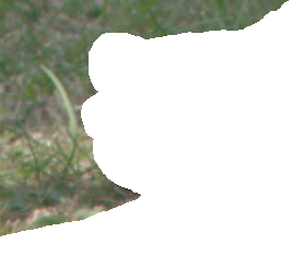
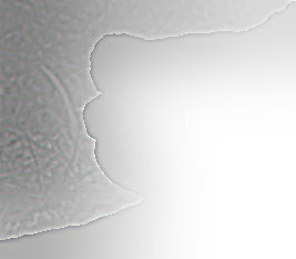
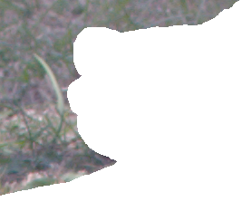
toes_holed.png
set SRC=toes_holed.png
Images with transparency need special processing when making Laplacian pyramids.
This page builds on material in:
Related material appears in:
The sample image has a large area with full transparency.
|
toes_holed.png set SRC=toes_holed.png |
|
When an image has transparency, we can build and collapse image pyramids with ImageMagick's ordinary processing, so the down-sizing process will blur low-frequency alpha. For a Gaussian pyramid, this is not a problem. For a Laplacian pyramid, enlarging the grids will blur transparency into areas that should be opaque. For ordinary photographs, low-frequency grids carry most of the colour information. When collapsed, these low-frequency pixels will contribute too little to the final result, so parts of the image will have lower saturation than they should have and may also be colour-shifted.
Hence, the round-trip of building then collapsing a Laplacian pyramid does not reconstruct the original.
To illustrate the problem, we build a Laplacian pyramid of the sample image, then collapse it, and compare with the original.
Without the mkpKEEP_ALPHA_RES setting:
set mkpDEBUG=1
set mkpHTM=1
set pyWR_VAR=1
set pyPREFIX=la_p1_

set mkpKEEP_ALPHA_RES=
call %PICTBAT%mkLapPyr %SRC% la_p1.tiff

set pyWR_VAR=
%IM%identify la_p1.tiff
la_p1.tiff[0] TIFF 267x233 267x233+0+0 16-bit sRGB 305KB 0.000u 0:00.000
la_p1.tiff[1] TIFF 134x117 134x117+0+0 16-bit sRGB 305KB 0.016u 0:00.007
la_p1.tiff[2] TIFF 67x58 67x58+0+0 16-bit sRGB 305KB 0.016u 0:00.009
la_p1.tiff[3] TIFF 33x29 33x29+0+0 16-bit sRGB 305KB 0.016u 0:00.009
la_p1.tiff[4] TIFF 17x15 17x15+0+0 16-bit sRGB 305KB 0.016u 0:00.009
la_p1.tiff[5] TIFF 8x7 8x7+0+0 16-bit sRGB 305KB 0.016u 0:00.009
la_p1.tiff[6] TIFF 4x4 4x4+0+0 16-bit sRGB 305KB 0.016u 0:00.009
la_p1.tiff[7] TIFF 267x233 267x233+0+0 16-bit Grayscale Gray 305KB 0.016u 0:00.009
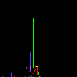
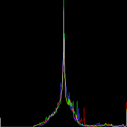
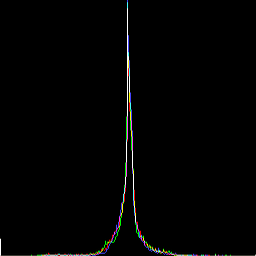
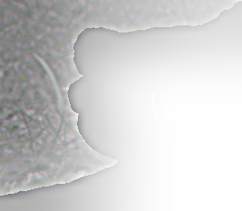
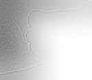
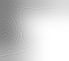
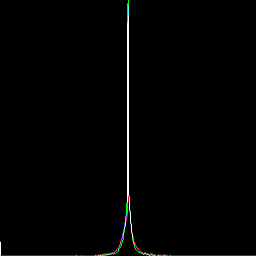
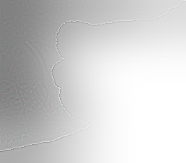
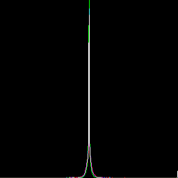
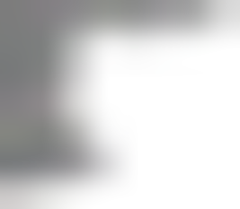
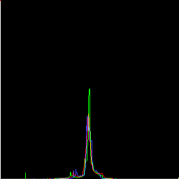
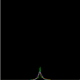
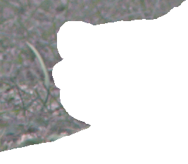
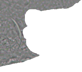
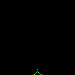
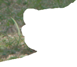
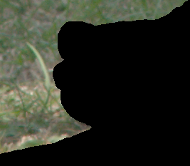
| Octave | Grid | Grid, resized up | Histogram of resized grid | Difference |
|---|---|---|---|---|
| 6 |
|

|
|

|
| 5 |
|

|
|
|
| 4 |
|
|
|
|
| 3 |
|
|
|
|
| 2 |

|
|
|
|
| 1 |
|
|
|

|
| 0 |

|
|
|

|
%IM%identify -format "min=%%[fx:minima] max=%%[fx:maxima]" la_p1.tiff[%mklpNUM_OCTAVES%]
min=0 max=1
%IM%convert ^
  @la_p1_mklp_recon.scr ^
  la_recon_l1.png

%IM%compare ^
  -metric RMSE ^
  %SRC% ^
  la_recon_l1.png ^
  NULL: >la_comp1.lis 2^>^&1
19883.1 (0.303397) |
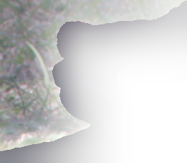
|
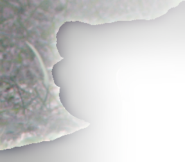
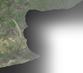
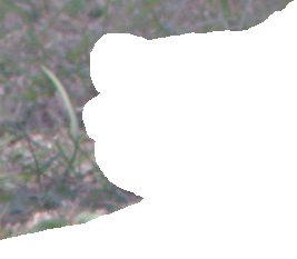
The area that was fully transparent and the area that was fully opaque have both become partially transparent. This isn't a major problem, as we could restore the correct alpha. But the area that should be opaque has also suffered changes to the colour values. This is a serious problem.
When building the pyramid, we save a copy of the image's alpha channel. After subtracting the enlarged grid from the input, we copy the saved alpha into the result. Hence, each difference will have the same alpha as the source. This ensures that blurred alpha is not propagated to the lower levels of the pyramid.
When collapsing the pyramid, we replace the alpha of each enlarged grid with the alpha from the final difference.
The extra processing carries a (small) cost, so is not enabled by default. If you want it, set mkpKEEP_ALPHA_RES=1. This modifies the behaviour of mkLapPyr.bat, so the pyramid will be built with alpha at full resolution, and the _recon script that collapses the pyramid will also use the full resolution.
set mkpDEBUG=1
set mkpHTM=1
set pyWR_VAR=1
set pyPREFIX=la_p2_

set mkpKEEP_ALPHA_RES=1
call %PICTBAT%mkLapPyr %SRC% la_p2.tiff
set mkpKEEP_ALPHA_RES=

set pyWR_VAR=
%IM%identify la_p2.tiff
la_p2.tiff[0] TIFF 267x233 267x233+0+0 16-bit sRGB 158KB 0.016u 0:00.000
la_p2.tiff[1] TIFF 134x117 134x117+0+0 16-bit sRGB 158KB 0.000u 0:00.007
la_p2.tiff[2] TIFF 67x58 67x58+0+0 16-bit sRGB 158KB 0.000u 0:00.007
la_p2.tiff[3] TIFF 33x29 33x29+0+0 16-bit sRGB 158KB 0.000u 0:00.009
la_p2.tiff[4] TIFF 17x15 17x15+0+0 16-bit sRGB 158KB 0.000u 0:00.009
la_p2.tiff[5] TIFF 8x7 8x7+0+0 16-bit sRGB 158KB 0.000u 0:00.009
la_p2.tiff[6] TIFF 4x4 4x4+0+0 16-bit sRGB 158KB 0.000u 0:00.009
la_p2.tiff[7] TIFF 267x233 267x233+0+0 16-bit Grayscale Gray 158KB 0.000u 0:00.009
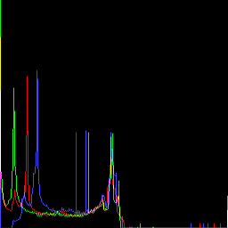
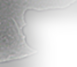
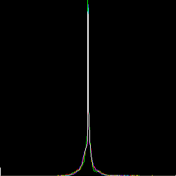
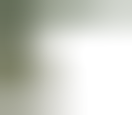
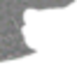
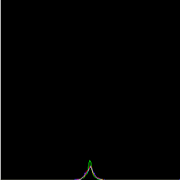
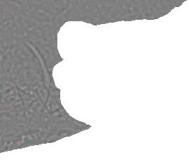
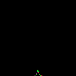
| Octave | Grid | Grid, resized up | Histogram of resized grid | Difference |
|---|---|---|---|---|
| 6 |
|
|

|
|
| 5 |
|
|
|
|
| 4 |
|

|
|
|
| 3 |
|
|
|
|
| 2 |

|

|
|
|
| 1 |

|

|
|

|
| 0 |
|

|
|

|
%IM%identify -format "min=%%[fx:minima] max=%%[fx:maxima]" la_p2.tiff[%mklpNUM_OCTAVES%]
min=0 max=0.500008
%IM%convert ^
  @la_p2_mklp_recon.scr ^
  la_recon_l2.png

%IM%compare ^
  -metric RMSE ^
  %SRC% ^
  la_recon_l2.png ^
  NULL: >la_comp2.lis 2^>^&1
8.12559 (0.000123989) |
|
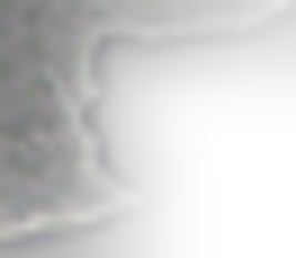
The reconstruction is an almost perfect copy of the input.
%IM%convert ^
  ( la_recon_l2.png ^
    -channel A -threshold 0 +channel ^
    -background Black -layers flatten ^
    +write la_cmp1.png ^
  ) ^
  ( toes_holed.png ^
    -background Black -layers flatten ^
    +write la_cmp2.png ^
  ) ^
  -metric RMSE -format %%[distortion] -compare ^
  info:
0.00014317 |

|
I expect this method (with set mkpKEEP_ALPHA_RES=1 on a Laplacian of an image with transparency) is similar to using a Laplacian of an opaque image with a Gaussian of the mask. It may not be identical.
See also Blending pyramids.
We can use any method from Filling holes to fill holes in each grid, then collapse the resulting pyramid.
First, we make a copy of the pyramid, and work from that copy:
copy /y la_p2.tiff la_p2_save.tiff
Each example walks through all levels of the pyramid: the grids plus the final difference. Each level is written to f_N.tiff which are converted to a single TIFF file la_p2_XXN.tiff.
sed is a Unix utility, available on Windows from Cygwin. We use it to make a copy of the _recon script, changing the pyramid filename. Then we run that script to collapse the pyramid and make an output image.
Mean fillset FILE_LIST= for /L %%i in (0,1,%mklpNUM_OCTAVES%) do ( call %PICTBAT%meanFill la_p2_save.tiff[%%i] f_%%i.tiff set FILE_LIST=!FILE_LIST! f_%%i.tiff ) %IM%convert %FILE_LIST% la_p2_mf.tiff sed -e 's/la_p2/la_p2_mf/g' la_p2_mklp_recon.scr >la_recon.scr %IM%convert @la_recon.scr la_mf.png This method isn't successful by itself,
|
|
Shift fillset FILE_LIST= for /L %%i in (0,1,%mklpNUM_OCTAVES%) do ( call %PICTBAT%shiftFill la_p2_save.tiff[%%i] . f_%%i.tiff set FILE_LIST=!FILE_LIST! f_%%i.tiff ) %IM%convert %FILE_LIST% la_p2_sf.tiff sed -e 's/la_p2/la_p2_sf/g' la_p2_mklp_recon.scr >la_recon.scr %IM%convert @la_recon.scr la_sf.png |
|
Blur fillset FILE_LIST= for /L %%i in (0,1,%mklpNUM_OCTAVES%) do ( call %PICTBAT%blurFill la_p2_save.tiff[%%i] . f_%%i.tiff if "%bfBUST%"=="1" call %PICTBAT%meanFill f_%%i.tiff f_%%i.tiff set FILE_LIST=!FILE_LIST! f_%%i.tiff ) %IM%convert %FILE_LIST% la_p2_bf.tiff sed -e 's/la_p2/la_p2_bf/g' la_p2_mklp_recon.scr >la_recon.scr %IM%convert @la_recon.scr la_bf.png |

|
Resize fill, defaultset FILE_LIST= for /L %%i in (0,1,%mklpNUM_OCTAVES%) do ( call %PICTBAT%resizeFill la_p2_save.tiff[%%i] . f_%%i.tiff call %PICTBAT%meanFill f_%%i.tiff f_%%i.tiff set FILE_LIST=!FILE_LIST! f_%%i.tiff ) %IM%convert %FILE_LIST% la_p2_rf2.tiff sed -e 's/la_p2/la_p2_rf2/g' la_p2_mklp_recon.scr >la_recon.scr %IM%convert @la_recon.scr la_rf2.png |
|
Resize fill, 1.1set FILE_LIST= for /L %%i in (0,1,%mklpNUM_OCTAVES%) do ( call %PICTBAT%resizeFill la_p2_save.tiff[%%i] 1.1 f_%%i.tiff call %PICTBAT%meanFill f_%%i.tiff f_%%i.tiff set FILE_LIST=!FILE_LIST! f_%%i.tiff ) %IM%convert %FILE_LIST% la_p2_rf.tiff sed -e 's/la_p2/la_p2_rf/g' la_p2_mklp_recon.scr >la_recon.scr %IM%convert @la_recon.scr la_rf.png |
|
Process module fillholesset FILE_LIST=
for /L %%i in (0,1,%mklpNUM_OCTAVES%) do (
%IMDEV%convert ^
la_p2_save.tiff[%%i] ^
-channel A -threshold 50%% +channel ^
-process 'fillholes wr 5 lsr 5%% v' ^
-process 'fillholes wr 4 lsr 25%% v' ^
-process 'fillholes wr 3 v' ^
-process 'fillholes wr 1 v' ^
f_%%i.tiff
call %PICTBAT%meanFill f_%%i.tiff f_%%i.tiff
set FILE_LIST=!FILE_LIST! f_%%i.tiff
)
%IM%convert %FILE_LIST% la_p2_fh.tiff
sed -e 's/la_p2/la_p2_fh/g' la_p2_mklp_recon.scr >la_recon.scr
%IM%convert @la_recon.scr la_fh.png
|
|
Fractal noise displacement mapset FILE_LIST=
for /L %%i in (0,1,%mklpNUM_OCTAVES%) do (
call %PICTBAT%fnDispFill ^
la_p2_save.tiff[%%i] ^
f_%%i.tiff
if "!fndfBUST!"=="1" call %PICTBAT%meanFill f_%%i.tiff f_%%i.tiff
set FILE_LIST=!FILE_LIST! f_%%i.tiff
)
%IM%convert %FILE_LIST% la_p2_fndf.tiff
sed -e 's/la_p2/la_p2_fndf/g' la_p2_mklp_recon.scr >la_recon.scr
%IM%convert @la_recon.scr la_fndf.png
|
|
The resizeFill.bat technique uses a single convert command to build a Gaussian pyramid, then collapse by enlarging the grids (as usual) but then merging the layers over each other, instead of adding them. The example above applies this technique to all the grids of a Laplacian pyramid, so we are making Gaussian pyramids from every layer of a Laplacian pyramid.
Applying a hole-filling technique to a Laplacian pyramid has some benefits over applying it to the simple image:
The only drawback of applying techniques to pyramids seems to be in processing time. The quality always seems to be improved.
All images on this page were created by the commands shown, using:
%IM%identify -version
Version: ImageMagick 6.9.2-5 Q16 x64 2015-10-31 http://www.imagemagick.org
Copyright: Copyright (C) 1999-2015 ImageMagick Studio LLC
License: http://www.imagemagick.org/script/license.php
Visual C++: 180031101
Features: Cipher DPC Modules OpenMP
Delegates (built-in): bzlib cairo freetype jng jp2 jpeg lcms lqr openexr pangocairo png ps rsvg tiff webp xml zlib
Source file for this web page is lapalph.h1. To re-create this web page, execute "procH1 lapalph".
This page, including the images, is my copyright. Anyone is permitted to use or adapt any of the code, scripts or images for any purpose, including commercial use.
Anyone is permitted to re-publish this page, but only for non-commercial use.
Anyone is permitted to link to this page, including for commercial use.
Page version v1.0 24-Oct-2015.
Page created 23-Apr-2016 02:13:59.
Copyright © 2016 Alan Gibson.