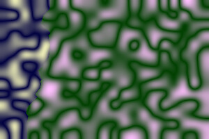
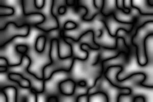
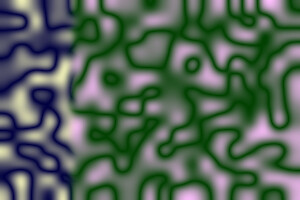
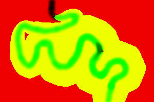
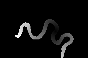
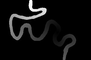
meand3.png
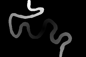
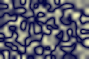
Dark paths solve some minimization problems, and create sequences for animation and other purposes.
Here are fuller explanations and some usage examples of process modules that find the darkest paths between image edges: find darkest path, find darkest meandering path and find darkest path between two points.
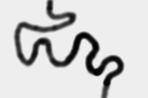
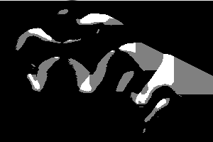
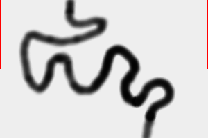
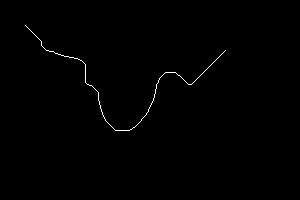
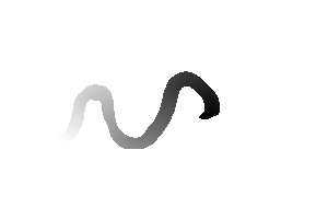
In Gimp, I airbrush a black line on a light-gray background.
|
meand3.png |
|
The process module darkestpath is based on an algorithm in Image Quilting for Texture Synthesis and Transfer, Alexei A. Efros and William T. Freeman, 2001. The algorithm is short, elegant, fast (eg 1.5s for a 7000x5000 pixel image), and provably correct. However, it defines "path" in a narrow sense.
| Option | Description | |
|---|---|---|
| Short
form |
Long form | |
| c | cumerr | Write cumulative error image instead of path image. |
| v | verbose | Write some text output to stderr. |
The code is fast because it traverses the entire image just once to make the cumulative, then four pixels per row to find the path. It always finds a path, and it will be a minimum.
The values used are the pixel intensities, as defined by the current -intensity setting.
In versions before 21-May-2016, the code read only the red channel of the input image, and the cumulation was stored in the red channel of a second image.
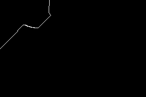
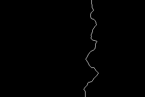
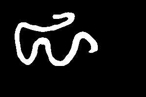
The path is written to a third image, entirely black, but with white pixels marking the path.
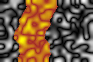
By default, the module returns the path image. If the cumul option is selected, the cumulative image is returned instead.
The algorithm and the darkestpath module will not make a path that is more shallow than 45°. The path image will contain exactly one white pixel per row. The path is always between the top and bottom. If it is wanted between the left and right sides, rotation can be used before and after calling the module.
If a path is wanted between adjacent sides, such as between the top and the left side, two paths can be created, one vertical and the other horizontal, and the appropriate arms from each are used. This is likely to be sub-optimal, but "good enough". This is commonly used, eg for Tiling with dark paths, Rectangle boundaries with dark paths and Quilting.
%IM7DEV%magick ^
meand3.png ^
-colorspace sRGB ^
( +clone ^
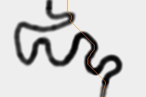
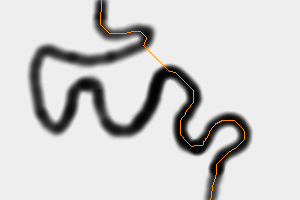
-process 'darkestpath' ^
-fill #f80 -opaque White ^
-transparent Black ^
) ^
-composite ^
dp_dp1.png
|
|
%IM7DEV%magick ^
meand3.png ^
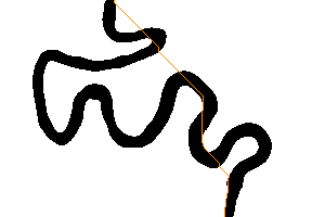
-threshold 50%% ^
-colorspace sRGB ^
( +clone ^
-process 'darkestpath' ^
-fill #f80 -opaque White ^
-transparent Black ^
) ^
-composite ^
dp_dp2.png
|
|
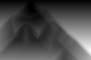
%IM7DEV%magick ^ meand3.png ^ -colorspace sRGB ^ -threshold 50%% ^ -process 'darkestpath c' ^ -channel RGB -auto-level +channel ^ dp_dpc2.png |
|
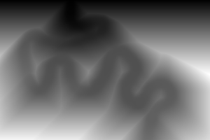
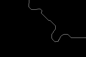
The process module darkestmeander is an extension of Darkest path above. It starts by building the same cumulative image. It then iterates, refining the cumulation, in the four directions. At each of these passes, the minimum is taken from five pixels: the three "above" and the ones on each "side", though these directions are relative to the orientation of the pass.
The code stops the iteration of the cumulatives when any of these conditions becomes true:
Condition (3) is the only perfect end, but large photographs are very slow to converge. The autoiter option slightly slows processing, as the path must be calculated after every cycle, but this should be hardly measurable.
Areas of black in the input image would cause a difficulty as they would cumulate to the same value, so finding the path from the cumulative might not be possible. (The path may be circular.) For this reason, the code initially ensures that every input pixel that is zero in the red channel is changed to "1" (on a scale of zero to QuantumRange).
Darkestpath doesn't suffer from this problem because a pixel's parent is certainly in the previous row. If the three possible parents have equal values, any could be chosen.
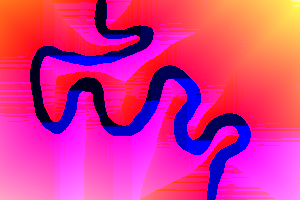
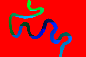
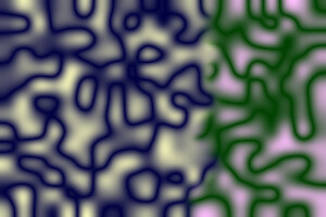
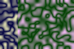
When calculating cumulatives, the green and blue channels are used to store the y- and x-offset of the parent of each pixel. This makes path traversal fast as we don't need to find the minimum of eight neighbours, but the cost is maintaining these pointers at every pixel, during every pass, and most of the effort is wasted. I may remove this. (However, I do like the pretty colour images this makes.)
| Option | Description | |
|---|---|---|
| Short
form |
Long form | |
| m N | maxiter N | Maximum number of iterations of each cycle.
0 = no limit. Default = 10. |
| a | autoiter | Stop iterating when path becomes stable. |
| c | cumulerr | Return cumulative image instead of path image. |
| s string | side string | Which sides to search for the minimum cumulative.
String may have one or more of LBRlbr for left side, bottom or right side. Default = b. |
| e X,Y | end_at X,Y | Find the path that ends at given X,Y coordinate. |
| v | verbose | Write some text output to stderr. |
| v2 | verbose2 | Write more text output to stderr. |
Options maxiter and autoiter are independent, and both can be used.
Temporarily, "-process 'darkestmeander'" doesn't work, so skip it.
rem goto skipMeander

%IM7DEV%magick ^
  -size 300x200 xc:gray(50%%) ^
  -colorspace sRGB ^
  ( +clone ^
    -process 'darkestmeander' ^
    -fill #f80 -opaque White ^
    -transparent Black ^
  ) ^
  -composite ^
  dp_mp_gr1.png
|

|
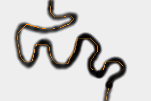
%IM7DEV%magick ^
  meand3.png ^
  -colorspace sRGB ^
  ( +clone ^
    -process 'darkestmeander' ^
    -fill #f80 -opaque White ^
    -transparent Black ^
  ) ^
  -composite ^
  dp_mp1.png
|
|
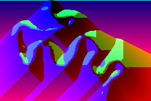
%IM7DEV%magick ^ meand3.png ^ -colorspace sRGB ^ -process 'darkestmeander c' ^ -channel R -separate +channel ^ -auto-level ^ dp_mp1c.png |
|
%IM7DEV%magick ^
  meand3.png ^
  -level 30%%,70%% ^
  -colorspace sRGB ^
  ( +clone ^
    -process 'darkestmeander a v2' ^
    -fill #f80 -opaque White ^
    -transparent Black ^
  ) ^
  -composite ^
  dp_mp2.png
|
|
%IM7DEV%magick ^ meand3.png ^ -level 30%,70%% ^ -colorspace sRGB ^ -process 'darkestmeander c a' ^ -channel RGB -auto-level +channel ^ +depth ^ +write dp_mpc3.png ^ -separate ^ dp_mpc3.png |


|
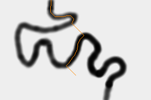
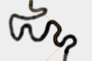
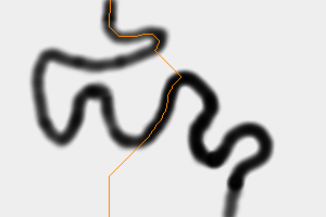
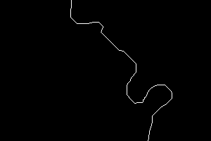
By default, the module finds the darkest path starting at the top edge and ending at the bottom edge. The side option finds a path that ends at the given edge(s). Instead, the end_at option can be used to find the path that ends at any coordinate. This can be any coordinate on an edge or within the image. It is a fatal error if the coordinate is outside the image.
%IM7DEV%magick ^
  meand3.png ^
  -colorspace sRGB ^
  ( +clone ^
    -process 'darkestmeander a end_at 150,150' ^
    -fill #f80 -opaque White ^
    -transparent Black ^
  ) ^
  -composite ^
  dp_ea1.png
|
|
%IM7DEV%magick ^
  meand3.png ^
  -colorspace sRGB ^
  ( +clone ^
    -process 'darkestmeander a end_at 150,199' ^
    -fill #f80 -opaque White ^
    -transparent Black ^
  ) ^
  -composite ^
  dp_ea2.png
|
|
%IM7DEV%magick ^
  meand3.png ^
  -colorspace sRGB ^
  ( +clone ^
    -process 'darkestmeander a end_at 100,199' ^
    -fill #f80 -opaque White ^
    -transparent Black ^
  ) ^
  -composite ^
  dp_ea3.png
|
|
An alternative strategy is to discourage the path from straying into the white areas by making them very white, so a path through them would be extremely light.
%IM7DEV%magick ^
  meand3.png ^
  -colorspace sRGB ^
  ( +clone ^
    -auto-level ^
    -fuzz 10%% ^
    -fill rgb(100000%%,100000%%,100000%%) ^
    -opaque white ^
    -process 'darkestmeander a v2' ^
    -fill #f80 -opaque White ^
    -transparent Black ^
  ) ^
  -composite ^
  dp_mp2.png
|
|
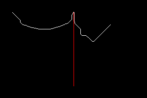
Finding the path from the top row to either side will usually create a very short path, of a single pixel. This is because the top corner pixels are contained in both the top row, and the side columns, and this will often be the path with the darkest sum.
To influence the path found, we can paint super-red lines at each side. "Super-red" means a colour that has zero in the green and blue channels, but more than 100% in the red channel. I choose a factor of 10,000. A path containing a single pixel of this colour will be lighter than any path containing ordinary colours, so it won't be found by the algorithm.
This technique requires that IM is compiled with HDRI. (But these process modules should generally be used only with HDRI.)
|
Make an image with super-red lines. %IM7DEV%magick ^
meand3.png ^
-colorspace sRGB ^
-define compose:clamp=off ^
( -clone 0 ^
-crop 1x+0+0 -crop 100%%x50%%+0+0 +repage ^
-fill Red -colorize 100 ^
-evaluate Multiply 10000 ^
+write mpr:SUP ^
) ^
-gravity NorthWest -composite ^
mpr:SUP ^
-gravity NorthEast -composite ^
-define quantum:format=floating-point ^
dp_sw1.tiff
Verify the super-red: %IM7DEV%magick identify ^ -format "MIN=%%[fx:minima] MAX=%%[fx:maxima]" ^ dp_sw1.tiff MIN=0 MAX=10000 |
|
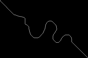
%IM7DEV%magick ^ dp_sw1.tiff ^ -process 'darkestmeander m 0 a side l' ^ dp_sidel.png |
|
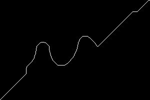
%IM7DEV%magick ^ dp_sw1.tiff ^ -process 'darkestmeander m 0 a side r' ^ dp_sider.png |
|
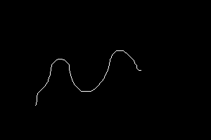
%IM7DEV%magick ^ dp_sw1.tiff ^ -process 'darkestmeander m 0 a side lbr' ^ dp_sidelbr.png |
|
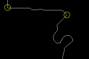
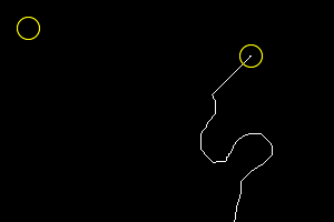
We can build super-white fences horizontally across the width of the image, with a hole in each fence. This forces the path to pass through the gate. In the output image I circle the gate positions in yellow.
rem setlocal rem set IMG7=%IM7DEV% call %PICTBAT%supWhGate ^ dp_sw1.tiff 25 25 dp_sw1swg.tiff if ERRORLEVEL 1 exit /B 1 call %PICTBAT%supWhGate ^ dp_sw1swg.tiff 225 50 dp_sw1swg.tiff if ERRORLEVEL 1 exit /B 1 rem endlocal %IM7DEV%magick ^ dp_sw1swg.tiff ^ -process 'darkestmeander m 0 a' ^ -stroke Yellow -fill None ^ -draw "translate 225,50 circle 0,0 0,10" ^ -draw "translate 25,25 circle 0,0 0,10" ^ dp_swg1.png |
|
This section is experimental.
With HDRI, colours can be negative. A negative colour is cumulated in the same way as positive colours. They will "soak up" cumulations from positive colours, creating a lower sum for that path. When a very strongly negative colour is used, any path that passes through it will have a lower (more negative) sum than paths that include only ordinary colours. Hence, the found path will pass through this point.
(We might say the negative colour acts as a black hole, sucking the lightness from paths. It is a gravity well, ensuring that all paths travel through it.)
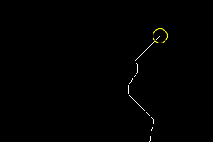
For example, we can force the path to pass through coordinate 225,50. In the output image, I also circle this coordinate.
%IM7DEV%magick ^ dp_sw1.tiff ^ -fill rgb(-1000000%%,0,0) ^ -draw 'point 225,50' ^ -process 'darkestpath v' ^ -stroke Yellow -fill None ^ -draw "translate 225,50 circle 0,0 0,10" ^ dp_supbl.png |
|
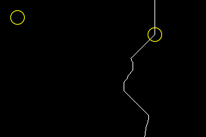
However, there is a major problem. When some pixels are negative, the darkest path may be to traverse these pixels repeatedly. The more times the pixels are traversed, the darker the path becomes. There is no lower bound on the problem. My process module detects these cycles, and stops processing. There is probably a better approach to negative values.
%IM7DEV%magick ^ dp_sw1.tiff ^ -fill rgb(-1000000%%,0,0) ^ -draw 'point 225,50' ^ -draw 'point 25,25' ^ -process 'darkestpath' ^ -stroke Yellow -fill None ^ -draw "translate 225,50 circle 0,0 0,10" ^ -draw "translate 25,25 circle 0,0 0,10" ^ dp_supbl2.png |
|
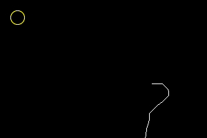
%IM7DEV%magick ^ dp_sw1.tiff ^ -fill rgb(-1000000%%,0,0) ^ -draw 'point 25,25' ^ -process 'darkestmeander m 100 a' ^ -stroke Yellow -fill None ^ -draw "translate 25,25 circle 0,0 0,10" ^ dp_supbl3.png |

|
%IM7DEV%magick ^ dp_sw1.tiff ^ -precision 20 ^ -evaluate max 1 ^ -format "%%[fx:minima] %%[fx:maxima]\n" +write info: ^ -fill rgb(-1000000%%,0,0) ^ -draw 'point 25,25' ^ -format "%%[fx:minima] %%[fx:maxima]\n" +write info: ^ -process 'darkestmeander m 300 a' ^ -format "%%[fx:minima] %%[fx:maxima]\n" +write info: ^ -stroke Yellow -fill None ^ -draw "translate 25,25 circle 0,0 0,10" ^ dp_supbl3a.png |
|
%IM7DEV%magick ^ dp_sw1.tiff ^ -fill rgb(-1000%%,0,0) ^ -draw 'point 225,50' ^ -draw 'point 25,25' ^ -process 'darkestmeander m 100 a' ^ -stroke Yellow -fill None ^ -draw "translate 225,50 circle 0,0 0,10" ^ -draw "translate 25,25 circle 0,0 0,10" ^ dp_supbl4.png :skipMeander |
|
The process module darkestpntpnt implements Dijkstra's algorithm for the shortest path between two points. The measure used here for distance is the total intensity along the path.
| Option | Description | |
|---|---|---|
| Short
form |
Long form | |
| s X,Y | start_at X,Y | Start the path at this coordinate.
Default 0,0. |
| e X,Y | end_at X,Y | End the path at this coordinate.
Default 0,0. |
| t N | threshold_visited N | Pixels with an intensity greater than this will not be visited. Generally 0.0 < N <= 1.0 |
| n | no_end | Don't stop processing at path end. |
| d | data | Write data image instead of path image. |
| p | Write each visited coordinate to stderr. | |
| v | verbose | Write some text output to stderr. |
See:
See also Mosaicking of Aerial Photographic Maps Via Seams Defined by Bottleneck Shortest Paths Fernandez, E., Garfinkel, R. & Roman Arbiol (1998).
The basic algorithm is short, simple, easy to implement and provably correct. It is also slow, so the code also uses a priority queue (implemented as a self-balancing binary tree, which itself is implemented in an array) to reduce the time to process a 7000x5000 pixel image from over ten hours to around six seconds. A different priority queue might improve performance further.
In Q32 HDRI, the module takes 40 bytes of memory per pixel. The module uses internal data structures for processing, rather than temporary images, so it does not need HDRI.
The module uses the current -intensity setting to determine the lightness.
The threshold_visited option has two purposes:
If the start or end pixel is above the threshold, no path will be found. The module will report this to stderr.
%IM7DEV%magick xc:White -process 'darkestpntpnt t 0.5' x.png >dp_prob.lis 2>&1
Problem: start pixel has value (1) above threshold.
Problem: end pixel has value (1) above threshold.
By default, processing stops when the shortest path from the start to the end has been found. If you want to continue until no more pixels can be processed, use no_end. This will increase processing time.
When the verbose option is used, the text output (to stderr) will include a line like:
nInPath: 1234
The integer is the number of pixels that have been found on the path.
|
Default start and end at (0,0)
%IM7DEV%magick ^ meand3.png ^ -colorspace sRGB ^ -process darkestpntpnt ^ dp_pp1.png |

|
%IM7DEV%magick ^
  meand3.png ^
  -colorspace sRGB ^
  -process ^
    'darkestpntpnt start_at 0,0 end_at 299,199' ^
  dp_pp2.png
|
|
%IM7DEV%magick ^ meand3.png ^ -colorspace sRGB ^ -process 'darkestpntpnt s 1p,0 e 0,1p' ^ dp_pp3.png |
|
%IM7DEV%magick ^ meand3.png ^ -colorspace sRGB ^ -process 'darkestpntpnt s 200,100 e 50,150' ^ dp_pp4.png |
|
%IM7DEV%magick ^ meand3.png ^ -colorspace sRGB ^ -process 'darkestpntpnt s 225,50 e 25,25' ^ dp_pp5.png |
|
|
Paint a 200% white line on the picture,
%IM7DEV%magick ^ meand3.png ^ -colorspace sRGB ^ -stroke gray(200%%) ^ -draw "line 150,25 150,175" ^ -process 'darkestpntpnt s 225,50 e 25,25 t 1.5' ^ -stroke red ^ -draw "line 150,25 150,175" ^ dp_pp6.png |
|
If the data option is used, the process will populate the red green and blue channels of the output image with contain data about the processs. At each pixel:
If the line is entirely black, the intensities will be zero, so the sum of intensities from the start to any point will also be zero. If we want a gradient, we need non-zero values. In the following, we set any zero channels into one (on a scale of zero to quantum). This should work for HDRI or non-HDRI.
However, in many cases, the sum of the intensities will exceed quantum, so HDRI should generally be used.
|
Make a pretty picture. %IM7DEV%magick ^
meand3.png ^
-threshold 50%% ^
-colorspace sRGB ^
-evaluate Subtract 1 -clamp -evaluate Add 1 ^
-process ^
'darkestpntpnt s 50c,50c no_end data' ^
-channel RGB -auto-level +channel ^
dp_ppd1.png
|
|
|
Don't find a path through pixels lighter than 0.5 (on scale of 0.0 to 1.0). %IM7DEV%magick ^
meand3.png ^
-threshold 50%% ^
-colorspace sRGB ^
-evaluate Subtract 1 -clamp -evaluate Add 1 ^
-process ^
'darkestpntpnt s 50c,50c t 0.5 no_end data' ^
-channel RGB -auto-level +channel ^
dp_ppd2.png
|
|
|
Create a gradient along the line,
%IM7DEV%magick ^
  meand3.png ^
  -threshold 50%% ^
  -colorspace sRGB ^
  -evaluate Subtract 1 -clamp -evaluate Add 1 ^
  -process ^
    'darkestpntpnt s 50c,50c t 0.5 no_end data verbose' ^
  -clamp ^
  -channel G -separate +channel ^
  -auto-level ^
  dp_ppd3.png >dp_ppd3.lis 2>&1
darkestpntpnt options: start_at 50c,50c end_at 0,0 threshold_visited 0.5 data no_end verbose Problem: end pixel has value (1) above threshold. nVisited: 8366 nInPath: 8366 maxDist: 394.67619 maxDistPc: 9.1892711e-06 writeData. |
|
The verbose output tells us how many pixels were found, and the maximum distance from the start.
For more examples, see Application: gradient lines below.
If we want to place one image over another, cutting off part of the upper image to reveal some of the lower image, how do we make the cut so the join is not obvious?
Answer: we find a line that minimizes the difference.
See Overlapping photographs: Minimum error boundary cut.
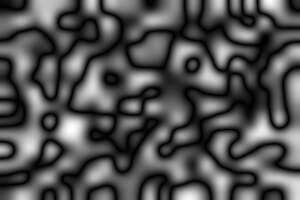
%IMG7%magick ^ -size 21x14 xc: ^ -seed 1234 ^ +noise Random ^ -channel R -separate +channel ^ -resize "300x200^!" ^ -solarize 50%% -negate -auto-level ^ +write dp_src2.png ^ -channel G +level 25%%,75%% +channel ^ dp_src2_c.png |
|
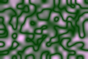
%IMG7%magick ^ -size 21x14 xc: ^ -seed 2345 ^ +noise Random ^ -channel R -separate +channel ^ -resize "300x200^!" ^ -solarize 50%% -negate -auto-level ^ +write dp_src3.png ^ -channel B +level 25%%,75%% +channel ^ dp_src3_c.png |
|
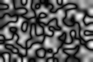
Create a difference image (also known as an "error" image):
%IMG7%magick ^ dp_src2.png ^ dp_src3.png ^ -compose Difference -composite ^ dp_sdiff.png |
|
From the difference image, find the darkest path and meander, and turn these into masks:
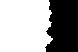
%IM7DEV%magick ^ dp_sdiff.png ^ -process 'darkestpath' ^ +write dp_sdp.png ^ -fill White -draw 'color 0,0 floodfill' ^ dp_sdp_msk.png |


|
goto skipSdmMsk %IM7DEV%magick ^ dp_sdiff.png ^ -process 'darkestmeander a' ^ +write dp_sdm.png ^ -fill White -draw 'color 0,0 floodfill' ^ dp_sdm_msk.png :skipSdmMsk |
|
Composite the grayscale and colour versions with these masks:
%IMG7%magick ^ dp_src2.png ^ dp_src3.png ^ dp_sdp_msk.png ^ -composite ^ dp_sdp_23.png |

|
%IMG7%magick ^ dp_src2_c.png ^ dp_src3_c.png ^ dp_sdp_msk.png ^ -composite ^ dp_sdp_23_c.png |
|
%IMG7%magick ^ dp_src2.png ^ dp_src3.png ^ dp_sdm_msk.png ^ -composite ^ dp_sdm_23.png |
|
%IMG7%magick ^ dp_src2_c.png ^ dp_src3_c.png ^ dp_sdm_msk.png ^ -composite ^ dp_sdm_23_c.png |

|
As above, but blurring the masks to roughly the same degree as the images:
set BLR=-blur 0x4
%IMG7%magick ^
  dp_src2.png ^
  dp_src3.png ^
  ( dp_sdp_msk.png ^
    %BLR% )^
  -composite ^
  dp_sdp_23b.png
|
|
%IMG7%magick ^
  dp_src2_c.png ^
  dp_src3_c.png ^
  ( dp_sdp_msk.png ^
    %BLR% )^
  -composite ^
  dp_sdp_23_cb.png
|
|
%IMG7%magick ^
  dp_src2.png ^
  dp_src3.png ^
  ( dp_sdm_msk.png ^
    %BLR% )^
  -composite ^
  dp_sdm_23b.png
|
|
%IMG7%magick ^
  dp_src2_c.png ^
  dp_src3_c.png ^
  ( dp_sdm_msk.png ^
    %BLR% )^
  -composite ^
  dp_sdm_23_cb.png
|
|
With the blur, darkestpath and darkestmeander are both acceptable, though I think the meander is slightly better.
For comparison, we make a cut line at the column with the minimum difference:
|
The darkest column from the difference: %IMG7%magick ^ dp_sdiff.png ^ -scale "300x1^!" ^ -scale "300x200^!" ^ -auto-level ^ -fill White +opaque Black ^ -negate ^ +write dp_col.png ^ -fill White -draw "color 0,0 floodfill" ^ dp_col_msk.png |


|
With this mask, we make the cuts:
%IMG7%magick ^ dp_src2.png ^ dp_src3.png ^ ( dp_col_msk.png ^ )^ -composite ^ dp_col_23.png |

|
%IMG7%magick ^ dp_src2_c.png ^ dp_src3_c.png ^ ( dp_col_msk.png ^ )^ -composite ^ dp_col_23_c.png |
|
%IMG7%magick ^ dp_src2.png ^ dp_src3.png ^ ( dp_col_msk.png ^ %BLR% )^ -composite ^ dp_col_23b.png |
|
%IMG7%magick ^
  dp_src2_c.png ^
  dp_src3_c.png ^
  ( dp_col_msk.png ^
    %BLR% )^
  -composite ^
  dp_col_23_cb.png
|
|
Even with the blur, darkest column is not acceptable.
Suppose we want to reduce the width of an image by "tearing out" a piece from the middle, such that the cut-line on both sides is the same, and the line is the least-obvious one we can make. (Also known as "liquid rescaling".)
We overlap the piece with itself, offset by the required reduction in width. Find the difference, and the darkest path down that difference. For example, we reduce dp_src2.png by 100 pixels.
%IMG7%magick ^ dp_src2.png ^ ( +clone ) ^ -geometry +100+0 ^ -compose Difference -composite ^ -crop +100+0 +repage ^ dp_sc1.png |

|
%IM7DEV%magick ^ dp_sc1.png ^ -process darkestpath ^ -fill White ^ -draw "color 0,0 floodfill" ^ dp_sc1dp.png |
|
%IMG7%magick ^
  dp_src2.png ^
  ( +clone ^
    dp_sc1dp.png ^
    -alpha off ^
    -compose CopyOpacity -composite ^
  ) ^
  -geometry +100+0 ^
  -compose Over -composite ^
  -crop +100+0 +repage ^
  dp_sc_out.png
|

|
|
For comparison, the uncut dp_src2.png |

|
%IMG7%magick ^ dp_sc1dp.png ^ -negate ^ ( +clone -negate -set page +100+0 ) ^ -compose Darken -layers mosaic ^ -negate ^ dp_sc_lm.png |
|
|
Highlight the piece we have removed. %IMG7%magick ^ dp_src2.png ^ -write-mask dp_sc_lm.png ^ +level-colors brown,yellow ^ +write-mask ^ dp_sc_lm2.png |
|
This chooses the cut line based soley on the best match of the joined edges. Different approaches (such as the -liquid-rescale operator) take account of image content and can remove many thin strips instead of a single wide strip so "important" parts of the image are not removed. See, for example, Seam Carving for Content-Aware Image Resizing, Shai Avidan and Ariel Shamir, 2007.
As noted above, darkestpntpnt with the data option can be used to create gradients.
Pixels on the path will have values from 0 (at the start) upwards. Pixels not on the path will have a value -1 in the green channel. Depending on the application, we might then want to process the result:
The following examples have a constant value along the desired path. Hence, the result is equivalent to a constrained morphology iterative distance (but much quicker). See Morphology of Shapes: Contrained Distance. However, when we use darkestpntpnt the values do not need to be constant.
%IM7DEV%magick ^
  meand3.png ^
  -colorspace sRGB ^
  -process ^
    'darkestpntpnt s 200,100 e 50,150 data' ^
  dp_gl1.png
|
|
%IM7DEV%magick ^
  meand3.png ^
  -threshold 50%% ^
  -colorspace sRGB ^
  -evaluate Subtract 1 -clamp -evaluate Add 1 ^
  -process ^
    'darkestpntpnt s 200,100 e 50,150 t 0.5 data' ^
  -channel G -separate +channel ^
  -auto-level ^
  dp_gl2.png
|

|
%IM7DEV%magick ^
  meand3.png ^
  -threshold 50%% ^
  -colorspace sRGB ^
  -evaluate Subtract 1 -clamp -evaluate Add 1 ^
  -process ^
    'darkestpntpnt s 200,100 e 50,150 t 0.5 no_end data' ^
  -channel G -separate +channel ^
  -clamp ^
  -auto-level ^
  dp_gl3.png
|

|
%IM7DEV%magick ^
  meand3.png ^
  -threshold 50%% ^
  -colorspace sRGB ^
  -evaluate Subtract 1 -clamp -evaluate Add 1 ^
  -process ^
    'darkestpntpnt s 189,107 e 57,127 t 0.5 data' ^
  -channel G -separate +channel ^
  -evaluate Add 1 ^
  -auto-level ^
  dp_gl4.png
|
|
%IM7DEV%magick ^
  meand3.png ^
  -threshold 50%% ^
  -colorspace sRGB ^
  -evaluate Subtract 1 -clamp -evaluate Add 1 ^
  -process ^
    'darkestpntpnt s 189,107 e 57,127 t 0.5 no_end data' ^
  -channel G -separate +channel ^
  -clamp ^
  -auto-level ^
  +depth ^
  dp_gl5.png
|
|
%IM7DEV%magick ^
  meand3.png ^
  -threshold 50%% ^
  -colorspace sRGB ^
  -evaluate Subtract 1 -clamp -evaluate Add 1 ^
  -process ^
    'darkestpntpnt e 189,107 s 57,127 t 0.5 data' ^
  -channel G -separate +channel ^
  -evaluate Add 1 ^
  -fill White +opaque Black ^
  dp_gl6.png
|
|
|
Use 6 as a mask for 4 to get just the line between start and end, plus a few pixels. %IMG7%magick ^ dp_gl4.png ^ dp_gl6.png ^ -compose Darken -composite ^ -fill Blue -opaque Black ^ dp_gl7.png |
|
Notes:
| dp_gl?.png | Note |
|---|---|
| 1 | The raw data isn't useful. |
| 2 | By adding one to zero values, the green channel has a gradient. By default, processing would stop when we find the shortest path to end_at, but this isn't on the path, so is never reached. |
| 3 | With no_end, processing continues after we find the shortest path to end_at. |
| 4 | Start and end are now on the path. Processing stops after we reach end_at, but we have already processed the line on the other side of the start. We add one to the result so non-path is zero, and pixels on the line are greater than zero. |
| 5 | Clamp before the auto-level makes non-path the same value (zero) as the start pixel. |
| 6 | To make a mask, we process the line in the opposite direction (by swapping start and end). We add 1 so non-path becomes zero (black), and path pixels are greater than zero, and we change these to white. |
| 7 | By finding the darker of 4 and 6, we get the line graduated from just above black to white. We turn non-path pixels blue. |
The darkestpntpnt process module can be used to easily and quickly list coordinates in paths.
The sample image, made in Gimp, has two white lines on a black background. One line starts at (100,100); the other at (200,100). We write the coordinates to a file, with a "line" header for each one.
|
A sample image. dplines.png |

|
The first darkestpntpnt changes the data, so we do this on a clone. By ending on the same coordinate as the start, we avoid a problem report that the end isn't on the path. +write info: writes to stdout, so we tell darkestpntpnt also to use stdout so we get proper chronological interleaving.
%IM7DEV%magick ^
  dplines.png ^
  -negate ^
  -evaluate Add 1 ^
  -format "break 1\n" +write info: ^
  ( +clone ^
    -process 'darkestpntpnt s 100,100 e 100,100 no_end t 0.5 p f stdout' ^
    +delete ^
  ) ^
  -format "break 2\n" +write info: ^
  -process 'darkestpntpnt s 200,100 e 200,100 no_end t 0.5 p f stdout' ^
  -format "break 3\n" +write info: ^
  NULL:
dp_lines.lis is:
break 1
100,100
100,101
100,102
101,102
101,103
101,104
101,105
102,105
102,106
102,107
103,107
103,108
103,109
104,109
104,110
105,111
105,112
106,113
106,114
107,114
107,115
107,116
108,116
108,117
109,118
110,118
111,118
112,118
113,118
114,118
115,118
116,118
117,118
118,117
119,117
120,117
120,116
121,116
122,116
122,115
123,115
124,114
124,113
124,112
125,112
125,111
125,110
126,110
126,109
126,108
127,108
127,107
127,106
127,105
128,105
128,104
128,103
128,102
128,101
128,100
129,99
129,98
129,97
129,96
129,95
129,94
130,93
130,92
130,91
130,90
130,89
130,88
131,88
131,87
131,86
break 2
200,100
200,101
200,102
199,102
199,103
199,104
198,104
198,105
198,106
197,106
197,107
197,108
196,108
195,108
194,109
193,110
192,110
191,111
190,111
190,112
189,112
188,113
187,113
186,114
185,115
185,116
185,117
186,118
186,119
187,120
188,121
188,122
189,122
189,123
190,124
190,125
191,125
192,126
193,126
194,126
194,127
195,127
196,127
197,127
197,128
198,127
199,127
199,126
200,126
201,125
202,125
202,124
203,124
204,123
205,123
205,122
206,122
207,121
207,120
208,120
208,119
209,118
break 3
If stderr is used, subsequent processing of this text should ignore lines that start with "Problem:".
walkPix.bat is a simple script that uses the list of pixel coordinates to turn each pixel black, in sequence. At each pixel, we modify a clone of the previous image, then animate together into a GIF.
call %PICTBAT%walkPix dplines.png dp_lines.lis dp_wpx.gif |
|
%IMG7%magick ^ dplines.png ^ -fill White -colorize 100 ^ dp_lines_n.png call %PICTBAT%walkPix dp_lines_n.png dp_lines.lis dp_wpx2.gif |

|
Exactly the same technique can fill areas (not shown here). With more sophistication, a mask could be removed to reveal an underlying image.
Pixel coordinate lists are also useful for creating Bézier curves (not shown here).
For convenience, .bat scripts are also available in a single zip file. See Zipped BAT files.
rem Given %1 is an image
rem and %2 is a text file of pixel coordinates,
rem gradually paint each pixel black,
rem making animation gif %3.
@rem
@rem Updated:
@rem   14-July-2022 for IM v7.
@rem


@if "%3"=="" findstr /B "rem @rem" %~f0 & exit /B 1

@setlocal enabledelayedexpansion

@call echoOffSave

call %PICTBAT%setInOut %1 wpx

set TXT_PIX=%2

set OUTFILE=%~n3.gif

echo OUTFILE=%OUTFILE%

set FSCR=wpx.scr

(
  for /F "tokens=1,2 delims=," %%X in (%TXT_PIX%) do (
    if %%X GTR 0 if %%X LEQ 9999999 echo ^( +clone -draw "point %%X,%%Y" ^)
  )
) >%FSCR%

echo -layers optimize -write %OUTFILE% -exit >>%FSCR%

echo on

%IMG7%magick ^
  -loop 0 -delay 10 ^
  %INFILE% ^
  -fill Black ^
  -script %FSCR%


call echoRestore

@endlocal & set wpxOUTFILE=%OUTFILE%
rem To image %1, add a super-white gate at coord %2,%3.
@rem This is a horizontal super-white line at y=%3,
@rem with a gap at (%2,%3).
@rem %4 is optional output file.
@rem
@rem Updated:
@rem   14-July-2022 for IM v7.
@rem


@if "%3"=="" findstr /B "rem @rem" %~f0 & exit /B 1

@setlocal

@call echoOffSave

call %PICTBAT%setInOut %1 swg

set X=%2
set Y=%3

if not "%4"=="" set OUTFILE=%4


set WW=
for /F "usebackq" %%L in (`%IMG7%magick identify ^
  -format "WW=%%w\nHH=%%h" ^
  %INFILE%`) do set %%L
if "%WW%"=="" (
  echo %0 failed INFILE=%INFILE%
  exit /B 1
)

call xyCoord %WW% %HH% %X% %Y%

for /F "usebackq" %%L in (`%IMG7%magick identify ^
  -format "Wm1=%%[fx:w-1]\nXm1=%%[fx:%xycXi%-1]\nXp1=%%[fx:%xycXi%+1]\nHasL=%%[fx:%xycXi%>0?1:0]\nHasR=%%[fx:%xycXi%<w-1?1:0]" ^
  %INFILE%`) do set %%L

if %HasL%==0 (
  set DrawL=
) else (
  set DrawL=-draw "line 0,%xycYi% %Xm1%,%xycYi%"
)

if %HasR%==0 (
  set DrawR=
) else (
  set DrawR=-draw "line %Xp1%,%xycYi% %Wm1%,%xycYi%"
)

%IMG7%magick ^
  %INFILE% ^
  -stroke rgb(100000%%,100000%%,100000%%) ^
  %DrawL% ^
  %DrawR% ^
  -define quantum:format=floating-point ^
  %OUTFILE%


call echoRestore

@endlocal & set swgOUTFILE=%OUTFILE%
The three process modules shown here solve different problems.
darkestpath finds the darkest near-vertical (within 45°) path between the top and bottom edges of an image. There will be exactly one pixel on the path per row. It is fast and correct.
darkestmeander finds the darkest path between the top edge and some other edge, or the top edge and some pre-defined point. The path can move in any direction. It is heuristic.
darkestpntpnt finds the darkest path between any two pre-defined points on the image. The path can move in any direction. It is fast and correct. Using the data option, the module can also find the darkest path between a pre-defined point and any arbitrary point, or between a pre-defined point and an edge.
The techniques are useful for making Rectangle boundaries with dark paths, which in turn is useful for Tiling and Quilting. They are also useful for awkward boundaries around arbitrary shapes.
Gradient lines are useful for Curving in 3D.
Using super-white gates to force a path through a point isn't satisfactory, because it also prevents the path from passing through the super-white fence. Super-black colours might help, but they are not so simple.
Can we find roughly circular boundaries by depolar/polar? But do the ends meet? Depolar the difference; rotate -90; find least-difference column; put a gate at each end; find darkest path between these two points; polar.
All images on this page were created by the commands shown, using:
%IMG7%magick -version
Version: ImageMagick 7.1.0-62 Q16-HDRI x64 32ce406:20230212 https://imagemagick.org
Copyright: (C) 1999 ImageMagick Studio LLC
License: https://imagemagick.org/script/license.php
Features: Cipher DPC HDRI OpenCL
Delegates (built-in): bzlib cairo freetype gslib heic jng jp2 jpeg jxl lcms lqr lzma openexr pangocairo png ps raqm raw rsvg tiff webp xml zip zlib
Compiler: Visual Studio 2022 (193431937)
%IM7DEV%magick -version
Version: ImageMagick 7.1.1-5 (Beta) Q32-HDRI x86_64 852a723f1:20230319 https://imagemagick.org
Copyright: (C) 1999 ImageMagick Studio LLC
License: https://imagemagick.org/script/license.php
Features: Cipher DPC HDRI Modules OpenMP(4.5)
Delegates (built-in): bzlib cairo fftw fontconfig freetype heic jbig jng jpeg lcms ltdl lzma pangocairo png raqm raw rsvg tiff webp wmf x xml zip zlib
Compiler: gcc (11.3)
Source file for this web page is darkpath.h1. To re-create this web page, execute "procH1 darkpath".
This page, including the images, is my copyright. Anyone is permitted to use or adapt any of the code, scripts or images for any purpose, including commercial use.
Anyone is permitted to re-publish this page, but only for non-commercial use.
Anyone is permitted to link to this page, including for commercial use.
Page version v1.0 18-Oct-2015.
Page created 09-May-2023 23:54:37.
Copyright © 2023 Alan Gibson.