set wcRearEffect=-modulate 75,80,100 -blur 0x1 call %PICTBAT%wrapCylinder cp_plane.png 20 -50 200 %IMG7%magick cp_plane_wc.png cp_plane_wc0.png
We can displace a rectangular image so it appears to be on the face of a cylinder, or go in the opposite direction.
Suppose we have an image and we want to distort it so it appears to be on the surface of a cylinder. Or we have a photograph of a cylinder and want to project an image on to it. Or we want to unroll the photographed cylinder, manipulate it, and replace it.
We assume the camera is infinitely far from the cylinder (parallel projection). This removes the complication of more distant objects appearing smaller. Lines that are parallel in a scene will be parallel in the image.
For example, if we have a cylinder radius 100 pixels, diameter 200, semi-circumference = pi * r = 314, we can make two absolute displacement maps. One is for mapping from the cylinder to the plane, and the other is from the plane to the cylinder.
We are viewing a cylinder from an infinite distance, so we see exactly half of it. Consider a circular cross-section through the cylinder.
If:
x = r.sin(α)
x' = r.α
Thus:
x = r.sin (x'/r)
x' = r.asin (x/r)
When the camera is tilted up or down by angle (τ), we have two effects:
From a photograph we can measure the tilt by measuring the apparent width and height of a circle. τ = arcsin(mH/mW).
By default we map an entire rectangular image to 180° of a cylinder, and vice versa. If a plane is to be mapped to more or less than 180°, it could be cropped or extended first. For mapping to less than 180°, we can specify the start and end angles. (But we need a facility to readily rotate, so the image might be two appended crops from a single source.)
The image starts at pcStartAng and ends at pcEndAng. -90 <= pcStartAng < pcEndAng <= +90. 0° is the centre of the cylinder, at the front.
The width of the resulting segment of the cylinder, cylWW, will be the cylinder radius (cylRad) multiplied by sin(-pcStartAng)+sin(pcEndAng).
cylWW = cylRad * (sin(-pcStartAng)+sin(pcEndAng)).
Inverse: cylRad = cylWW / (sin(-pcStartAng)+sin(pcEndAng)).
The cylinder diameter is plWW * 180/(pcEndAng-pcStartAng) * 2/pi where plWW is the width of the plane image. So cylRad = plWW * 180/(pcEndAng-pcStartAng) / pi.
Inverse: plWW = cylRad * pi * (pcEndAng-pcStartAng)/180.
Special case when pcEndAng==pcStartAng: cylWW = plWW.
farZy = cylRad*cos(α)*cos(τ)
| Plane to cylinder | Cylinder to plane |
|---|---|
| plWW = image width | cylWW = image width |
| plHH = image height | extendV = image height |
| cylHH = h - w.abs(sinT) | |
| tiltFact = -sinT/2 | tiltFact = sinT/2 |
| plHH = (h - abs(w/2*sinT))/cosT | |
| cylRad = plWW * 180/pi / (EndAng - StartAng) | |
| farZAng = | |
| farZy = cylRad.abs(sin(farZAng)).sinT | |
| cylWW = cylRad * (sinEndAng - sinStartAng) | cylRad = cylWW / (sinEndAng - sinStartAng) |
| plWW = cylRad * pi/180 * (EndAng - StartAng) | |
| cylHH = plHH.cosT | |
| extendV = plHH.cosT + cylRad.abs(sinT)/2 | |
| Resize to cylWW x cylHH | Apply displacement maps, 0 x cylWW/2 then cylWW/2 x 0 |
| Extend to extendV high | Crop to cylWW x cylHH |
| Apply displacement map, cylWW/2 x cylWW/2 | Resize to plWW x plHH |
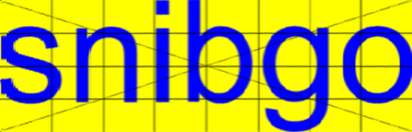
%IMG7%magick ^
  -size 600x240 ^
  -background yellow -fill Blue ^
  label:snibgo -trim +repage ^
  cp_plane.png

FOR /F "usebackq" %%L ^
IN (`%IMG7%magick identify ^
-format "WW=%%w\nHH=%%h\ncylWW=%%[fx:int(w*2/pi+0.5)]\nWW_2=%%[fx:int(w/2+0.5)]" ^
cp_plane.png`) ^
DO set %%L

call %PICTBAT%grid %WW% %HH% 8 4 1 Black None

%IMG7%magick cp_plane.png grid.png -composite cp_plane.png

del grid.png
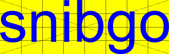
We find the dimensions of the plane, and easily calculate those of the cylinder.
An input parameter is the tilt angle, or the required dip in the centre of the cylinder.
The script does the following:
set pcDebug=1
set pcStartAng=-60
set pcEndAng=30
set pcStartAng=-90
set pcEndAng=0
set pcBackCol=Khaki
set cp_TiltAng=45
set cp_TiltAng=20

timec call %PICTBAT%plane2cyl cp_plane.png %cp_TiltAng% 2>&1>p2c.lis
rem @p2c.lis
The horizontal and vertical displacements both vary across the image, but each line has the same displacements. Hence the displacement maps can be represented by an image with a single row. We show the graphs of those single-row maps.
Horizontal displacement, cp_asin:

Vertical displacement, cp_v:

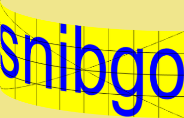
Combined map, cp_map_p2c.png (red is horizontal displacement, green is vertical, blue is irrelevant):
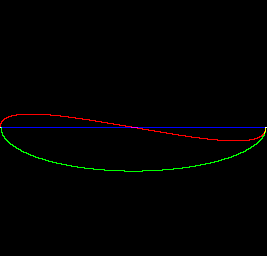
The result, cp_plane_p2c.png, is:
We assume the image is the smallest size that contains the image of the cylinder. Hence we know the width (cylinder diameter) and extended height. An input parameter is the tilt angle, or the measured dip in the centre of the cylinder, so we then calculate the cylinder height. From the cylinder width and height we calculate the plane width and height.
The script does the following:
timec call %PICTBAT%cyl2plane cp_plane_p2c.png %cp_TiltAng% 2>&1>c2p.lis
 C:\prose\pictures>rem Transforms from cylinder to plane.

C:\prose\pictures>rem cp_plane_p2c.png is image.

C:\prose\pictures>rem 20 is tilt angle, degrees. Default=0=no tilt. Positive is with camera above cylinder, looking down.
C:\pictures\planeCylSetup: Files: C:\Users\Alan\AppData\Local\Temp\p2c_h_20_-90_0.miff C:\Users\Alan\AppData\Local\Temp\p2c_v_20_-90_0.miff C:\Users\Alan\AppData\Local\Temp\p2c_c_20_-90_0.miff
C:\pictures\cyl2plane: farZAng=-90
C:\pictures\cyl2plane: extendV=239
C:\pictures\cyl2plane: extendV=239 cylWW=371 cylHH=176 plWW=582.765437 plHH=187 cylWW_2=186
C:\pictures\graph1d: WW=371 HH=1 newH=256 OUTFILE=C:\prose\pictures\cp_sinus_g1d.png
C:\pictures\graph1d: WW=371 HH=1 newH=256 OUTFILE=C:\prose\pictures\cp_v_c2p_g1d.png

TimeC call C:\pictures\cyl2plane cp_plane_p2c.png 20
Seconds: 0.50
Horizontal displacement, cp_sinus.png:

The vertical displacement is the same as for the plane-to-cylinder transformation, but in the opposite direction. cp_v_c2p.png:

The result, cp_plane_p2c_c2p.png, is:
How different is this from the original?
%IMG7%magick compare -metric RMSE cp_plane.png cp_plane_p2c_c2p.png NULL:
echo.
%IMG7%magick identify cp_plane.png
%IMG7%magick identify cp_plane_p2c_c2p.png
9618.85 (0.146774)cp_plane.png PNG 582x187 582x187+0+0 8-bit sRGB 20523B 0.000u 0:00.000
cp_plane_p2c_c2p.png PNG 583x187 583x187+0+0 8-bit sRGB 62291B 0.000u 0:00.000
For animation, we want to slowly roll a plane into a cylinder. So we need to specify small angles without needing to create large files.
To do this: "+level" the gradients that are the foundations of the displacement maps, and adjust the extendV calculations, and plWW <-> cylWW.
Hmm, not so easy. Maybe we need: "given a clut, find the difference between it and a straight line drawn through first and last points". See clutDiffEnds.bat
And it would be neat to easily get the reverse, ie the bit at the back. But this is fairly trivial: reverse the image left-to-right and negate the tilt.
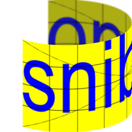
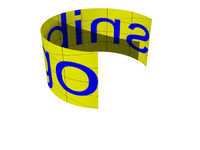
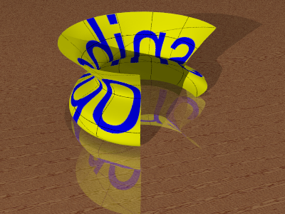
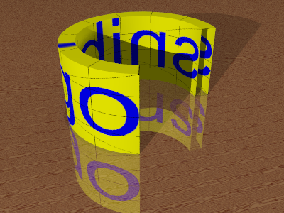
We might want to take a rectangular image and wrap it around a cylinder, in a way that facilitates animation. The script wrapCylinder.bat does the job. It takes parameters:
wrapCylinder.bat makes an appended image of two copies of the source, with a transparent gap between them and at the end. This is cropped to form the sources for the front and rear.
It calls plane2cyl.bat twice: once for the front and once for the rear. An optional effect can be applied to the rear portion, before composition.
set wcRearEffect=-modulate 75,80,100 -blur 0x1 call %PICTBAT%wrapCylinder cp_plane.png 20 -50 200 %IMG7%magick cp_plane_wc.png cp_plane_wc0.png |
|
We can animate this:
goto skipLoop set TEMPDIR=%TEMP% del /q %TEMPDIR%\snibRot_*.png set wcRearEffect=-modulate 75,80,100 -blur 0x1 set wcBackCol=White set N=0 for /L %%i in (355,-5,0) do ( set sN=00000!N! set sN=!sN:~-6! set /A endAng=%%i+250 call %PICTBAT%wrapCylinder cp_plane.png 20 %%i !endAng! copy cp_plane_wc.png %TEMPDIR%\snibRot_!sN!.png set /A N+=1 ) %IMG7%magick ^ -dispose Background ^ %TEMPDIR%\snibRot_*.png ^ -loop 0 -delay 3 -layers optimize ^ cp_snibRot.gif :skipLoop |
|
We can generalise this to a cone. For some purposes, a cone may be unrolled to a plane where the top and bottom are circular arcs. For other purposes, the narrow end can be widened to the same width as the wide end, unrolled as a cylinder, and one end narrowed again. However, tilt then probably needs to be treated separately.
From a photographed cylinder, we can derive a lighting map. Unroll the cylinder and find the difference at each pixel from the mean. For some purposes, a difference in lightness will be sufficient, or it could be a difference in each of the RGB channels.
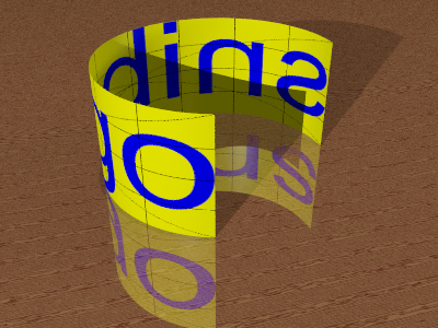
We could simulate perspective, 3-D lighting, shadows and so on. But there comes a time when it is easier to use a 3-D tool such as POV-Ray. See below for the POV-Ray scene files.
For the command-line options, see POV-Ray help, Reference, Command Line.
| -D | turn off graphic display |
| +A | anti-alias threshold |
| +W | pixels width |
| +H | pixels height |
| +FN | output bit depth |
| +UA | alpha output |
| +I | input POV script filename |
| +O | output image filename |
Examples:
|
Make a png file with transparent piece, for subsequent POV operations. %IMG7%magick ^ cp_plane.png ^ -background None -extent 144x100%% ^ cp_plane_ext.png Start with a single object. No background or sky sphere. %POV% ^ -D +A0.01 +W400 +H300 +FN16 +UA ^ +IsnibCylT.pov +Ocp_snibCylT_pov.png The shape and gradation of the shadow would be difficult using IM. |
|
|
Add a floor. %POV% ^ -D +A0.01 +W400 +H300 +FN16 ^ +IsnibCyl.pov +Ocp_snibCyl_pov.png |
|
|
A different object, using "sor" (surface of revolution). %POV% ^ -D +A0.01 +W400 +H300 +FN16 ^ +IsnibSor.pov +Ocp_snibSor_pov.png |
|
|
A different object, using "lathe". %POV% ^ -D +A0.01 +W400 +H300 +FN16 ^ +IsnibLathe.pov +Ocp_snibLathe_pov.png |
|
For a more complex example that uses POV-Ray to distort a displacement map, see my page Coffee mug.
For other uses of POV-Ray, see my page Knots: Ray-tracing.
For convenience, .bat scripts are also available in a single zip file. See Zipped BAT files.
rem Transforms from plane to cylinder.
rem %1 is image.
rem %2 is tilt angle, degrees. Default=0=no tilt. Positive is with camera above cylinder, looking down.
@rem
@rem Also uses:
@rem   pcStartAng. Default -90.
@rem   pcEndAng. Default 90.
@rem   pcDebug. Default 0.
@rem   pcBackCol. Default None.
@rem
@rem Updated:
@rem   5-August-2022 for IM v7.
@rem


@setlocal enabledelayedexpansion

@call echoOffSave

@call %PICTBAT%setInOut %1 p2c


set tiltAng=%2
if "%tiltAng%"=="" set tiltAng=0

call %PICTBAT%planeCylSetup
if ERRORLEVEL 1 exit /B 1

if %pcForceRecalc%==1 (
  del %fP2C_HORIZ%
  del %fP2C_VERT%
  del %fP2C_COMB%
)

if "%pcDebug%"=="1" echo farZAng=%farZAng%

rem plWW = width
rem plWW_2 = half width
rem cylWWxX = w*2/pi = required width of cylinder, assuming we go all the way from -90 to +90.
FOR /F "usebackq" %%L ^
IN (`%CALC% "plWW=%%w\nplWW_2=%%[fx:int(w/2+0.5)]\nplHH=%%h\ncylWWxX=%%[fx:int(w*2/pi+0.5)]" %INFILE%`) ^
DO set %%L

echo %0: plWW=%plWW%

if %ZeroAng%==1 (
  set cylRad=0
  set cylWW=%plWW%
) else (
  FOR /F "usebackq" %%L ^
IN (`%CALC% "cylRad=%%[fx:%plWW%*180/((%pcEndAng%)-(%pcStartAng%))/pi]" xc:`) ^
DO set %%L

echo %0: cylRad=%cylRad%

  FOR /F "usebackq" %%L ^
IN (`%CALC% "cylWW=%%[fx:!cylRad!*(sin(-(%pcStartAng%*pi/180))+sin(%pcEndAng%*pi/180))]\nfarZy=%%[fx:!cylRad!*abs(sin(%farZAng%*pi/180))*%sinT%]" xc:`) ^
DO set %%L
)

echo %0: cylRad=%cylRad%  cylWWxX=%cylWWxX%  cylWW=%cylWW%  farZy=%farZy%

rem cylHH = plHH * cosT
rem tiltFact = -sinT/2
FOR /F "usebackq" %%L ^
IN (`%CALC% "cylWW_2=%%[fx:int(%cylWW%/2+0.5)]\ncylHH=%%[fx:int(%plHH%*%cosT%+0.5)]\ntiltFact=%%[fx:-%sinT%/2]" xc:`) ^
DO set %%L

@rem extendV = plHH.cosT + plWW.2/pi.abs(sinT)/2
@rem FOR /F "usebackq" %%L ^
@rem IN (`%CALC% "extendV=%%[fx:int(%plHH%*%cosT%+%plWW%*2/pi*abs(%sinT%)/2+0.5)]" xc:`) ^
@rem DO set %%L

rem extendV = plHH.cosT + cylRad.abs(sinT)/2  But not /2??
FOR /F "usebackq" %%L ^
IN (`%CALC% "extraV=%%[fx:int(%cylWW%/2*abs(%sinT%)+0.5)]" xc:`) ^
DO set %%L

FOR /F "usebackq" %%L ^
IN (`%CALC% "extendV=%%[fx:int(%plHH%*%cosT%+%cylWW%/2*abs(%sinT%)+0.5)]\nIsSouth=%%[fx:%tiltAng%<0?1:0]" xc:`) ^
DO set %%L

if "%pcDebug%"=="1" echo extendV=%extendV%

if %IsSouth%==1 (
  set GRAV=South
) else (
  set GRAV=North
)

if %tiltAng%==0 (
  set EXTEND=
) else (
  set EXTEND=-gravity %GRAV% -background %pcBackCol% -extent %cylWW%x%extendV%
)

if "%pcDebug%"=="1" echo %0: plWW=%plWW% plHH=%plHH% cylWW=%cylWW% cylHH=%cylHH% plWW_2=%WW_2% cylWW_2=%cylWW_2% extendV=%extendV% tiltFact=%tiltFact%

@rem %IMG7%magick ^
@rem   -size 1x%cylWW% gradient:gray(%pc180end%%%)-gray(%pc180start%%%) -rotate 90 ^
@rem   ( +clone -function arcsin 1,0.5,1,0.5 ) ^
@rem   -evaluate Divide 2 ^
@rem   -compose ModulusSubtract -composite ^
@rem   -evaluate AddModulus 50%% ^
@rem   cp_asin.png


if exist %fP2C_COMB% goto skipComb

call %PICTBAT%p2cHoriz.bat


%IMG7%magick ^
  -size 1x%cylWW% ^
  gradient:gray(%pc180end%%%)-gray(%pc180start%%%) -rotate 90 ^
  -function Polynomial -4,4,0 -evaluate Pow 0.5 ^
  -function Polynomial %tiltFact%,0.5 ^
  %fP2C_VERT%

rem Combine the displacement maps
%IMG7%magick ^
  %fP2C_HORIZ% ^
  %fP2C_VERT% ^
  -size %cylWW%x1 xc:gray50 ^
  -combine -set colorspace sRGB ^
  %fP2C_COMB%

if "%pcDebug%"=="1" (
  %IMG7%magick %fP2C_HORIZ% cp_asin.png
  %IMG7%magick %fP2C_VERT% cp_v.png
  %IMG7%magick %fP2C_COMB% cp_map_p2c.png
  call %PICTBAT%graph1d cp_asin.png
  call %PICTBAT%graph1d cp_v.png
  call %PICTBAT%graphLineCol cp_map_p2c.png Black 0 0
)

:skipComb

if %pcBackCol%==None (
  set VIRT_PIX=-virtual-pixel None
) else (
  set VIRT_PIX=-background %pcBackCol% -virtual-pixel background
)

:: In v6, this had "-interpolate bicubic" before "-compose".
%IMG7%magick ^
  %INFILE% ^
  -resize "%cylWW%x%cylHH%^!" ^
  %EXTEND% ^
  ( %fP2C_COMB% -scale "%cylWW%x%extendV%^!" ) ^
  %VIRT_PIX% ^
  -compose displace -set option:compose:args %cylWW_2%x%cylWW_2% -composite ^
  %OUTFILE%

call echoRestore

endlocal & set p2cExtraV=%extraV%& set pcOUTFILE=%OUTFILE%
rem Transforms from cylinder to plane.
rem %1 is image.
rem %2 is tilt angle, degrees. Default=0=no tilt. Positive is with camera above cylinder, looking down.
@rem
@rem Also uses:
@rem   pcStartAng. Default -90.
@rem   pcEndAng. Default 90.
@rem   pcDebug. Default 0.
@rem   pcBackCol. Default None.
@rem
@rem Updated:
@rem   5-August-2022 for IM v7.
@rem

@setlocal enabledelayedexpansion

@call echoOffSave

call %PICTBAT%setInOut %1 c2p


set tiltAng=%2
if "%tiltAng%"=="" set tiltAng=0

call %PICTBAT%planeCylSetup
if ERRORLEVEL 1 exit /B 1

if %pcForceRecalc%==1 (
  del %fC2P_HORIZ%
  del %fC2P_VERT%
  del %fC2P_COMB%
)


if "%pcDebug%"=="1" echo %0: farZAng=%farZAng%

rem plHH=%%[fx:int((h-w*%sinT%/2)/%cosT%+0.5)]
rem tiltFact: opposite sign to Plane2Cylinder.
FOR /F "usebackq" %%L ^
IN (`%CALC% "cylWW=%%w\nextendV=%%h\ncylHH=%%[fx:int(h-w*abs(%sinT%)/2+0.5)]\nplWWxX=%%[fx:int(w*pi/2+0.5)]\ncylWW_2=%%[fx:int(w/2+0.5)]\ntiltFact=%%[fx:%sinT%/2]\nplHH=%%[fx:int((h-abs(w/2*%sinT%))/%cosT%+0.5)]" %INFILE%`) ^
DO set %%L

if "%pcDebug%"=="1" echo %0: extendV=%extendV%

if %ZeroAng%==1 (
  set cylRad=0
  set plWW=%cylWW%
) else (
  FOR /F "usebackq" %%L ^
IN (`%CALC% "cylRad=%%[fx:%cylWW%/(sin(-(%pcStartAng%*pi/180))+sin(%pcEndAng%*pi/180))]" xc:`) ^
DO set %%L

  FOR /F "usebackq" %%L ^
IN (`%CALC% "plWW=%%[fx:!cylRad!*pi*(%pcEndAng%-(%pcStartAng%))/180]\nIsSouth=%%[fx:%tiltAng%<0?1:0]" xc:`) ^
DO set %%L
)

if %IsSouth%==1 (
  set GRAV=South
) else (
  set GRAV=North
)

if "%pcDebug%"=="1" echo %0: extendV=%extendV% cylWW=%cylWW% cylHH=%cylHH% plWW=%plWW% plHH=%plHH% cylWW_2=%cylWW_2%

goto skipSelfSinus
@rem %IM%convert ^
@rem   -size 1x%cylWW% gradient:gray(%pc180end%%%)-gray(%pc180start%%%) -rotate 90 ^
@rem   ( +clone -function sinusoid 0.5,-90,0.5,0.5 ) ^
@rem   -evaluate Divide 2 ^
@rem   -compose ModulusSubtract -composite ^
@rem   -evaluate AddModulus 50%% ^
@rem   cp_sinus.png

%IMG7%magick ^
  -size 1x%cylWW% gradient:gray(%pc180end%%%)-gray(%pc180start%%%) -rotate 90 ^
  -function sinusoid 0.5,-90,0.5,0.5 ^
  cp_sinus.png

FOR /F "usebackq" %%L ^
IN (`%IMG7%magick cp_sinus.png -format "COL_0=%%[pixel:p{0,0}]\nCOL_1=%%[pixel:p{w-1,h-1}]" info:`) ^
DO set %%L

%IMG7%magick ^
  ( -size 1x%cylWW% gradient:%COL_1%-%COL_0% -rotate 90 ) ^
  cp_sinus.png ^
  -evaluate Divide 2 ^
  -compose ModulusSubtract -composite ^
  -evaluate AddModulus 50%% ^
  cp_sinus.png

:skipSelfSinus

rem Forget what we've just done. Invert the plane2cyl version.

if not exist %fC2P_HORIZ% (
  if not exist %fP2C_HORIZ% call %PICTBAT%p2cHoriz.bat

  call %PICTBAT%invRelClut %fP2C_HORIZ%
  rem %IM%convert cp_asin_irc.png cp_sinus.png
)

if "%pcDebug%"=="1" (
  %IMG7%magick %fC2P_HORIZ% cp_sinus.png
  call %PICTBAT%graph1d cp_sinus.png
)

if not exist %fC2P_VERT% %IMG7%magick ^
  -size 1x%cylWW% ^
  gradient:gray(%pc180end%%%)-gray(%pc180start%%%) -rotate 90 ^
  -function Polynomial -4,4,0 -evaluate Pow 0.5 ^
  -function Polynomial %tiltFact%,0.5 ^
  %fC2P_VERT%

if "%pcDebug%"=="1" (
  %IMG7%magick %fC2P_VERT% cp_v_c2p.png
  call %PICTBAT%graph1d cp_v_c2p.png
)


goto skipJunk

goto skipComb
rem Combine the displacement maps
%IMG7%magick ^
  %fC2P_HORIZ% ^
  %fC2P_VERT% ^
  -size %cylWW%x1 xc:gray50 ^
  -combine -set colorspace sRGB ^
  cp_map_c2p.png


:: In v6, this had "-interpolate bicubic" before "-compose".
%IMG7%magick ^
  %INFILE% ^
  ( cp_map_c2p.png -scale "%cylWW%x%extendV%^!" ) ^
  -background lightgreen -virtual-pixel background ^
  -compose displace -set option:compose:args %cylWW%x%cylWW_2% -composite ^
  %OUTFILE%
:skipComb

:: In v6, this had "-interpolate bicubic" before "-compose".
%IMG7%magick ^
  %INFILE% ^
  ( cp_v_c2p.png -scale "%cylWW%x%extendV%^!" ) ^
  -background lightgreen -virtual-pixel background ^
  -compose displace -set option:compose:args 0x%cylWW_2% -composite ^
  ( %fC2P_HORIZ% -scale "%cylWW%x%extendV%^!" ) ^
  -compose displace -set option:compose:args %cylWW%x0 -composite ^
  -crop %cylWW%x%cylHH%+0+0 +repage ^
  -resize "%plWW%x%plHH%^!" ^
  %OUTFILE%

:skipJunk

if %pcBackCol%==None (
  set VIRT_PIX=-virtual-pixel None
) else (
  set VIRT_PIX=-background %pcBackCol% -virtual-pixel background
)

rem Width was cylWW
:: In v6, this had "-interpolate bicubic" before "-compose".
%IMG7%magick ^
  %INFILE% ^
  %VIRT_PIX% ^
  ( cp_v_c2p.png -scale "%cylWW%x%extendV%^!" ) ^
  -compose displace -set option:compose:args 0x%cylWW_2% -composite ^
  ( cp_sinus.png -scale "%cylWW%x%extendV%^!" ) ^
  -compose displace -set option:compose:args %cylWW_2%x0 -composite ^
  -gravity %GRAV% ^
  -crop %cylWW%x%cylHH%+0+0 +repage ^
  -resize "%plWW%x%plHH%^!" ^
  %OUTFILE%


rem First disp args: 0x%cylWW_2%

call echoRestore
rem Called by plane2cyl and cyl2plane.
@rem
@rem Updated:
@rem   5-August-2022 for IM v7.
@rem

if "%pcStartAng%"=="" set pcStartAng=-90
if "%pcEndAng%"=="" set pcEndAng=90

if "%pcBackCol%"=="" set pcBackCol=None

if "%pcForceRecalc%"=="" set pcForceRecalc=0


set PCDIR=%TEMP%

rem FIXME: suffix also needs file dims.
rem
set SUFF=%tiltAng%_%pcStartAng%_%pcEndAng%
set fP2C_HORIZ=%PCDIR%\p2c_h_%SUFF%.miff
set fP2C_VERT=%PCDIR%\p2c_v_%SUFF%.miff
set fP2C_COMB=%PCDIR%\p2c_c_%SUFF%.miff
set fC2P_HORIZ=%PCDIR%\p2c_h_%SUFF%_irc.miff
set fC2P_VERT=%PCDIR%\c2p_v_%SUFF%.miff
set fC2P_COMB=%PCDIR%\c2p_c_%SUFF%.miff

echo %0: Files: %fP2C_HORIZ% %fP2C_VERT% %fP2C_COMB%

set CALC=%IMG7%magick identify -precision 9 -format

rem Start and end, as percentages. Zero is far left; 100 is far right.
rem ZeroAng is whether the difference between start and end is effectively zero.
rem farZAng is the angle that is most towards the back; used to calc farZy, which isn't used.
rem
set pc180start=
FOR /F "usebackq" %%L ^
IN (`%CALC% ^
  "pc180start=%%[fx:(%pcStartAng%+90)/1.80]\npc180end=%%[fx:(%pcEndAng%+90)/1.80]\nZeroAng=%%[fx:abs(%pcStartAng%-(%pcEndAng%))<0.01]\nfarZAng=%%[fx:abs(%pcStartAng%)>abs(%pcEndAng%)?%pcStartAng%:%pcEndAng%]" ^
  xc:`) ^
DO set %%L

if "%pc180start%"=="" exit /B 1

set sinT=
FOR /F "usebackq" %%L ^
IN (`%CALC% "sinT=%%[fx:sin(%tiltAng%*pi/180)]\ncosT=%%[fx:cos(%tiltAng%*pi/180)]" xc:`) ^
DO set %%L

if "%sinT%"=="" exit /B 1
rem Called by plane2cy and cyl2plane.
@rem
@rem Updated:
@rem   5-August-2022 for IM v7.
@rem

%IMG7%magick ^
  -size 1x%cylWW% gradient:gray(%pc180end%%%)-gray(%pc180start%%%) -rotate 90 ^
  -function arcsin 1,0.5,1,0.5 ^
  -depth 16 ^
  %fP2C_HORIZ%


rem FIXME: don't bother with next two if doing from -90 to +90.

FOR /F "usebackq" %%L ^
IN (`%IMG7%magick %fP2C_HORIZ% -format "COL_0=%%[pixel:p{0,0}]\nCOL_1=%%[pixel:p{w-1,h-1}]" info:`) ^
DO set %%L

%IMG7%magick ^
  ( -size 1x%cylWW% gradient:%COL_1%-%COL_0% -rotate 90 ) ^
  %fP2C_HORIZ% ^
  -compose Mathematics -define compose:args=0,0.5,-0.5,0.5 -composite ^
  %fP2C_HORIZ%
rem From image %1, wraps it into a cylinder.
rem
rem %2 is tilt angle, degrees. Default=0=no tilt. Positive is with camera above cylinder, looking down.
rem %3 is start angle, degrees. Default = -90.
rem %4 is end angle, degrees. Default = 90.
@rem
@rem Updated:
@rem   5-August-2022 for IM v7.
@rem


@if "%1"=="" findstr /B "rem @rem" %~f0 & exit /B 1

@setlocal

@call echoOffSave

call %PICTBAT%setInOut %1 wc

set CALC=%IMG7%magick identify -precision 9 -format

set tiltAng=%2
if "%tiltAng%"=="" set tiltAng=0

set startAng=%3
if "%startAng%"=="" set startAng=-90

set endAng=%4
if "%endAng%"=="" set endAng=90

if "%wcBackCol%"=="" set wcBackCol=None

rem for /F "usebackq" %%L ^
rem in (`%CALC% "ANG=%startAng%;startAng=%%[fx:while(ANG>180,ANG-=360)]" xc:`) ^
rem do set %%L

for /F "usebackq" %%L ^
in (`%CALC% "startAng=%%[fx:%startAng%<=180?%startAng%:%startAng%-360]" xc:`) ^
do set %%L

echo %0: startAng=%startAng%


rem transAng = (startAng - endAng) mod 360.

for /F "usebackq" %%L ^
in (`%CALC% "negTiltAng=%%[fx:-%tiltAng%]\ntransAng=%%[fx:ta=(%startAng%-(%endAng%))%% 360;ta<0?ta+360:ta]" xc:`) ^
do set %%L

for /F "usebackq" %%L ^
in (`%CALC% "imgAng=%%[fx:360-(%transAng%)]\nbadAng=%%[fx:%transAng%<360?0:1]" xc:`) ^
do set %%L

if %badAng%==1 (
  echo %0: Bad angle
  exit /B 1
)

echo %0: imgAng=%imgAng% transAng=%transAng%

FOR /F "usebackq" %%L ^
IN (`%CALC% "WW=%%w\nHH=%%h\ntransPix=%%[fx:w*(%transAng%)/(%imgAng%)]" %INFILE%`) ^
DO set %%L

rem So we have pix/degree = (WW + transPix) / 360

FOR /F "usebackq" %%L ^
IN (`%CALC% ^
  "pixPerDeg=%%[fx:(%WW%+w*(%transAng%)/(%imgAng%))/360]\npix360=%%[fx:%WW%+(%transPix%)]\npix180=%%[fx:(%WW%+(%transPix%))/2]" ^
  %INFILE%`) ^
DO set %%L

rem In the appended image, what are the pixel coords of -90 and +90?
rem Image starts (pix=0) at startAng and ends (pix=WW) at endAng.
rem -90 is at (-90-startAng)*pixPerDegree ??
rem +90 is at ( 90-startAng)*pixPerDegree ??

FOR /F "usebackq" %%L ^
IN (`%CALC% "pm90=%%[fx:(-90-(%startAng%))*%pixPerDeg%]" xc:`) ^
DO set %%L

FOR /F "usebackq" %%L ^
IN (`%CALC% "pp90=%%[fx:(90-(%startAng%))*%pixPerDeg%]\npmNeg=%%[fx:%pm90%<0?1:0]" xc:`) ^
DO set %%L

FOR /F "usebackq" %%L ^
IN (`%CALC% "ppNeg=%%[fx:%pp90%<0?1:0]" xc:`) ^
DO set %%L

set pixFL=%pm90%
set pixFR=%pp90%
set pixRR=%pp90%

if %pmNeg%==1 FOR /F "usebackq" %%L ^
IN (`%CALC% "pixFL=%%[fx:%pm90%+(%pix360%)]\npixFR=%%[fx:%pp90%+(%pix360%)]" xc:`) ^
DO set %%L

if %ppNeg%==1 FOR /F "usebackq" %%L ^
IN (`%CALC% "pixRR=%%[fx:%pp90%+(%pix360%)]" xc:`) ^
DO set %%L

FOR /F "usebackq" %%L ^
IN (`%CALC% "pixRL=%%[fx:%pixRR%+(%pix360%)/2]" xc:`) ^
DO set %%L

rem ccalc = %pix360% * 2 = exit

%IMG7%magick ^
  %INFILE% ^
  -size %transPix%x%HH% xc:None ^
  +append +repage ^
  ( +clone ) ^
  +append +repage ^
  -write wc_img.png ^
  ( +clone -crop %pix180%x%HH%+%pixFL%+0 +repage -write wc_front.png +delete ) ^
  ( +clone -crop %pix180%x%HH%+%pixRR%+0 +repage -flop -write wc_rear.png +delete ) ^
  NULL:

if ERRORLEVEL 1 (
  echo %0 failed
  exit /B 1
)


rem Verify:
if "%wcDEBUG%"=="1" %IMG7%magick ^
  wc_front.png ^
  wc_rear.png ^
  -append +repage ^
  -bordercolor black -border 1 ^
  wc_comp.png

set pcStartAng=-90
set pcEndAng=90
rem set pcForceRecalc=1
set pcBackCol=None
call %PICTBAT%plane2cyl wc_rear.png %negTiltAng%
call %PICTBAT%plane2cyl wc_front.png %tiltAng%

%IMG7%magick ^
  wc_rear_p2c.png ^
  %wcRearEffect% ^
  ( wc_front_p2c.png -repage +0+%p2cExtraV% ) ^
  -background %wcBackCol% ^
  -layers merge ^
  +repage ^
  %OUTFILE%
rem Makes a grid with specified number of intervals.
rem %1,%2 are width and height.
rem %3 and %4 are number of gaps between horizontal and vertical grid lines, >=1 (default 4)
rem %5 is whether to draw diagonal (default 0)
rem %6 is grid colour (default white)
rem %7 is background colour, can be "none" (default black)
rem %8 is colour for boundary
rem %9 is output file (default grid.png)
@rem
@rem Also uses:
@rem   gridSTROKE_WIDTH default 1
@rem
@rem
@rem Updated:
@rem   5-August-2022 for IM v7.
@rem

rem No required arguments.
rem @if "%2"=="" findstr /B "rem @rem" %~f0 & exit /B 1

@setlocal enabledelayedexpansion

@call echoOffSave

set WW=%1
if "%WW%"=="." set WW=
if "%WW%"=="" set WW=150
set HH=%2
if "%HH%"=="." set HH=
if "%HH%"=="" set HH=100

set nX=%3
if "%nX%"=="." set nX=
if "%nX%"=="" set nX=4
set nY=%4
if "%nY%"=="." set nY=
if "%nY%"=="" set nY=4

set DO_DIAG=%5
if "%DO_DIAG%"=="." set DO_DIAG=
if "%DO_DIAG%"=="" set DO_DIAG=0

set GRID_COL=%6
if "%GRID_COL%"=="." set GRID_COL=
if "%GRID_COL%"=="" set GRID_COL=White

set BACK_COL=%7
if "%BACK_COL%"=="." set BACK_COL=
if "%BACK_COL%"=="" set BACK_COL=Black

set BOUND_COL=%8
if "%BOUND_COL%"=="." set BOUND_COL=

set OUTFILE=%9
if "%OUTFILE%"=="." set OUTFILE=
if "%OUTFILE%"=="" set OUTFILE=grid.png

if "%gridSTROKE_WIDTH%"=="" set gridSTROKE_WIDTH=0


FOR /F "usebackq" %%L ^
IN (`%IMG7%magick identify ^
  -format ^
Wm1^=%%[fx:%WW%-1]\n^
Hm1^=%%[fx:%HH%-1]\n^
dX^=%%[fx:%WW%/%nX%]\n^
dY^=%%[fx:%HH%/%nY%]\n^
nXm1^=%%[fx:%nX%-1]\n^
nYm1^=%%[fx:%nY%-1] ^
  xc:`) ^
DO set %%L

set LINESFILE=%TEMP%\gridlines.txt
del %LINESFILE% 2>nul

if %nXm1% GTR 0 for /L %%i in (1, 1, %nXm1%) do (
  FOR /F %%L IN ('%IMG7%magick identify ^
    -format "v=%%[fx:int(%dX%*%%i+0.5)]" xc:') DO @set %%L
  echo line !v!,0 !v!,%Hm1% >>%LINESFILE%
)

if %nYm1% GTR 0 for /L %%i in (1, 1, %nYm1%) do (
  FOR /F %%L IN ('%IMG7%magick identify ^
    -format "v=%%[fx:int(%dY%*%%i+0.5)]" xc:') DO @set %%L
  echo line 0,!v! %Wm1%,!v! >>%LINESFILE%
)

if %DO_DIAG%==1 (
  echo line %Wm1%,0 0,%Hm1% >>%LINESFILE%
  echo line 0,0 %Wm1%,%Hm1% >>%LINESFILE%
)

if not "%BOUND_COL%"=="" (
  echo fill %BOUND_COL% >>%LINESFILE%
  echo line 0,0 %Wm1%,0 >>%LINESFILE%
  echo line 0,0 0,%Hm1% >>%LINESFILE%
  echo line %Wm1%,0 %Wm1%,%Hm1% >>%LINESFILE%
  echo line 0,%Hm1% %Wm1%,%Hm1% >>%LINESFILE%
)

if %gridSTROKE_WIDTH%==1 (
  set sSTROKEW=
) else (
  set sSTROKEW=-strokewidth %gridSTROKE_WIDTH%
)


%IMG7%magick ^
  -size %WW%x%HH% ^
  xc:%BACK_COL% ^
  -fill None ^
  -stroke %GRID_COL% ^
  %sSTROKEW% ^
  -draw "@%LINESFILE%" ^
  %OUTFILE%

call echoRestore
#include "cylPov.inc"

object { SnibCyl }
#include "cylPov.inc"

union {
  object { Floor }
  object { SnibCyl }
}
#include "cylPov.inc"

union {
  object { Floor }
  object { SnibSor }
}
#include "cylPov.inc"

union {
  object { Floor }
  object { SnibLathe }
}
#version 3.7;
global_settings { assumed_gamma 1.0 }

#include "colors.inc"
#include "textures.inc"
#include "shapes.inc"
#include "metals.inc"
#include "glass.inc"
#include "woods.inc"

camera {
   location <-5, 10, -15>
   angle 45 // direction <0, 0,  1.7>
   right x*image_width/image_height
   look_at <0,0,0>
}

// Uncomment the area lights only if you've got lots of time.
#declare Dist=80.0;

light_source {< -50, 25, -50> color White
     fade_distance Dist fade_power 2
//   area_light <-40, 0, -40>, <40, 0, 40>, 3, 3
//   adaptive 1
//   jitter
}
light_source {< 50, 10,  -4> color Gray30
     fade_distance Dist fade_power 2
     area_light <-20, 0, -20>, <20, 0, 20>, 3, 3
     adaptive 1
     jitter
}
light_source {< 0, 100,  0> color Gray30
     fade_distance Dist fade_power 2
//   area_light <-30, 0, -30>, <30, 0, 30>, 3, 3
//   adaptive 1
//   jitter
}

//sky_sphere {
//    pigment {
//        gradient y
//        color_map {
//            [0, 1  color Gray50 color Gray80]
//        }
//    }
//}

#declare M_Wood18B =
colour_map {
    [0.00 0.25   color rgbf < 0.50, 0.26, 0.12, 0.10>
                 color rgbf < 0.54, 0.29, 0.13, 0.20>]
    [0.25 0.40   color rgbf < 0.54, 0.29, 0.13, 0.20>
                 color rgbf < 0.55, 0.28, 0.10, 0.70>]
    [0.40 0.50   color rgbf < 0.55, 0.28, 0.10, 0.70>
                 color rgbf < 0.50, 0.23, 0.15, 0.95>]
    [0.50 0.70   color rgbf < 0.50, 0.23, 0.15, 0.95>
                 color rgbf < 0.56, 0.29, 0.17, 0.70>]
    [0.70 0.98   color rgbf < 0.56, 0.29, 0.17, 0.70>
                 color rgbf < 0.54, 0.29, 0.13, 0.20>]
    [0.98 1.00   color rgbf < 0.54, 0.29, 0.13, 0.20>
                 color rgbf < 0.50, 0.26, 0.12, 0.10>]
}


#declare Floor_Texture =
    texture { pigment { P_WoodGrain18A color_map { M_Wood18A }}}
    texture { pigment { P_WoodGrain12A color_map { M_Wood18B }}}
    texture {
        pigment { P_WoodGrain12B color_map { M_Wood18B }}
        finish { reflection 0.25 }
    }

#declare Floor =
plane { y,0
    texture { Floor_Texture
        scale 0.5
        rotate y*90
        rotate <10, 0, 15>
        translate z*4
    }
}


#declare SnibCylPig =
  pigment {
    image_map {
      "cp_plane_ext.png"
      map_type 2
    }
  }


#declare SnibCyl =
cylinder {
  <0, 0.00,  0.0>,
  <0, 1.00,  0.0>, 1
  open
  pigment { SnibCylPig }
  finish { phong 1 }
  scale 4.0
}


#declare SnibSor =
sor{
  7,
  <0.000, 0.000>,
  <0.800, 0.000>,
  <0.900, 0.300>,
  <0.600, 0.500>,
  <0.800, 0.800>,
  <1.000, 1.000>,
  <1.200, 1.200>
  open
  pigment { SnibCylPig }
  scale 4.0  rotate<0,0,0> translate<0,0,0>
}


#declare SnibLathe =
lathe {
  linear_spline
  5,
  <0.8, 0>, <1, 0>, <1, 1>, <0.8, 1>, <0.8, 0>
  pigment { SnibCylPig }
  scale 4.0  rotate<0,0,0> translate<0,0,0>
}
All images on this page were created by the commands shown, using:
%IMG7%magick -version
Version: ImageMagick 7.1.0-49 Q16-HDRI x64 7a3f3f1:20220924 https://imagemagick.org
Copyright: (C) 1999 ImageMagick Studio LLC
License: https://imagemagick.org/script/license.php
Features: Cipher DPC HDRI OpenCL
Delegates (built-in): bzlib cairo freetype gslib heic jng jp2 jpeg jxl lcms lqr lzma openexr pangocairo png ps raqm raw rsvg tiff webp xml zip zlib
Compiler: Visual Studio 2022 (193331630)
... and POV-Ray 3.7, with "Render, On completion, Exit POV-Ray for Windows" ticked.
"POV-Ray" is a trademark of Persistence of Vision Raytracer Pty Ltd.
Source file for this web page is clinder.h1. To re-create this web page, run "procH1 cylinder".
This page, including the images, is my copyright. Anyone is permitted to use or adapt any of the code, scripts or images for any purpose, including commercial use.
Anyone is permitted to re-publish this page, but only for non-commercial use.
Anyone is permitted to link to this page, including for commercial use.
Page version v2.1 27-Dec-2013.
Page created 18-Mar-2023 17:25:27.
Copyright © 2023 Alan Gibson.