%IMG7%magick toes.png -crop 267x232+0+0 +repage x.png

call %PICTBAT%gridOver x.png wrp_src.png 8 8

call %PICTBAT%gridOver toes.png wrp_src.png 8 8
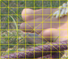
Make an image that, when physically printed and bent into a cylinder, looks like a reference image.
This page is a response to a query on an ImageMagick forum: Stretch the top and bottom of an image.
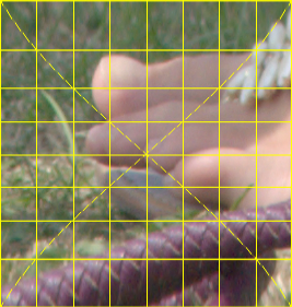
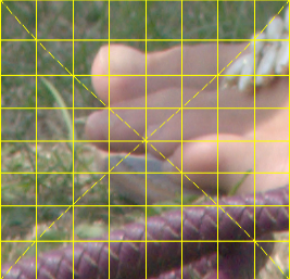
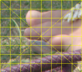
The problem is to create an image that, when printed on paper and wrapped on the surface of a horizontal cylindrical pipe, would then, from a distance, look like a reference image. The output will have the same width as the input reference, but will be taller, with most stretch at the top and bottom, and zero stretch at the centre.
This is the opposite of a more common problem, which is to make an image of what a cylinder (such as a coffee mug) would look like if a reference image were wrapped around it.
Methods on this page could be used to distort an image so that, when the distorted image is printed on a coffee mug that is viewed from the correct distance, it looks like the original undistorted image. A coffee mug has a vertical axis, so this would need the input and output to be rotated.
This page gives two methods:
%IMG7%magick toes.png -crop 267x232+0+0 +repage x.png call %PICTBAT%gridOver x.png wrp_src.png 8 8 call %PICTBAT%gridOver toes.png wrp_src.png 8 8 |
|
The script applies a 3-channel distortion map to an extended version of the input image. How do we calculate the distortion map? First, some assumptions:
Under these assumptions, there will be no horizontal distortion. There will be vertical distortion, with greatest stretching at the top and bottom, with no distortion at the centre.
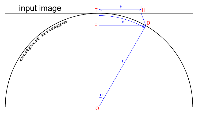
To illustrate the maths, here is a diagram of a cross-section through the pipe, showing one column of the input image and one column of the output image:
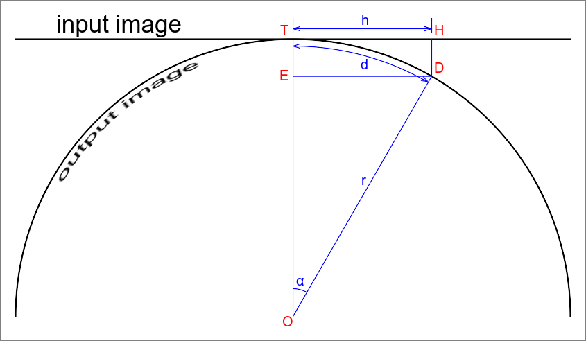
The pipe, and the output image, are shown as a circle centre O with radius r. We are concerned only with the top half. Suppose we are not given the value of r, but are given the angle α at the top (or bottom) of the image. We will see that if we are given one of these, we can calculate the other.
The centres of the input and output images are at point T.
H is some point on the input image, at distance h from T.
The projection of input point H is where the perpendicular of the input image meets the circle, at point D, at distance along the circle of d from T. Output D corresponds to input H. The angle TOD is α (alpha), in radians. Line DE is drawn parallel to HT, so they have the same lengths.
From trigonometry of triangle OED and sector OTD:
h/r = sin(α)
d = α * r
At each location in the output image, we know d, and r is a constant, so we can calculate:
α = d / r
h = r * sin(α)
  = r * sin(d / r)
This is the required transformation. The output at distance d comes from input distance h=r*sin(d/r). We will see, a couple of paragraphs down, how r is calculated. The distances are in pixels from the centres of the images. As IM numbers rows from zero at the top, and "-fx" should have its output normalised to [0..1], we need some extra juggling to create the 1xN absolute displacement map for each column of the output image.
We need to extend the input image because the output image and the displacement map will be taller than the input. We use "-extent" rather than "-resize" because we want no distortion at the centre. What is the new height?
We know the height of the input image, and half of this is hmax which is the maximum value of h. We are given alphaMax, the angle at the centre of the pipe for the top (or bottom) of the image, hence we can calculate:
r = hmax / sin(alphaMax)
dmax = alphaMax * r
dmax = alphaMax * hmax / sin(alphaMax)
dmax is half the required height of the output.
When alphaMax is very close to zero, alphaMax=sin(alphaMax), so dmax=hmax, so there is no distortion.
The inputs to the script are the input image and the value of alphaMax. Instead of alphaMax, from which the script calculates r, the script could take r as an input from which to calculate alphaMax.
All distances must be in the same units. Mathematically, it doesn't matter what the units are: inches, metres, miles, or pixels. In the scripts, all distances are in pixels.
Mathematically, dmax is a floating-point number, and the calculation is simple. But images have heights in integers. A simple implementation of the maths in ImageMagick can cause obvious asymmetry for certain image heights and certain angles. We do some fiddling to reduce this problem:
One consequence of this fiddling is that odd-numbered height inputs will always have odd-numbered height outputs, and even-numbered height inputs will always have even-numbered height outputs. For animations with varying angles, this creates jerky transitions.
If an application needs the same transformation for many input files of the same size, the map can be created once, then used in a simpler command many times.
I have implemented this as a Windows BAT script wrapPipe.bat and a bash script wrapPipe.sh. They should make the same image.
For bash, the script setIm7Path.bat ensures that "magick.exe" is on the system path.
call %PICTBAT%setIm7Path
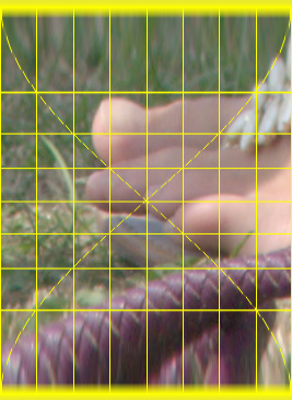
call %PICTBAT%wrapPipe.bat wrp_src.png wrp_examp1w.png 90 |
|
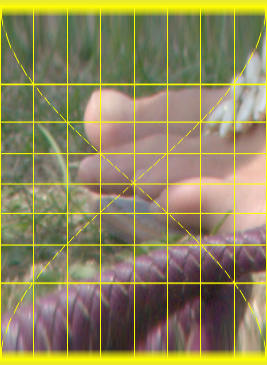
bash %PICTBAT%wrapPipe.sh wrp_src.png wrp_examp1b.png 90 |
|
%IMG7%magick compare -metric RMSE wrp_examp1w.png wrp_examp1b.png NULL:
0 (0)
The results are identical.
bash %PICTBAT%wrapPipe.sh wrp_src.png wrp_examp5.png 60 |
|
bash %PICTBAT%wrapPipe.sh wrp_src.png wrp_examp6.png 45 |
|
bash %PICTBAT%wrapPipe.sh wrp_src.png wrp_examp7.png 0.001 |
|
We can animate the effect of changing the angle. To reduce jerkiness, we operate at double size.
(Between optimizing and writing the GIF, we flatten the first frame. If we don't do this, the first frame is smaller than the page size, which messes the image-size calculation in the process that builds the web page.)
set FILES=

%IMG7%magick ^
  wrp_src.png ^
  -resize 200%% ^
  wrp_tmp.miff

for /L %%I in (1,1,90) do (
  echo %%I

  bash %PICTBAT%wrapPipe.sh wrp_tmp.miff wrp_tmp2.miff %%I

  %IMG7%magick ^
    wrp_tmp2.miff ^
    -resize 50%% ^
    wrp_frm_%%I.miff

  set FILES=!FILES! wrp_frm_%%I.miff
)

%IMG7%magick ^
  %FILES% ^
  -duplicate 10 ^
  ( +clone ^
    -set option:MYSIZE %%[fx:w]x%%[fx:h] ^
    +delete ^
  ) ^
  -gravity Center -background None -extent %%[MYSIZE] ^
  -layers optimize ^
  ( -clone 0 -background None -layers Flatten ) ^
  -swap 0,-1 +delete ^
  wrp_anim.gif

del %FILES%
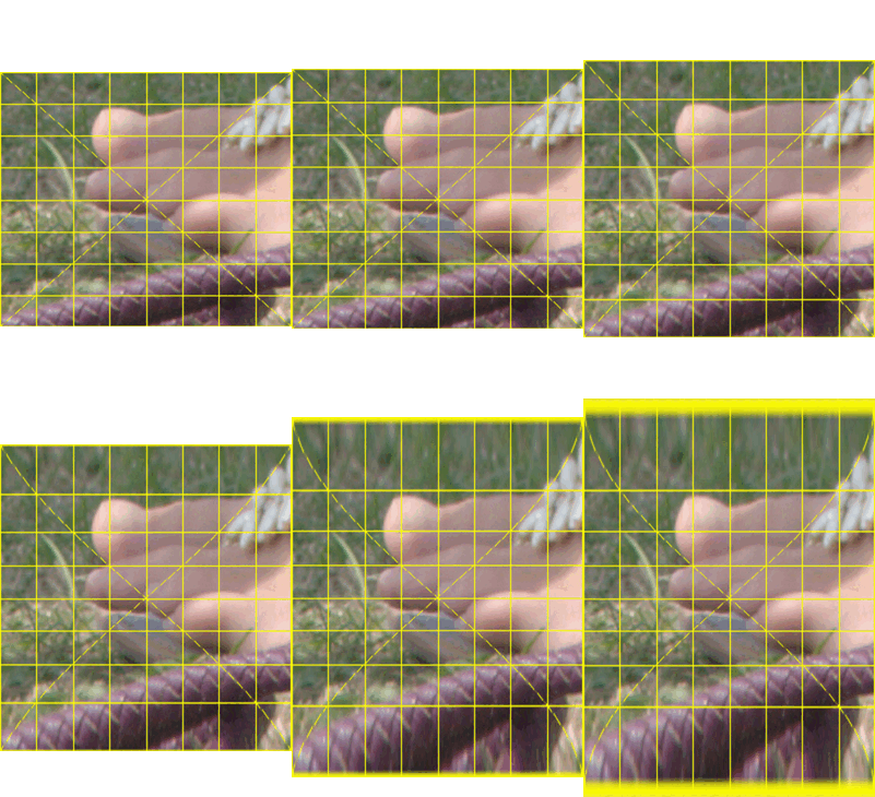
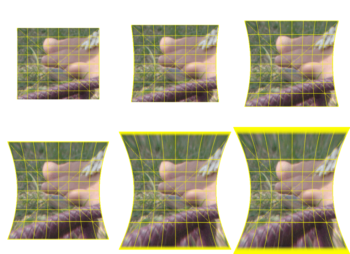
The animation shows clearly that changing the angle has greatest effect at the top and botom, and no effect in the centre.
Above, we assume orthographic projection. This is reasonable when the distance from the viewpoint (such as a human eye or camera) to the pipe is much greater than the pipe radius. One consequence of orthographic projection is that a horizontal distance at the centre of the top of the pipe appears the same size as the same horizontal distance at the edge of the pipe, despite being closer. So all the lines DH are parallel to OT, and we have only vertical distortion, with no horizontal distortion.
Instead, we can assume rectilinear projection. Then all the lines DH intersect each other at point V, at some given distance VT above point T. So line DH is not vertical, and is not the same length as line ET. The "horizon", beyond which the cylinder is hidden, is less than 180°.
We first consider the vertical distortion.
Point V is not shown on the diagram. It is the point where ET and DH, extended, intersect.
So:
ED = r * sin(α)
As in the orthographic case:
d = α * r
α = d / r
So:
ED = r * sin(d / r)
So:
h = ED * VT/VE
  = ED * VT / (VT + r - r * cos(α))
  = r * sin(d/r) * VT / (VT + r - r * cos(d/r))
How do we calculate r from alphaMax, hmax and VT? At the maximum height:
Angle VDE = VHT = atan(VT/hmax)

Angle OVD = TVH = atan(hmax/VT)
We know alphaMax so we know the angle ODE = 90°-alphaMax. Angle VDO = VDE + ODE = atan(VT/hmax) + 90°-alphaMax.
By the sine rule:
sin(OVD) = sin(VDO)
   r        r + VT
Rearrange to get an expression for r:
sin(OVD)*r + sin(OVD)*VT = sin(VDO)*r

r * (sin(VDO) - sin(OVD)) = sin(OVD)*VT

r = sin(OVD)*VT / (sin(VDO) - sin(OVD))
So, given alphaMax and hmax and VT, we can calculate r.
Alternatively, perhaps we know r (and hmax and VT) and need to calculate alphaMax. As before:
Angle VDE = VHT = atan(VT/hmax)

Angle OVD = TVH = atan(hmax/VT)
We don't know angle VDO, but we do know r, so we use the sine rule to find VDO and hence ODE.
sin(OVD) = sin(VDO)
   r        r + VT

sin(VDO) = sin(OVD) * (r+VT)
                    r
We use asin() to get VDO. But asin() returns an angle between 0 and pi/2 (0° to 90°). Unless the viewpoint is very close to the pipe, the angle should be between pi and pi/2 (180° to 90°), so we use pi-asin().
Then:
ODE = VDO - VDE
    = VDO - VHT
    = VDO - atan(VT/hmax)

alphaMax = 90° - ODE
         = 90° - (VDO - atan(VT/hmax))
         = 90° - VDO + atan(VT/hmax)
Now we know r and alphaMax, calculating dmax is simple:
dmax = r * alphaMax
Now we need an expression for h in terms of d.
Triangles VED and VTH are similar, so:
VE/VT = ED/TH

h = TH = ED * VT / VE

OE = r * cos(α)
TE = r - OE
VE = VT + TE
   = VT + r - OE
   = VT + r - r * cos(α)

h = ED * VT/VE
  = ED * VT / (VT + r - r * cos(α))
  = r * sin(d/r) * VT / (VT + r - r * cos(d/r))
This is the expression we need for the vertical displacement map. VT is a constant for the entire image. VE is a function of the distance from the centre. Note that when VT is very large, r - r * cos(d/r) is insignificant, and h = r * sin(d/r), as for the orthographic projection.
Aside: The Horizon
When V is at infinity, we have orthographic projection, and 180° of the cylinder is visible. When V is closer to the cylinder, less than 180° is visible. How much? At the horizon, angle VDO is a right-angle (90°). So:
cos(α) = OD/OV = r/(r+VT)
For example, if VT = 3*r, then cos(α) = r/(4*r) = 0.25 so α=75.52°. This is the semi-angle, so a total of 151.04° is visible.
Now we consider the horizontal distortion.
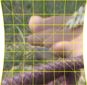
When printed and wrapped around a pipe, horizontal rows at the top and bottom are further from the viewpoint than those at the centre, by a factor of VE/VT, so they appear smaller. We need to enlarge them by a factor of VE/VT. Hence the output image will be wider at the top and bottom than at the centre. It will be stretched outwards at the top and bottom, with no stretch in the centre, an "hourglass" shape. (Recall that VT is a constant over the image, but VE is a function of the vertical distance from the centre.)
So the input image has to be extended to a new width of ww * VEmax / VT, where ww is the input width and:
VEmax = VT + r - r * cos(alphaMax)
This is implemented in wrapPipeRect.sh.
Script parameters are:
| Number | Description |
|---|---|
| 1 | Input image |
| 2 | Output image |
| 3 | Distance of viewpoint above pipe in pixels |
| 4 | Describes next parameter: either angleMax or radius. |
| 5 | Either the maximum semi-angle in degrees (0..90],
or pipe radius in pixels. |
Units of distance, including radius, are pixels. For example, if the image is to be printed at 300 dpi and wrapped around a pipe with radius 4 inches, and viewed from a height of 10 inches, then radius will be 1200 and viewpoint distance will be 3000.
For the green channel, which controls displacement in the x-direction, the value at every pixel is different. The script could use -fx for every pixel, but that would be massively slow. Instead, we calculate the green channel for just the first and last columns, then interpolate linearly between them with "-morph" and "append", with some juggling so IM works with Nx1 rather than 1xN images for performance.
The script checks for some error conditions:
The script echos and returns isBad as 0 (no error) or 1 (error).
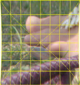
bash %PICTBAT%wrapPipeRect.sh ^ wrp_src.png wrp_rex1.png 2000 angleMax 60 |
|
|
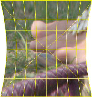
A closer viewpoint: bash %PICTBAT%wrapPipeRect.sh ^ wrp_src.png wrp_rex2.png 500 angleMax 60 |
|
|
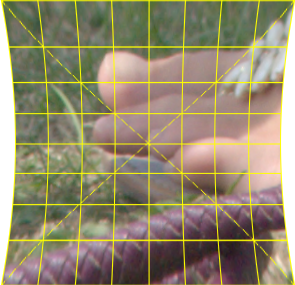
A smaller angle: bash %PICTBAT%wrapPipeRect.sh ^ wrp_src.png wrp_rex3.png 500 angleMax 45 |
|
|
Specifying the radius instead of the angle: bash %PICTBAT%wrapPipeRect.sh ^ wrp_src.png wrp_rex4.png 500 radius 180 |
|
As before, we can animate the effect of changing the angle.
set FILES=

%IMG7%magick ^
  wrp_src.png ^
  -resize 200%% ^
  wrp_tmp_r.miff

for /L %%I in (1,1,65) do (
  echo %%I

  bash %PICTBAT%wrapPipeRect.sh wrp_tmp_r.miff wrp_tmp_r2.miff 500 angleMax %%I

  %IMG7%magick ^
    wrp_tmp_r2.miff ^
    -resize 50%% ^
    wrp_frm_%%I.miff

  set FILES=!FILES! wrp_frm_%%I.miff
)

%IMG7%magick ^
  %FILES% ^
  -duplicate 10 ^
  ( +clone ^
    -set option:MYSIZE %%[fx:w]x%%[fx:h] ^
    +delete ^
  ) ^
  -gravity Center -background None -extent %%[MYSIZE] ^
  -layers optimize ^
  ( -clone 0 -background None -layers Flatten ) ^
  -swap 0,-1 +delete ^
  wrp_anim_r.gif

del %FILES%
For convenience, .bat scripts are also available in a single zip file. See Zipped BAT files.
@for %%I in (magick.exe) do @set IPATH=%%~$PATH:I

@if not "%IPATH%"=="" exit /B 0

set PATH=%IMG7%;%PATH%
rem Distort the input so that,
rem when printed and wrapped around a pipe,
rem that would look like the input image.

rem $1 is input file
rem $2 is output file
rem $3 is half the angle of the pipe we can see, in degrees, more than 0, less than or equal to 90.
rem   The script does NOT test for valid angles.

rem See also wrapPipe.sh.

@if "%1"=="" findstr /B "rem @rem" %~f0 & exit /B 1

@setlocal enabledelayedexpansion

rem @call echoOffSave

call %PICTBAT%setInOut %1 wp

if not "%2"=="" if not "%2"=="."  set OUTFILE=%2

set amaxDeg=%3

if "%amaxDeg%"=="." set amaxDeg=
if "%amaxDeg%"=="" set amaxDeg=45
if "%amaxDeg%"=="0" set amaxDeg=0.0001

set ww=%%[w]
set hh=%%[h]
set hmax=%%[fx:h/2]
set halfh=%%[fx:int(h/2)]
set amax=%%[fx:%amaxDeg%*pi/180]

for /F "usebackq" %%L in (`%IMG7%magick ^
  %INFILE% ^
  -precision 15 ^
  -format "ww=%ww%\nhh=%hh%\nhmax=%hmax%\nhalfh=%halfh%\namax=%amax%\n" ^
  info:`) do set %%L

for /F "usebackq" %%L in (`%IMG7%magick ^
  xc: ^
  -precision 15 ^
  -format "rr=%%[fx:%hmax% / sin(%amax%)]\n" ^
  info:`) do set %%L

for /F "usebackq" %%L in (`%IMG7%magick ^
  xc: ^
  -precision 15 ^
  -format "ex=%%[fx:int((%rr% * (%amax%) * 2 - %hh%) / 2)]\n" ^
  info:`) do set %%L

for /F "usebackq" %%L in (`%IMG7%magick ^
  xc: ^
  -precision 15 ^
  -format "dx=%%[fx:%halfh% + %ex% - (%halfh%-%hh%/2)]\n" ^
  info:`) do set %%L

for /F "usebackq" %%L in (`%IMG7%magick ^
  xc: ^
  -precision 15 ^
  -format "dx2=%%[fx:%dx% * 2]\n" ^
  info:`) do set %%L

echo ww=%ww% hh=%hh% hmax=%hmax% amax=%amax% halfh=%halfh% rr=%rr% ex=%ex% dx=%dx% dx2=%dx2%

%IMG7%magick ^
  ( %INFILE% ^
    -background "#88f" ^
    -gravity Center ^
    -extent %ww%x%dx2% ^
  ) ^
  ( ^
    -size %dx2%x1 xc: ^
    -fx "(%rr%*sin((i-%dx%)/%rr%)+%dx%)/w" ^
    -rotate 90 ^
    ( -size 1x%ww% gradient:Black-White -rotate -90 ) ^
    +swap ^
    ( -size 1x1 xc:"gray(50%%)" ) ^
    -scale "%ww%x%dx2%^!" ^
    -combine ^
  ) ^
  -compose Distort -composite ^
  %OUTFILE%

call echoRestore

endlocal & set wpOUTFILE=%OUTFILE%& ^
set wpDX2=%dx2%
#! /bin/bash

# Distort the input so that,
# when printed and wrapped around a pipe,
# that would look like the input image.

# $1 is input file
# $2 is output file
# $3 is half the angle of the pipe we can see, in degrees, more than 0, less than or equal to 90.
#   The script does NOT test for valid angles.

# See also wrapPipe.bat.

# Updated:
#   25-October-2021
#   27-October-2021 Fixed (?) asymmetrical problem on certain heights and angles.

if [ $# != 3 ]; then
  echo "Usage: $0 input output angle"
  exit 1
fi

infile=$1
outfile=$2
amaxDeg=$3

MAGICK=magick.exe

ww=%[w]
hh=%[h]
hmax=%[fx:h/2]
halfh="%[fx:int(h/2)]"
amax="%[fx:$amaxDeg*pi/180]"

declare $( ${MAGICK} \
  $infile \
  -precision 15 \
  -format "ww=${ww}\nhh=${hh}\nhmax=${hmax}\nhalfh=${halfh}\namax=${amax}\n" \
  info: )

rr=$(${MAGICK} xc: -precision 15 -format "%[fx:$hmax / sin($amax)]" info: )

ex=$(${MAGICK} xc: -precision 15 -format "%[fx:int(($rr * ($amax) * 2 - $hh) / 2)]" info: )

dx=$(${MAGICK} xc: -precision 15 -format "%[fx:${halfh} + $ex - (${halfh}-${hh}/2)]" info: )

dx2=$(${MAGICK} xc: -precision 15 -format "%[fx:${dx}*2]" info: )

echo ww=$ww hh=$hh hmax=$hmax amax=$amax halfh=$halfh rr=$rr ex=$ex dx=$dx dx2=$dx2

${MAGICK} \
  \( $infile \
     -background "#88f" \
     -gravity Center \
     -extent ${ww}x${dx2} \
  \) \
  \( \
     -size ${dx2}x1 xc: \
     -fx "($rr *sin((i-${dx})/$rr)+${dx})/w" \
+write e.png \
     -rotate 90 \
     \( -size 1x$ww gradient:Black-White -rotate -90 \) \
     +swap \
     \( -size 1x1 xc:"gray(50%)" \) \
     -scale "${ww}x${dx2}!" \
     -combine \
+write mymap.miff \
  \) \
  -compose Distort -composite \
  $outfile

magick e.png -format "%[fx:minima] %[fx:maxima] %[fx:1-minima]\n" info:
#! /bin/bash

# Distort the input so that,
# when printed and wrapped around a pipe,
# that would look like the input image.

# $1 is input file
# $2 is output file
# $3 distance of viewpoint above pipe
# $4 is either "angleMax" or "radius", describing the next argument.
# $5 is either the half the angle of the pipe we can see, or the radius of the pipe (in pixels)
#   If the angle: in degrees, more than 0, less than or equal to 90.
#   The script does NOT test for valid angles.

# See also wrapPipe.sh.

if [ $# != 5 ]; then
  echo "Usage: $0 input output VT paramStr param"
  exit 1
fi

infile=$1
outfile=$2
VT=$3
paramStr=$4
paramNum=$5

MAGICK=magick.exe

isBad=0

ww=%[w]
hh=%[h]
hmax=%[fx:h/2]
halfh="%[fx:int(h/2)]"
halfw="%[fx:int(w/2)]"

declare $( ${MAGICK} \
  $infile \
  -precision 15 \
  -format "ww=${ww}\nhh=${hh}\nhmax=${hmax}\nhalfh=${halfh}\nhalfw=${halfw}\n" \
  info: )

OVD="%[fx:atan(${hmax}/${VT})]"

declare $( ${MAGICK} \
  xc: \
  -precision 15 \
  -format "OVD=${OVD}\n" \
  info: )

echo VT=$VT ww=$ww hh=$hh hmax=$hmax halfh=$halfh OVD=$OVD

if [ "${paramStr}" = "angleMax" ]; then
  echo "Param is maxAngle: ${paramNum}"
  angleMax=%[fx:${paramNum}*pi/180]

  declare $( ${MAGICK} \
    xc: \
    -precision 15 \
    -format "angleMax=${angleMax}\n" \
    info: )

  VDO="%[fx:atan(${VT}/${hmax}) + pi/2 - ${angleMax}]"

  declare $( ${MAGICK} \
    xc: \
    -precision 15 \
    -format "VDO=${VDO}\n" \
    info: )

  rr="%[fx:sin(${OVD})*${VT} / (sin(${VDO}) - sin(${OVD}))]"

  declare $( ${MAGICK} \
    xc: \
    -precision 15 \
    -format "rr=${rr}\n" \
    info: )

  echo "Calculated angleMax=${angleMax} OVD=${OVD} VDO=${VDO} rr=${rr}"

elif [ "${paramStr}" = "radius" ]; then
  echo "Param is radius: ${paramNum}"
  rr=${paramNum}

  VDO="%[fx:pi-asin(min(1,sin(${OVD})*(${rr}+${VT})/${rr}))]"

  declare $( ${MAGICK} \
    xc: \
    -precision 15 \
    -format "VDO=${VDO}\n" \
    info: )

  angleMax="%[fx:pi/2-${VDO}+atan(${VT}/${hmax})]"

  declare $( ${MAGICK} \
    xc: \
    -precision 15 \
    -format "angleMax=${angleMax}\n" \
    info: )

  echo "Calculated angleMax=${angleMax} OVD=${OVD} VDO=${VDO} rr=${rr}"

else
  echo "Unknown paramStr [${paramStr}]"
  exit 1
fi


horizonAng=$(${MAGICK} \
  xc: \
  -precision 15 \
  -format "%[fx:acos(${rr}/(${rr}+${VT}))]\n" \
  info: )

isBad=$(${MAGICK} \
  xc: \
  -precision 15 \
  -format "%[fx:${angleMax}>=${horizonAng}||${rr}<=0||${VDO}<=pi/2?1:${isBad}]\n" \
  info: )

echo isBad=$isBad

${MAGICK} \
  xc: \
  -precision 15 \
  -format "VDOdeg=%[fx:${VDO}*180/pi]\nangleMaxdeg=%[fx:${angleMax}*180/pi]\nhorizonAngdeg=%[fx:${horizonAng}*180/pi]\n" \
  info:


amax=$angleMax

ex=$(${MAGICK} xc: -precision 15 -format "%[fx:int(($rr * ($amax) * 2 - $hh) / 2)]" info: )

dx=$(${MAGICK} xc: -precision 15 -format "%[fx:${halfh} + $ex - (${halfh}-${hh}/2)]" info: )

dx2=$(${MAGICK} xc: -precision 15 -format "%[fx:${dx}*2]" info: )

echo horizonAng=$horizonAng ww=$ww hh=$hh hmax=$hmax amax=$amax halfh=$halfh rr=$rr ex=$ex dx=$dx dx2=$dx2


exh=$(${MAGICK} xc: -precision 15 -format "%[fx:int(($ww*($VT + $rr - $rr * cos($angleMax))/$VT-$ww)/2)]" info: )

wwNewHlf=$(${MAGICK} xc: -precision 15 -format "%[fx:${halfw} + $exh - (${halfw}-${ww}/2)]" info: )

wwNew=$(${MAGICK} xc: -precision 15 -format "%[fx:$wwNewHlf * 2]" info: )

echo exh=$exh wwNewHlf=$wwNewHlf wwNew=$wwNew

${MAGICK} \
  \( $infile \
     -background None \
     -gravity Center \
     -extent ${wwNew}x${dx2} \
  \) \
  \( \
     -size ${dx2}x1 xc: \
     -fx "dr=(i-${dx})/${rr}; ($rr*sin(dr)*$VT/($VT+$rr-$rr*cos(dr))+${dx})/w" \
     -rotate 90 \
     -scale "${wwNew}x${dx2}!" \
     \( -size ${dx2}x1 xc: \
        -fx "dh=(0-$wwNewHlf)/${wwNew}; al=(i-$dx)/${rr}; ${wwNew}/(${wwNew}-2) * dh * $VT/($VT + $rr - $rr * cos(al))+0.5" \
        \( xc: \
          -fx "dh=(${wwNew}-1-$wwNewHlf)/${wwNew}; al=(i-$dx)/${rr}; ${wwNew}/(${wwNew}-2) * dh * $VT/($VT + $rr - $rr * cos(al))+0.5" \
        \) \
        -morph %[fx:${wwNew}-2] \
        -reverse -append \
        -rotate 90 \
        -alpha off \
     \) \
     +swap \
     \( -size ${wwNew}x${dx2} xc:"gray(50%)" \) \
     -combine \
     -alpha off \
  \) \
  -compose Distort -composite \
  $outfile

exit $isBad
All images on this page were created by the commands shown, using:
%IMG7%magick identify -version
Version: ImageMagick 7.1.0-4 Q16 x64 2021-07-18 https://imagemagick.org
Copyright: (C) 1999-2021 ImageMagick Studio LLC
License: https://imagemagick.org/script/license.php
Visual C++: 192930038
Features: Cipher DPC HDRI Modules OpenCL OpenMP(2.0)
Delegates (built-in): bzlib cairo flif freetype gslib heic jng jp2 jpeg jxl lcms lqr lzma openexr pangocairo png ps raqm raw rsvg tiff webp xml zip zlib
To improve internet download speeds, some images may have been automatically converted (by ImageMagick, of course) from PNG or TIFF or MIFF to JPG.
Source file for this web page is wrappipe.h1. To re-create this web page, execute "procH1 wrappipe".
This page, including the images, is my copyright. Anyone is permitted to use or adapt any of the code, scripts or images for any purpose, including commercial use.
Anyone is permitted to re-publish this page, but only for non-commercial use.
Anyone is permitted to link to this page, including for commercial use.
Page version v1.0 3-November-2021.
Page created 11-Nov-2021 19:05:51.
Copyright © 2021 Alan Gibson.