snibgo's ImageMagick pages
Putting OOG back in the box
When pixels have become out of gamut, how do we put them back in?
Some operations result in colours that are out of gamut ("OOG"), that is, some pixels have values outside the range of 0 to 100% of QuantumRange. If we are using integer IM, or saving to an integer file format, then these values will be clamped (or "clipped") to 0 or 100%, and any detail in those pixels is lost, and cannot be reconstructed. We won't even know which pixels were OOG, though we might guess that any values at 0 or 100% were OOG, and we might attempt reconstruction from nearby pixels that are not at the limits.
Being out of gamut is not, of itself, a problem. We can continue processing with floating-point. But, eventually, we usually want to bring all the colours within gamut, if only because output devices can't display OOG colors.
This page isn't about recovering data that has been lost due to clipping. It is about preventing the loss in the first place.
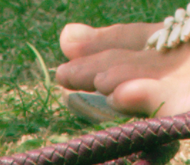
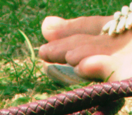
For example, from the
Colours to matrix and polynomials page, where the intention is to change toes.png to look more like toes_x_holed.png:
set SRC=ob_src.miff

set FMTrgb=^
red: %%[fx:minima.r] to %%[fx:maxima.r]\n^
green: %%[fx:minima.g] to %%[fx:maxima.g]\n^
blue: %%[fx:minima.b] to %%[fx:maxima.b]\n

%IM7DEV%magick ^
  toes.png ^
  toes_x_holed.png ^
  -process 'cols2mat weightAlpha' ^
  -depth 32 ^
  -define quantum:format=floating-point ^
  -format "%FMTrgb%" ^
  +write info: ^
  %SRC%
red: -0.46074721 to 1.7434018
green: -0.14116973 to 1.2328533
blue: -0.42654275 to 1.2380592
|

|
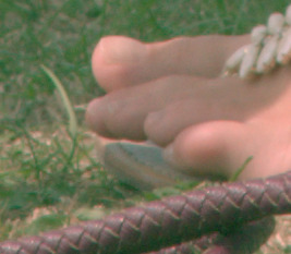
We have shown the range of values in each channel as multiples of QuantumRange, and saved the image to a floating-point miff (which you can download:
ob_src.miff). For display on the web, the image has been clamped and converted to JPEG. Notice how the skin-tone at the right-edge bleeds into the white page background.
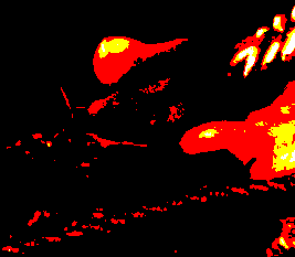
Working in floating-point, we can readily isolate pixels where a channel is more than 100%, and where a channel is less than zero.
%IM7DEV%magick ^
  %SRC% ^
  -channel RGB ^
  -threshold 100%% ^
  +channel ^
  +write ob_th3hi.png ^
  -fill White +opaque Black ^
  -format %%[fx:mean] ^
  info:
0.15635499
This proportion of pixels are >100%.
|
|
%IM7DEV%magick ^
  %SRC% ^
  -channel RGB ^
  -negate ^
  -threshold 100%% ^
  +channel ^
  +write ob_th3lo.png ^
  -fill White +opaque Black ^
  -format %%[fx:mean] ^
  info:
0.075211779
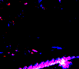
This proportion of pixels are <0%.
|
|
In the first result, most pixels are black. In those positions, pixels have not exceeded 100%. The red pixels are where only the red channel exceeded 100%. Yellow pixels are where both red and green exceeded 100%. The small number of white pixels are where all three channels exceeded 100%.
The second result works in a similar way: it is blue where the blue channel was less than zero, magenta where both red and blue were less zero, and so on.
How can we process the floating-point image to bring all pixels into gamut?
We can explicitly clamp (or "clip") the pixel values:
%IM7DEV%magick ^
  %SRC% ^
  -clamp ^
  -depth 32 ^
  -define quantum:format=floating-point ^
  -format "%FMTrgb%" ^
  +write info: ^
  ob_clmp.miff
red: 0 to 1
green: 0 to 1
blue: 0 to 1
|

|
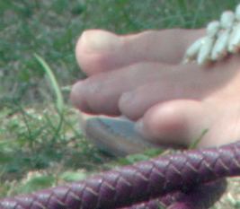
This has clamped values beyond 0 or 100% to those limits. Detail is lost, especially in parts of the sandal top-right of the image. (Many pixels that were different have become the same, pure white.)
Instead of clamping, we can "-auto-level". This applies a gain and bias that modifies all pixels, probably reducing contrast, squishing values together so they fit in the range. The same transformation is usually applied to all the channels, though they can be processed separately (but this will create a colour cast).
%IM7DEV%magick ^
  %SRC% ^
  -auto-level ^
  ob_al.jpg
|
|
%IM7DEV%magick ^
  %SRC% ^
  -channel RGB ^
  -auto-level ^
  +channel ^
  ob_al2.jpg
|
|
This has retained all the detail in all the pixels. Applying the same transformation to all channels has reduced contrast heavily. Processing the channels separately hasn't reduced contrast as much, but has created a colour cast.
For some purposes, the mean of clamped and auto-levelled versions is satisfactory, though it does lower the contrast even in the mid-tones:
%IM7DEV%magick ^
  %SRC% ^
  ( -clone 0 -clamp )^
  ( -clone 0 -auto-level )^
  -delete 0 ^
  -evaluate-sequence Mean ^
  ob_clmpal.png
|
|
Another option is to modulate all values outside certain limits, say all values above 0.9 or below 0.1. The modulation is by a linear function (the usual gain-and-bias) where a value at 0.9 is unchanged but greater values are progressively reduced so the highest value is transformed to 1.0. We modulate values below 0.1 in a similar way. The overall transformation is shown in green on this diagram:
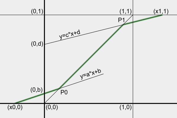
In the diagram, in-gamut colours are in the square between (0,0) and (1,1). Input values are between x0 and x1, where x0<0 and x1>1. We want the output values to be between 0 and 1. Most input values, those between P0 and P1 (where P0<P1), are unchanged. Input values between x0 and P0 will be transformed linearly by y=a*x+b, and values between P1 and x1 will be transformed by y=c*x+d, where a, b, c and d are calculated from x0, x1, P0 and P1:
a = -P0 / (x0 - P0)
b = P0 * x0 / (x0 - P0)
c = (1-P1) / (x1-P1)
d = P1 * (x1-1) / (x1-P1)
Highlights and shadows are processed independently. OOG may occur in highlights, or shadows, or both.
This will reduce contrast where the input is less than P0 or more than P1, and will cause hue-shift for RGB pixels that have channels straddling P0 or P1. Setting P0 to 0.0 will clip shadows; setting P1 to 1.0 will clip highlights.
Three methods are shown. The first operates on all colour channels (usually red, green and blue), applying the same transformation to each channel. The second operates on all colour channels, applying independent transformations to each channel. The third operates on the L channel of HCLp.
call %PICTBAT%oogLinear ^
  "%SRC%" ob_linsam.png
|

|
P0=0.1 P1=0.9
DO_LO=1 DO_HI=1
X0=-0.4607472122788306 X1=1.743401766229282
a=0.1783334768506618 b=0.08216665231493381 c=0.1185674538566411 d=0.7932892915290232
The script
oogLinear3.bat separates the image, makes three independent calls to oogLinear.bat, and combines the results.
call %PICTBAT%oogLinear3 ^
  "%SRC%" ob_linind.png
|

|
P0=0.1 P1=0.9
DO_LO=1 DO_HI=1
X0=-0.4607472122788306 X1=1.743401766229282
a=0.1783334768506618 b=0.08216665231493381 c=0.1185674538566411 d=0.7932892915290232
P0=0.1 P1=0.9
DO_LO=1 DO_HI=1
X0=-0.1411697268814709 X1=1.23285329370593
a=0.4146457405458173 b=0.05853542594541827 c=0.3004326587446907 d=0.6296106071297783
P0=0.1 P1=0.9
DO_LO=1 DO_HI=1
X0=-0.4265427590409626 X1=1.238059163381825
a=0.1899180993052465 b=0.08100819006947536 c=0.2958062103675438 d=0.6337744106692106
call %PICTBAT%oogLinear ^
  "%SRC% -colorspace HCLp -channel 2 -separate"
P0=0.1 P1=0.9
DO_LO=1 DO_HI=1
X0=-0.196691288925086 X1=1.347245902512352
a=0.3370506777003818 b=0.06629493222996184 c=0.2235906454106378 d=0.698768419130426
set FMThclp=^
H: %%[fx:minima.r] to %%[fx:maxima.r]\n^
C: %%[fx:minima.g] to %%[fx:maxima.g]\n^
L: %%[fx:minima.b] to %%[fx:maxima.b]\n

%IM7DEV%magick ^
  %SRC% ^
  -colorspace HCLp ^
  -depth 32 ^
  -define quantum:format=floating-point ^
  -format "%FMThclp%" ^
  info:
H: 5.996057e-06 to 0.99997204
C: 0.011567771 to 0.8436982
L: -0.19669129 to 1.3472459
|
[No image]
|
In HCLp colorspace, only the L (Luma) channel of this image has OOG values. (In general, the C channel may also be OOG.)
%IM7DEV%magick ^
  %SRC% ^
  -colorspace HCLp ^
  -separate ^
  -depth 32 ^
  -define quantum:format=floating-point ^
  ob_hclp.miff

call %PICTBAT%oogLinear ^
  ob_hclp.miff[2] ob_hclp_lcorr.miff
|
[No image]
|
P0=0.1 P1=0.9
DO_LO=1 DO_HI=1
X0=-0.1966912895899013 X1=1.347245931939046
a=0.3370506769451306 b=0.06629493230548694 c=0.2235906306994173 d=0.6987684323705243
%IM7DEV%magick ^
  ob_hclp.miff ^
  ob_hclp_lcorr.miff ^
  -swap 2,-1 ^
  +delete ^
  -combine ^
  -set colorspace HCLp ^
  -depth 32 ^
  -define quantum:format=floating-point ^
  -format "%FMThclp%" ^
  +write info: ^
  -colorspace sRGB ^
  -format "%FMTrgb%" ^
  +write info: ^
  ob_hclp_lin.miff
H: 5.9960571e-06 to 0.99997205
C: 0.011567771 to 0.8436982
L: 0 to 1
red: 0 to 1
green: 0 to 1
blue: 0 to 1
|

|
The script oogLinear3.bat is more convenient:
%IM7DEV%magick ^
  %SRC% ^
  -colorspace HCLp ^
  -depth 32 ^
  -define "quantum:format=floating-point" ^
  ob_src_hclp.miff

call %PICTBAT%oogLinear3 ^
  ob_src_hclp.miff ob_hclps2.miff

%IM7DEV%magick ^
  ob_hclps2.miff ^
  -colorspace sRGB ^
  -depth 32 ^
  -define "quantum:format=floating-point" ^
  ob_hclp2_lin.miff
|

|
P0=0.1 P1=0.9
DO_LO=0 DO_HI=0
X0=5.996057099341661e-06 X1=0.9999720456544244
a=1.000059964166479 b=-5.996416647907785e-06 c=1.00027962162215 d=-0.0002516594599351878
P0=0.1 P1=0.9
DO_LO=0 DO_HI=0
X0=0.01156777143747727 X1=0.8436982037601289
a=1.130809452905495 b=-0.01308094529054948 c=-1.776142266828483 d=2.498528040145635
P0=0.1 P1=0.9
DO_LO=1 DO_HI=1
X0=-0.1966912895899013 X1=1.347245931939046
a=0.3370506769451306 b=0.06629493230548694 c=0.2235906306994173 d=0.6987684323705243
Instead of a linear transformation at each end, we can use power curves (sometimes called filmic curves, as they mimic the response of photographic film). These will have slopes of zero at (x0,0) and (x1,1), and one at P0 and P1.
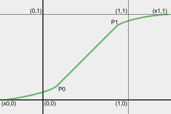
The power curve with zero gradient at the origin (0,0) is:
y = A*x^B
The gradient is:
y' = B*A*x^(B-1)
Taking logs of the curve:
ln(y) = ln(A*x^B)
      = lnA + B*ln(x)

lnA = ln(y) - B*ln(x)
Taking logs of the gradient:
ln(y') = ln(B*A*x^(B-1))
       = ln(B) + lnA + (B-1)*ln(x)
Substitute lnA:
ln(y') = ln(B) + ln(y) - B*ln(x) + (B-1)*ln(x)
       = ln(B) + ln(y) - ln(x)
y'= B*y/x
B = y'*x/y
So we can calculate B and lnA from a known gradient, at P0 or P1.
At the toe, the curve origin is at (x0,0), and the slope at P0 is one, so:
B0 = (P0-x0)/P0
lnA0 = ln(P0) - B0*ln(P0-x0)
A0 = P0/(P0-x0)^B0
... and we will use the equation y = A0*(x-x0)^B0. The gradient of the toe curve is y' = B0*A0*(x-x0)^(B0-1).
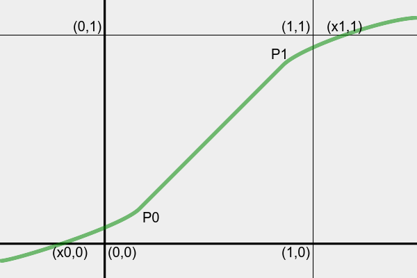
At the shoulder, the origin is at (x1,1), and the slope at P1 is one, and both axes are negated, so:
B1 = (x1-P1)/(1-P1)
A1 = (1-P1)/(x1-P1)^B1
... and we will use the equation y = 1 - A1*(x1-x)^B1. The gradient of the shoulder curve is y' = B1*A1*(x1-x)^(B1-1).
As for the linear transformation, this method can be applied to all channels together or independently, or just to a lightness channel. Here, we use only one method: all channels together. The script
oogPower.bat implements this, using "-fx". (See below
Process module below for a faster method.)
call %PICTBAT%oogPower ^
  "%SRC%" ob_powsam.png
|

|
P0=0.1 P1=0.9
DO_LO=1 DO_HI=1
X0=-0.4607472092679484 X1=1.743401784351873
A0=2.563193296178208 B0=5.607472092679484 A1=0.4205583073525658 B1=8.434017843518731
min=1.360857275178842e-08  max=1
See also
Filmic Tonemapping with Piecewise Power Curves, John Hable, 2017.
The above creates power curves that have zero gradient at y=0 (at the shadows) and y=1 (at the highlights). This compresses contrast in the shadows (which is generally okay) and in the highlights (which can look bad). It would be useful if non-zero gradients could be specified, with values between zero and one.
Considering just the shadow region, we want a power curve that passes through (x0,0) and P0, with gradient G0 at (x0,0) and 1.0 at P0.
The general equation will be:
y = A0*(x-OffsX)^B0 + OffsY
... where the gradient is zero at (OffsX,OffsY).
We need expressions for OffsX, OffsY, A0 and B0, all in terms of x0, P0 and G0.
Passing through (x0,0) and (P0,P0):
0  = A0*(x0-OffsX)^B0 + OffsY
P0 = A0*(P0-OffsX)^B0 + OffsY
Subtracting:
P0 = A0*(P0-OffsX)^B0 - A0*(x0-OffsX)^B0
P0/A0 = (P0-OffsX)^B0 - (x0-OffsX)^B0 ... but this isn't used?
Differentiating the general equation:
y' = B0*A0*(x-OffsX)^(B0-1)
At (OffsX,OffsY), y'=0, so:
0 = B0*A0*(OffsX-OffsX)^(B0-1)
  = 0 as required.
At (x0,0), y'=G0, so:
G0 = B0*A0*(x0-OffsX)^(B0-1)
At (P0,P0), y'=1, so:
1 = B0*A0*(P0-OffsX)^(B0-1)
Divide:
G0 = (x0-OffsX)^(B0-1) / (P0-OffsX)^(B0-1)
   = [ (x0-OffsX) / (P0-OffsX) ] ^ (B0-1)
... Or we do this with splines, each with two control points.
... Or we do this with cubic curves.
y = a*x^3 + b*x^2 + c*x + d

y' = 3*a*x^2 + 2*b*x + c

[[ y'' = 6*a*x + 2*b ]]
Passing through (x0,0) and (P0,P0):
0  = a*x0^3 + b*x0^2 + c*x0 + d   ... (1)
P0 = a*P0^3 + b*P0^2 + c*P0 + d   ... (2)
Subtracting (2)-(1):
P0 = a*P0^3 + b*P0^2 + c*P0 - a*x0^3 - b*x0^2 - c*x0
   = a*(P0^3-x0^3) + b*(P0^2-x0^2) + c*(P0-x0)    ... (3)
At (x0,0), y'=G0, so:
G0 = 3*a*x0^2 + 2*b*x0 + c ... (4)
At (P0,P0), y'=1, so:
1 = 3*a*P0^2 + 2*b*P0 + c   ... (5)

c = 1 - 3*a*P0^2 - 2*b*P0
Subtracting (5)-(4):
1 - G0 = 3*a*P0^2 + 2*b*P0 - 3*a*x0^2 - 2*b*x0
       = 3*a*(P0^2-x0^2) + 2*b*(P0-x0)

b = [ (1 - G0) - 3*a*(P0^2-x0^2) ] / [ 2*(P0-x0) ]
Substitute c:
G0 = 3*a*x0^2 + 2*b*x0 + c
   = 3*a*x0^2 + 2*b*x0 + 1 - 3*a*P0^2 - 2*b*P0
   = 3*a*(x0^2 - P0^2) + 2*b*(x0 - P0) + 1   This is not new.
[[ At (P0,P0), y''=0, so:
0 = 6*a*P0 + 2*b
b = -3*a*P0
]]
Substitute b:
[[
1 - G0 = 3*a*(P0^2-x0^2) -2*3*a*P0*(P0-x0)
       = a * (3*P0^2 - 3*x0^2 - 6*P0*(P0-x0) )
       = a * (3*P0^2 - 3*x0^2 - 6*P0^2 + 6*P0*x0)
       = 3*a * (P0^2 - x0^2 - 2*P0^2 + 2*P0*x0)
       = 3*a * (-P0^2 - x0^2 + 2*P0*x0)
       = -3*a * (P0^2 + x0^2 - 2*P0*x0)
       = -3*a * (P0 - x0)^2

a = (1-G0) / [ -3 * (P0 - x0)^2 ]
]]

[[
b = -3*a*P0
  = -3 * P0 * (1-G0) / [ -3 * (P0 - x0)^2 ]
  = P0 * (1-G0) / (P0 - x0)^2

c = 1 - 3*a*P0^2 - 2*b*P0

0 = a*x0^3 + b*x0^2 + c*x0 + d
d = -a*x0^3 - b*x0^2 - c*x0
]]
... Or a quadratic:
y = a*x^2 + b*x + c

y' = 2*a*x + b
At the shadows:
Passing through (x0,0) and (P0,P0):
0 = a*x0^2 + b*x0 + c
P0 = a*P0^2 + b*P0 + c
Subract:
P0 = a*(P0^2-x0^2) + b*(P0-x0)

b = [ P0 - a*(P0^2-x0^2) ] / (P0-x0)
Gradient at (x0,0) is G0, and at (P0,P0) is 1.0:
G0 = 2*a*x0 + b
1 = 2*a*P0 + b
Subtract:
1 - G0 = 2*a*(P0-x0)

a = (1-G0) / [ 2*(P0-x0) ]
At x=x0, y=0:
0 = a*x0^2 + b*x0 + c

c = -a*x0^2 - b*x0
At the highlights:
Passing through (x1,1) and (P1,P1):
1 = a*x1^2 + b*x1 + c
P1 = a*P1^2 + b*P1 + c
Subract:
P1 - 1 = a*(P1^2-x1^2) + b*(P1-x1)

b = [ P1 - 1 - a*(P1^2-x1^2) ] / (P1-x1)
Gradient at (x1,1) is G1, and at (P1,P1) is 1:
G1 = 2*a*x1 + b
1 = 2*a*P1 + b
Subtract:
1 - G1 = 2*a*(P1-x1)

a = (1-G1) / [ 2*(P1-x1) ]
b = 1 - 2*a*P1

1 = a*x1^2 + b*x1 + c
c = 1 - a*x1^2 - b*x1
... Or solve simultaneous equations by GaussJordan elimination.
... Or consider case where origin is at gradient=0, and adjust later.
y = a*x^3 + b*x^2 + c*x
y' = 3*a*x^2 + 2*b*x
Passes through (xA,yA) and (xB,yB):
yA = a*xA^3 + b*xA^2 + c*xA   ... (1)
yB = a*xB^3 + b*xB^2 + c*xB   ... (2)
At (xA,yA) gradient is GA:
GA = 3*a*xA^2 + 2*b*xA ... (3)
At (xB,yB) gradient is 1:
1 = 3*a*xB^2 + 2*b*xB   ... (4)

b = (1 - 3*a*xB^2) / (2*xB)
Cross-multiply (3) and (4):
2*xB*Ga = 2*xB*3*a*xA^2 + 2*xB*2*b*xA   ... (5)
2*xA*1  = 2*xA*3*a*xB^2 + 2*xA*2*b*xB   ... (6)
(6)-(5):
2*xA*1 - 2*xB*Ga  = 2*xA*3*a*xB^2 - 2*xB*3*a*xA^2
xA - xB*Ga  = xA*3*a*xB^2 - xB*3*a*xA^2
a = (xA - xB*Ga) / (xA*3*xB^2 - xB*3*xA^2)
  = (xA - xB*Ga) / [ 3*xA*xB * (xB-xA) ]
From (4) we know b. From (1) or (2) we know c.
However, we don't know xA, xB, yA or yB. We know only the relative values xB-xA and yB-yA.
... Or do a power curve, blended with a linear transformation.
Most of the results have differences that are subtle. For comparison purposes, we make a GIF of the results that are similar.
%IMG7%magick ^
  -loop 0 ^
  -delay 100 ^
  -gravity NorthWest -fill White ^
  ( ob_clmp.miff      -annotate +10+10 "Clamp" ) ^
  ( ob_clmpal.png     -annotate +10+10 "ClampAL" ) ^
  ( ob_linsam.png     -annotate +10+10 "LinSame" ) ^
  ( ob_linind.png     -annotate +10+10 "LinInd" ) ^
  ( ob_hclp_lin.miff  -annotate +10+10 "HCLP" ) ^
  ( ob_hclp2_lin.miff -annotate +10+10 "HCLP2" ) ^
  ( ob_powsam.png     -annotate +10+10 "PowSame" ) ^
  ob_all.gif
|

|
Which method is best?
- Applying the process in sRGB space, whether by a single transformation or three independent transformations, can change hues slightly.
- Applying the process in HCLp won't change hues.
- In this example, the linear sRGB transformations darken highlights somewhat.
- The power method preserves relative brightness very closely.
I currently have no conclusion about the "best" method.
The process module oogbox is faster, especially for the power curve, and can be incorporated into "convert" or "magick" commands.
Options are:
| Option |
Description |
Short
form |
Long form |
| m string
|
method string
|
Method for adjusting the shadows and highlights, one of:
Linear
Power
Default = Power. |
| fmn number
|
forceMin number
|
Force minimum value (override calculation).
Default: use calculated value. |
| fmx number
|
forceMax number
|
Force maximum value (override calculation).
Default: use calculated value. |
| l number
|
loLimit number
|
Low limit for shadow processing.
Default: 0.1. |
| h number
|
hiLimit number
|
High limit for highlight processing.
Default: 0.9. |
| lg number
|
loGradient number
|
Gradient for shadows.
Default: use calculated value. |
| hg number
|
hiGradient number
|
Gradient for highlights.
Default: use calculated value. |
| v
|
verbose
|
Write some text output to stderr. |
|
|
version
|
Write version information to stdout. |
The parameters loLimit and hiLimit take the place of P0 and P1 in the description above. To prevent any shadow processing, set loLimit to 0.0 or less. Likewise to prevent any highlight processing, set hiLimit to 1.0 or more.
By default, minimum and maximum statistics are taken from all channels, and all channels are adjusted, by the same amount. To use the statistics from only certain channels, and adjust only those channels, use the IM -channel setting. (Before December 2022, the module had a "channel" setting, and explicily processed red, green and blue channels. Now it uses the general IM "-channel" setting, and processes all channels that have the "update" trait.)
Hence, to adjust RGB channels independently, run the module three times with different -channel settings.
The module calculates the minimum and maximum values. To override these, use forceMin and/or forceMax. For method power, values outside the range will not be changed. For method linear and method blend, values outside the range will be changed, but not far enough to bring them inside the box.
|
All channels, same transformation
%IM7DEV%magick ^
  "%SRC%" ^
  -process 'oogbox m Linear' ^
  ob_linsamp.png
|
|
|
All channels, idenpendent transformations
%IM7DEV%magick ^
  "%SRC%" ^
  -channel 0 -process 'oogbox m Linear' ^
  -channel 1 -process 'oogbox m Linear' ^
  -channel 2 -process 'oogbox m Linear' ^
  +channel ^
  ob_linindp.png
|
|
|
Lightness only
%IM7DEV%magick ^
  "%SRC%" ^
  -colorspace HCLp ^
  -channel 2 -process 'oogbox m Linear' ^
  -colorspace sRGB ^
  -depth 32 ^
  -define "quantum:format=floating-point" ^
  ob_hclp2_linp.miff
|
|
|
Power modulation
%IM7DEV%magick ^
  "%SRC%" ^
  -process 'oogbox m Power' ^
  ob_powsamp.png
|

|
Those results from the process module should be the same as the corresponding results from the scripts:
%IMG7%magick compare -metric RMSE ob_linsamp.png ob_linsam.png NULL:
%IMG7%magick compare -metric RMSE ob_linindp.png ob_linind.png NULL:
%IMG7%magick compare -metric RMSE ob_hclp2_linp.miff ob_hclp2_lin.miff NULL:
%IMG7%magick compare -metric RMSE ob_powsamp.png ob_powsam.png NULL:
0.0376104 (5.73898e-07)0.0360092 (5.49465e-07)0.00192366 (2.93531e-08)0.0352574 (5.37993e-07)
As expected, the differences are virtually zero, which confirms the process module has the same effect as the scripts.
The process module is also useful when converting camera raw files into colorspaces. See
Squishing xyY into shape.
To see the effect more easily, we create a Nx1 gradient image with values outside 0 to 100%:
%IMG7%magick ^
  -size 600x1 gradient:Black-White ^
  -evaluate Multiply 1.6 ^
  -evaluate Subtract 20%% ^
  -define quantum:format=floating-point -depth 32 ^
  -format "min=%%[fx:minima]\nmax=%%[fx:maxima]\n" +write info: ^
  ob_hdr.tiff
min=-0.200003
max=1.4
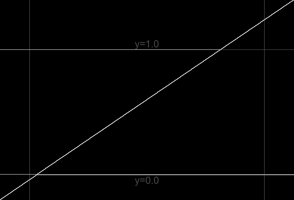
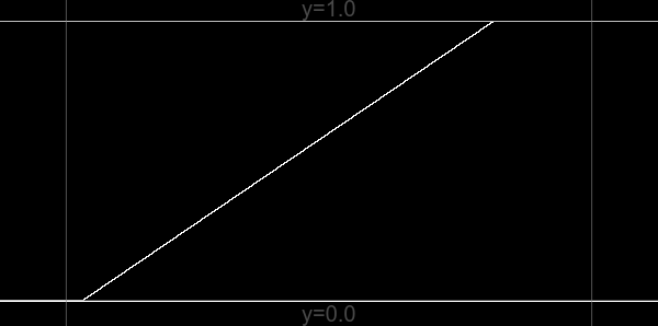
We can create a graph from this Nx1 image:
set HDR_SRC=ob_hdr.tiff

call %PICTBAT%graphLineNeg ^
  %HDR_SRC%
|
|
We push values into the [0..100%] box with different methods:
%IMG7%magick ^
  %HDR_SRC% ^
  -clamp ^
  ob_hdr_clamp.tiff

call %PICTBAT%graphLineNeg ^
  ob_hdr_clamp.tiff
"-clamp" zeros highlight and shadow contrast.
|
|
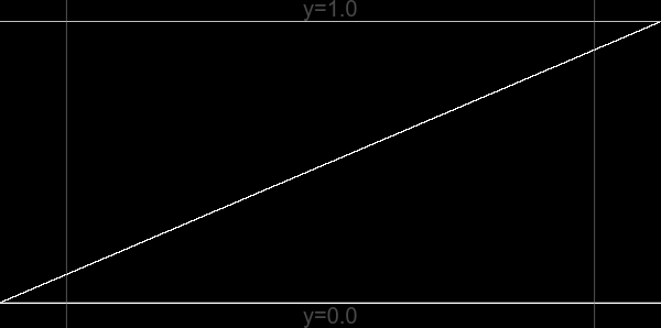
%IMG7%magick ^
  %HDR_SRC% ^
  -auto-level ^
  ob_hdr_autolev.tiff

call %PICTBAT%graphLineNeg ^
  ob_hdr_autolev.tiff
"-auto-level" reduces all contrast.
|
|
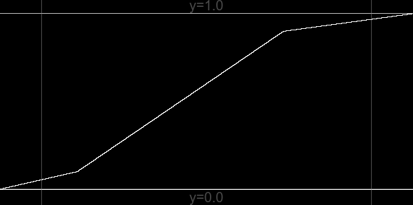
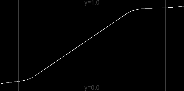
%IM7DEV%magick ^
  %HDR_SRC% ^
  -process 'oogbox method Linear' ^
  ob_hdr_lin.tiff

call %PICTBAT%graphLineNeg ^
  ob_hdr_lin.tiff
Linear method retains mid-tone contrast;
reduces highlight and shadow contrast;
second-order discontinuity may be obvious.
|
|
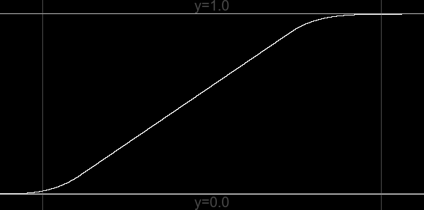
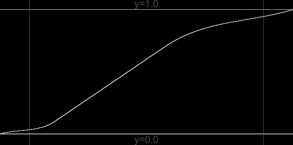
%IM7DEV%magick ^
  %HDR_SRC% ^
  -process 'oogbox method Power' ^
  ob_hdr_pow.tiff

call %PICTBAT%graphLineNeg ^
  ob_hdr_pow.tiff
Power method has no second-order discontinuity;
reduces highlight and shadow contrast,
with zero contrast at the extremes.
|
|
%IM7DEV%magick ^
  %HDR_SRC% ^
  -process 'oogbox method Blend' ^
  ob_hdr_blnd.tiff

call %PICTBAT%graphLineNeg ^
  ob_hdr_blnd.tiff
Blend method doesn't zero contrast anywhere.
|
|
%IM7DEV%magick ^
  %HDR_SRC% ^
  -process 'oogbox method Blend hiLimit 0.7' ^
  ob_hdr_blnd2.tiff

call %PICTBAT%graphLineNeg ^
  ob_hdr_blnd2.tiff
Any oogbox method may benefit from limits closer to 0.5.
|
|
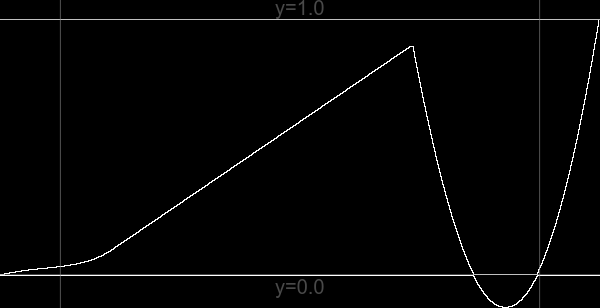
For "method blend", verbose output will state the calculated gradient of the linear part of the blend. This can be overridden, but larger values may result in tonal reversal. For example, with a very large value:
%IM7DEV%magick ^
  %HDR_SRC% ^
  -process 'oogbox method Blend hiGradient 9' ^
  ob_hdr_blnd3.tiff

call %PICTBAT%graphLineNeg ^
  ob_hdr_blnd3.tiff
|
|
When an image is encoded HCLp, and we convert to sRGB, is the sRGB image guaranteed to be in gamut? No. Hence, if we use HCLp to try and bring an sRGB OOG back into gamut, we should then test the sRGB result and apply a suitable process to that.
Can we invert the process? We haven't lost any pixel data, but we have lost the knowledge of how far OOG the image was. We can't reverse the process without this knowledge. If we know the original x0, x1, P0 and P1, and hence a, b, c and d, we can calculate the inverse transformation:
a' = 1/a
b' = x0
c' = 1/c
d' = x1 - c'
Currently loLimit and hiLimit are parameters from the user, defaulting to 0.1 and 0.9. Perhaps sensible values could be calculated somehow.
An adaptive (aka localised) oogbox would be useful, eg for increasing local contrast that can push cvalues outside range of 0..100%. Instead of applying a global curve, it would apply a series local curves. Implementation? Treat shadows and highlights separately. Find and apply the strongest curve needed for shadows, then blend with the input via a mask that defines how much of the effect we need.
For convenience, .bat scripts are also available in a single zip file. See
Zipped BAT files.
@rem From %1, a floating-point image that may contain values out of 0 to 100%,
@rem makes output %2 with all values within 0 to 100%.
@rem %3 limit for lower transformation.
@rem %4 limit for upper transformation.
@rem
@rem Assumes "magick" is HDRI.
@rem
@rem Updated:
@rem   6-August-2022 for IM v7
@rem


@if [%1]==[] findstr /B "rem @rem" %~f0 & exit /B 1

@setlocal enabledelayedexpansion

@call echoOffSave

rem call %PICTBAT%setInOut %1 olin


set INFILE=%~1

set OUTFILE=%2
if "%OUTFILE%"=="." set OUTFILE=
if "%OUTFILE%"=="" set OUTFILE=NULL:

set P0=%3
if "%P0%"=="." set P0=
if "%P0%"=="" set P0=0.1

set P1=%4
if "%P1%"=="." set P1=
if "%P1%"=="" set P1=0.9

set X0=
for /F "usebackq" %%L in (`%IM7DEV%magick ^
  %INFILE% ^
  -precision 16 ^
  -format "X0=%%[fx:minima]\nX1=%%[fx:maxima]\n" ^
  info:`) do set %%L
if "%X0%"=="" exit /B 1

:: FIXME: if X0 > -epsilon, don't calc a and b.
:: FIXME: if X1 < 1+epsilon, don't calc c and d.

set DO_LO=0
set DO_HI=0

set EPS=1e-5

set FMT=^
DO_LO=%%[fx:%X0%^<-%EPS%?1:0]\n^
DO_HI=%%[fx:%X1%^>1+%EPS%?1:0]\n

for /F "usebackq" %%L in (`%IMG7%magick identify ^
  -format "%FMT%" ^
  xc:`) do set %%L

set FMT=^
a=%%[fx:(-%P0%)/(%X0%-(%P0%))]\n^
b=%%[fx:%P0%*(%X0%)/(%X0%-(%P0%))]\n

for /F "usebackq" %%L in (`%IMG7%magick identify ^
  -precision 16 ^
  -format "%FMT%" ^
  xc:`) do set %%L

set FMT=^
c=%%[fx:(1-%P1%)/(%X1%-%P1%)]\n^
d=%%[fx:%P1%*(%X1%-1)/(%X1%-%P1%)]\n

for /F "usebackq" %%L in (`%IMG7%magick identify ^
  -precision 16 ^
  -format "%FMT%" ^
  xc:`) do set %%L


echo P0=%P0% P1=%P1%
echo DO_LO=%DO_LO% DO_HI=%DO_HI%
echo X0=%X0% X1=%X1%
echo a=%a% b=%b% c=%c% d=%d%

goto skip

%IM7DEV%magick ^
  %INFILE% ^
  ( -clone 0 ^
    -function Polynomial %c%,%d% ^
  ) ^
  ( -clone 0 ^
    -function Polynomial %a%,%b% ^
  ) ^
  ( -clone 0,1 ^
    -compose Darken -composite ^
  ) ^
  -delete 0,1 ^
  -compose Lighten -composite ^
  -depth 32 ^
  -define quantum:format=floating-point ^
  %OUTFILE%

:skip

set POLY_HI=
set POLY_LO=

if %DO_HI%==1 set POLY_HI=^
  ( -clone 0 ^
    -function Polynomial %c%,%d% ^
  ) ^
  -compose Darken -composite

if %DO_LO%==1 set POLY_LO=^
  ( -clone 0 ^
    -function Polynomial %a%,%b% ^
  ) ^
  -compose Lighten -composite

%IMG7%magick ^
  %INFILE% ^
  -define compose:clamp=off ^
  %POLY_HI% ^
  %POLY_LO% ^
  -depth 32 ^
  -define quantum:format=floating-point ^
  %OUTFILE%


call echoRestore

@endlocal & set olinOUTFILE=%OUTFILE%
@rem Applies oogLinear independently to three channels.
@rem Assumes "magick" is HDRI.
@rem
@rem Updated:
@rem   6-August-2022 for IM v7
@rem

@if [%1]==[] findstr /B "rem @rem" %~f0 & exit /B 1

@setlocal enabledelayedexpansion

@call echoOffSave

rem call %PICTBAT%setInOut %1 olin


set INFILE=%~1

set OUTFILE=%2
if "%OUTFILE%"=="." set OUTFILE=
if "%OUTFILE%"=="" set OUTFILE=NULL:

set P0=%3
if "%P0%"=="." set P0=
if "%P0%"=="" set P0=0.1

set P1=%4
if "%P1%"=="." set P1=
if "%P1%"=="" set P1=0.9

set TMP_FILE=\temp\ooglin3_%%d.miff
set TMP0=\temp\ooglin3_0.miff
set TMP1=\temp\ooglin3_1.miff
set TMP2=\temp\ooglin3_2.miff


for /F "usebackq" %%L in (`%IMG7%magick ^
  %INFILE% ^
  -format "COLSP=%%[colorspace]\n" ^
  +write info: ^
  -channel RGB ^
  -separate ^
  +channel ^
  -depth 32 ^
  -define "quantum:format=floating-point" ^
  +adjoin ^
  %TMP_FILE%`) do set %%L

call %PICTBAT%oogLinear %TMP0% %TMP0% %P0% %P1%
if ERRORLEVEL 1 exit /B 1
call %PICTBAT%oogLinear %TMP1% %TMP1% %P0% %P1%
if ERRORLEVEL 1 exit /B 1
call %PICTBAT%oogLinear %TMP2% %TMP2% %P0% %P1%
if ERRORLEVEL 1 exit /B 1

%IMG7%magick ^
  %TMP0% %TMP1% %TMP2% ^
  -combine ^
  -set colorspace %COLSP% ^
  -depth 32 ^
  -define "quantum:format=floating-point" ^
  %OUTFILE%

call echoRestore

@endlocal & set olinOUTFILE=%OUTFILE%
@rem From %1, a floating-point image that may contain values out of 0 to 100%,
@rem makes output %2 with all values within 0 to 100%.
@rem %3 limit for lower transformation.
@rem %4 limit for upper transformation.
@rem %5 colorspace that contains a lightness channel (eg Lab, HCL).
@rem %6 number of lightness channel (0, 1 or 2).
@rem
@rem Assumes "magick" is HDRI.
@rem
@rem Updated:
@rem   6-August-2022 for IM v7
@rem

@if [%1]==[] findstr /B "rem @rem" %~f0 & exit /B 1

@setlocal enabledelayedexpansion

@call echoOffSave

rem call %PICTBAT%setInOut %1 olin


set INFILE=%~1

set OUTFILE=%2
if "%OUTFILE%"=="." set OUTFILE=
if "%OUTFILE%"=="" set OUTFILE=NULL:

set P0=%3
if "%P0%"=="." set P0=
if "%P0%"=="" set P0=0.1

set P1=%4
if "%P1%"=="." set P1=
if "%P1%"=="" set P1=0.9

set COLSP=%5
if "%COLSP%"=="." set COLSP=
if "%COLSP%"=="" set COLSP=Lab

set CHNUM=%6
if "%CHNUM%"=="." set CHNUM=
if "%CHNUM%"=="" (
  if /I %COLSP%==Lab set CHNUM=0
)
if "%CHNUM%"=="" exit / 1

echo COLSP=%COLSP%  CHNUM=%CHNUM%

set TMP_PREF=\temp\ooglin1ch

set TMP_FILE=%TMP_PREF%_%%d.miff
set TMP0=%TMP_PREF%_0.miff
set TMP1=%TMP_PREF%_1.miff
set TMP2=%TMP_PREF%_2.miff

set TMP_CH=%TMP_PREF%_%CHNUM%.miff

for /F "usebackq" %%L in (`%IMG7%magick ^
  %INFILE% ^
  -format "OrigCOLSP=%%[colorspace]\n" ^
  +write info: ^
  -colorspace %COLSP% ^
  -channel RGB ^
  -separate ^
  +channel ^
  -depth 32 ^
  -define "quantum:format=floating-point" ^
  +adjoin ^
  %TMP_FILE%`) do set %%L

echo OrigCOLSP=%OrigCOLSP%

if "%OrigCOLSP%"=="" exit /B 1

call %PICTBAT%oogLinear %TMP_CH% %TMP_CH% %P0% %P1%
if ERRORLEVEL 1 exit /B 1

%IMG7%magick ^
  %TMP0% %TMP1% %TMP2% ^
  -combine ^
  -set colorspace %COLSP% ^
  -colorspace %OrigCOLSP% ^
  -depth 32 ^
  -define "quantum:format=floating-point" ^
  %OUTFILE%


call echoRestore

@endlocal & set olinOUTFILE=%OUTFILE%
@rem From %1, a floating-point image that may contain values out of 0 to 100%,
@rem makes output %2 with all values within 0 to 100%.
@rem %3 limit for lower transformation.
@rem %4 limit for upper transformation.
@rem
@rem Note that "-process oogbox' is much faster.
@rem
@rem Assumes "magick" is HDRI.
@rem
@rem Updated:
@rem   6-August-2022 for IM v7
@rem


@if [%1]==[] findstr /B "rem @rem" %~f0 & exit /B 1

@setlocal enabledelayedexpansion

@call echoOffSave

rem call %PICTBAT%setInOut %1 opow


set INFILE=%~1

set OUTFILE=%2
if "%OUTFILE%"=="." set OUTFILE=
if "%OUTFILE%"=="" set OUTFILE=NULL:

set P0=%3
if "%P0%"=="." set P0=
if "%P0%"=="" set P0=0.1

set P1=%4
if "%P1%"=="." set P1=
if "%P1%"=="" set P1=0.9

set X0=
for /F "usebackq" %%L in (`%IMG7%magick ^
  %INFILE% ^
  -precision 16 ^
  -format "X0=%%[fx:minima]\nX1=%%[fx:maxima]\n" ^
  info:`) do set %%L
if "%X0%"=="" exit /B 1

set DO_LO=0
set DO_HI=0

set EPS=1e-5

set FMT=^
DO_LO=%%[fx:%X0%^<-%EPS%?1:0]\n^
DO_HI=%%[fx:%X1%^>1+%EPS%?1:0]\n

for /F "usebackq" %%L in (`%IMG7%magick identify ^
  -format "%FMT%" ^
  xc:`) do set %%L

set FMT=^
B0=%%[fx:(%P0%-(%X0%))/(%P0%)]\n^
B1=%%[fx:(%X1%-(%P1%))/(1-(%P1%))]\n

for /F "usebackq" %%L in (`%IMG7%magick identify ^
  -precision 16 ^
  -format "%FMT%" ^
  xc:`) do set %%L

if ERRORLEVEL 1 exit /B 1

set FMT=^
A0=%%[fx:(%P0%)/pow(%P0%-(%X0%),%B0%)]\n^
A1=%%[fx:(1-%P1%)/pow(%X1%-%P1%,%B1%)]\n

for /F "usebackq" %%L in (`%IMG7%magick identify ^
  -precision 16 ^
  -format "%FMT%" ^
  xc:`) do set %%L


echo P0=%P0% P1=%P1%
echo DO_LO=%DO_LO% DO_HI=%DO_HI%
echo X0=%X0% X1=%X1%
echo A0=%A0% B0=%B0% A1=%A1% B1=%B1%

:: Only do each end if OOG.

set DO_BOTH=0
if %DO_LO%==1 if %DO_HI%==1 set DO_BOTH=1

if %DO_BOTH%==1 (
  set "sFX=u<%P0%?%A0%*pow(u-(%X0%),%B0%):u>%P1%?1-%A1%*pow(%X1%-u,%B1%):u"
) else if %DO_LO%==1 (
  set "sFX=u<%P0%?%A0%*pow(u-(%X0%),%B0%):u"
) else if %DO_HI%==1 (
  set "sFX=u>%P1%?1-%A1%*pow(%X1%-u,%B1%):u"
) else (
  set sFX=u
)

%IMG7%magick ^
  %INFILE% ^
  -precision 16 ^
  -fx "%sFX%" ^
  -clamp ^
  -depth 32 ^
  -define quantum:format=floating-point ^
  -format "min=%%[fx:minima]  max=%%[fx:maxima]\n" ^
  +write info: ^
  %OUTFILE%

call echoRestore

@endlocal & set opowOUTFILE=%OUTFILE%
All images on this page were created by the commands shown, using:
%IMG7%magick -version
Version: ImageMagick 7.1.1-20 Q16-HDRI x86 98bb1d4:20231008 https://imagemagick.org
Copyright: (C) 1999 ImageMagick Studio LLC
License: https://imagemagick.org/script/license.php
Features: Cipher DPC HDRI OpenCL OpenMP(2.0)
Delegates (built-in): bzlib cairo freetype gslib heic jng jp2 jpeg jxl lcms lqr lzma openexr pangocairo png ps raqm raw rsvg tiff webp xml zip zlib
Compiler: Visual Studio 2022 (193532217)
%IM7DEV%magick -version
Version: ImageMagick 7.1.0-33 beta Q32-HDRI x86_64 64b5fe68a:20220501 https://imagemagick.org
Copyright: (C) 1999 ImageMagick Studio LLC
License: https://imagemagick.org/script/license.php
Features: Cipher DPC HDRI Modules OpenMP(4.5)
Delegates (built-in): bzlib fpx jbig jpeg lcms ltdl lzma tiff webp x xml zip zlib
Compiler: gcc (11.3)
To improve internet download speeds, some images may have been automatically converted (by ImageMagick, of course) from PNG or TIFF or MIFF to JPG.
Source file for this web page is oogbox.h1. To re-create this web page, execute "procH1 oogbox".
This page, including the images, is my copyright. Anyone is permitted to use or adapt any of the code, scripts or images for any purpose, including commercial use.
Anyone is permitted to re-publish this page, but only for non-commercial use.
Anyone is permitted to link to this page, including for commercial use.
Page version v1.0 15-November-2017.
Page created 02-Mar-2024 17:47:18.
Copyright © 2024 Alan Gibson.