set SRC=c3d_src.png

call %PICTBAT%gridOver ^
  toes.png %SRC% 8 8
We distort the image plane, like curving a piece of paper.
Curving an image in three-dimensional space is easily performed by ray-tracers such as POV-ray. The ray-tracer can create displacement maps and lighting masks for known surfaces so ImageMagick can apply them to any arbitrary input image.
However, some curved surfaces can be directly modelled with just ImageMagick. The method show here is not geometrically accurate for perspective views, but is good enough for some purposes.
Given an input image and a line that represents the cross-section of a surface, make a 2-D image that resembles the input curved into the surface.
Imagine the input image is printed on a sheet of paper. We can curve this paper in a number of ways, and even fold it. However, we will not cut the paper, nor will we stretch it.
In addition, we will curve the input image along the x-dimension only. Straight horizontal lines will become curved, but vertical lines will remain straight.
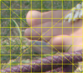
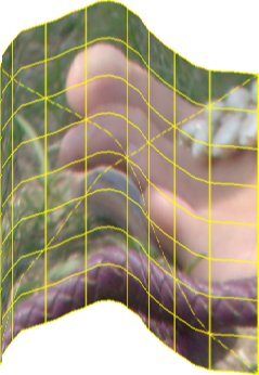
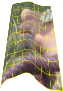
We will distort this input image:
set SRC=c3d_src.png call %PICTBAT%gridOver ^ toes.png %SRC% 8 8 |
|
Images don't usually have grids, but this helps us see what is happening.
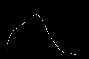
First, we need the profile of the curve we want to make. This is a cross-section of the 3-D curve. For a cylinder, it would be a circle. However, it must have two ends.
I use Gimp to draw a thin white line on a black background. The line can start and end anywhere, but it must not cross itself.
|
c3d_line.png |
|
The size of the image that contains the line is of no significance. The length of the line is significant, and so is the width it occupies within the image. We find the bounding rectangle of the line with the script colTrim.bat. An alternative method is to use "-connected-components".
call %PICTBAT%colTrim c3d_line.png Black

echo ctRECT=%ctRECT%  ctW=%ctW%  ctH=%ctH%
ctRECT=239x137+22+49 ctW=239 ctH=137
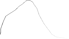
The script dp2Grad.bat finds the two ends of the line, and the length of the line in pixels. It also creates a gradient along the line that is black at one end, white at the other. Pixels that are not on the line are made transparent. (The morphology operation, and hence the entire script, is horribly slow.) We trim the result to just the line.
call %PICTBAT%dp2grad ^
  c3d_line.png ^
  c3d_grad.png

%IMG7%magick ^
  c3d_grad.png ^
  -crop %ctRECT% +repage ^
  c3d_grad.png

echo dp2gLINE_LEN=%dp2gLINE_LEN% dp2gERR=%dp2gERR%
dp2gLINE_LEN= dp2gERR=0 |
|
dp2grad writes some properties to the file.
%IMG7%magick identify -format %%[line:*] c3d_grad.png
line:len=368
line:x0=22
line:x1=260
line:y0=169
line:y1=185
We can read these to environment variables. In Windows, variable names can't contain colons (:), so we change them to underscores.
for /F "usebackq" %%L in (`%IMG7%magick identify ^
  -format %%[line:*] ^
  c3d_grad.png`) do (
  set LINE=%%L
  set !LINE::=_!
)

set line_
line_len=368
line_x0=22
line_x1=260
line_y0=169
line_y1=185
The length of the line needs to be equal to the width of the input image. Currently, the line is too long. We could rectify this by shrinking the line. (For precision, we might then re-calculate the length, and repeat until the length is sufficiently close.) Instead, we will enlarge the input image. We also need the new dimensions.
for /F "usebackq" %%L in (`%IMG7%magick ^
  %SRC% ^
  -resize %line_len%x ^
  -format "INP_WW=%%w\nINP_HH=%%h" ^
  +write info: ^
  c3d_res_inp.png`) do set %%L

echo INP_WW=%INP_WW% INP_HH=%INP_HH%
INP_WW=368 INP_HH=321 |
|
We fill the transparent areas by filling vertically. (See Filling holes: fill by shift.)
rem set sfFLAT_COL=None call %PICTBAT%shiftFill ^ c3d_grad.png 0x c3d_fill.png rem set sfFLAT_COL= |

|
If the line hasn't doubled back on itself, the rows will be equal. The top row represents a horizontal absolute displacement map, to transform an input image to the curved surface.
We crop the top row and scale it to the required height (INP_HH). It is the correct scale horizontally, but needs to be extended to the right to match the input.
%IMG7%magick ^ c3d_fill.png ^ -crop 0x1+0+0 +repage ^ -scale "x%INP_HH%^!" ^ -gravity West ^ -background White ^ -extent %INP_WW%x%INP_HH% ^ c3d_xdisp.png |

|
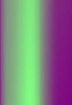
From c3d_xdisp.png, we make a complete absolute displacement map.
|
Make the map. %IMG7%magick ^
c3d_xdisp.png ^
( -clone 0 ^
-sparse-color bilinear ^
"0,0 Black 0,%%[fx:h-1] White" ^
) ^
( -clone 0 ^
-fill gray(50%%) -colorize 100 ^
) ^
-combine ^
-set colorspace sRGB ^
c3d_x_abs.png
|

|
|
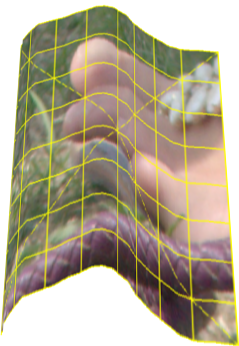
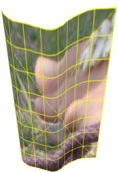
Apply the map, and crop. %IMG7%magick ^ c3d_res_inp.png ^ c3d_x_abs.png ^ -compose Distort ^ -set option:compose:args 100%%x100%% ^ -composite ^ -crop %ctW%x+0+0 +repage ^ c3d_xdisp_trial.png |

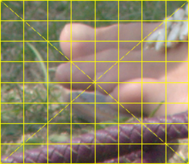
|
If we took a photo from an infinite distance of our input image wrapped onto the surface, looking directly at the surface, this is what the resulting photo would look like.
Instead of looking directly at the surface, we might view it from an angle. This is equivalent to rotating the surface around the x-axis by an angle α. This has two effects:
The angle is between -90° and +90°. If the angle is zero, we have no y-displacement. At either extreme, we see the exact profile, with none of the input image.
The total height of the output will be the sum of the foreshortened height of the input, plus the foreshortened height of the profile. This is INP_HH * cos(α) + ctH * |sin(α)| where INP_HH and ctH are given above.
set ALPHA=30

set ALPH_RAD=(%ALPHA%*3.1415926/180)

for /F "useback" %%L in (`%IMG7%magick identify ^
  -format "inHcosA=%%[fx:%INP_HH% * cos(%ALPH_RAD%)]\nctHsinA=%%[fx:%ctH% * sin(%ALPH_RAD%)]"
  xc:`) do set %%L

for /F "useback" %%L in (`%IMG7%magick identify ^
  -format "OUT_HH=%%[fx:%inHcosA% + %ctHsinA%]\nctHsinA_2=%%[fx:%ctHsinA%/2]"
  xc:`) do set %%L

echo inHcosA=%inHcosA% ctHsinA=%ctHsinA% ctHsinA_2=%ctHsinA_2% OUT_HH=%OUT_HH%
inHcosA=277.994 ctHsinA=68.5 ctHsinA_2=34.25 OUT_HH=346.494
We can get a height field from the cross section by trimming to the line, turning the pixels beneath it white, and scaling to a single row. This will be used for any y-displacement.
%IMG7%magick ^ c3d_line.png ^ -crop %ctRECT% +repage ^ -morphology dilate rectangle:1x%ctH%+0+0 ^ -scale "x1^!" ^ c3d_ht_fld.png |
|
From c3d_ht_fld.png, we can make a relative displacement map.
|
Make the map. %IMG7%magick ^
c3d_ht_fld.png ^
( -clone 0 ^
-fill gray(50%%) -colorize 100 ^
) ^
( -clone 1 ) ^
-swap 0,1 ^
-combine ^
-set colorspace sRGB ^
-scale "x%OUT_HH%^!" ^
c3d_y_rel.png
|

|
|
Apply the map. %IMG7%magick ^ c3d_xdisp_trial.png ^ -scale "x%inHcosA%^!" ^ -gravity Center -background None ^ -extent "x%OUT_HH%^!" ^ c3d_y_rel.png ^ -virtual-pixel None ^ -compose Displace ^ -set option:compose:args 0x%ctHsinA_2% ^ -composite ^ c3d_ydisp_trial.png |
|
This is like taking a photo of the curved image from an infinite distance, with no perspective ("parallel projection").
We can simulate perspective by:
For effect (1) and (2), we "+level" the map, to push values towards 50%. We apply this to a clone of the entire map, and blend this with the original map by composing "over" with a mask.
|
Revise the map. %IMG7%magick ^
c3d_y_rel.png ^
( +clone ^
+level 10%% ^
) ^
( +clone ^
-sparse-color bilinear "0,0,White 0,%%[fx:h-1],Black" ^
) ^
-composite ^
c3d_y_persp.png
|
|
We use this revised map, and apply the narrowing process.
|
Apply perspective. set NARROW_PC=10 set dNarrow=(w*%NARROW_PC%/100) set PERSP=^ 0,0,%%[fx:%dNarrow%],0,^ %%[fx:w-1],0,%%[fx:w-1-%dNarrow%],0,^ 0,%%[fx:h-1],0,%%[fx:h-1],^ %%[fx:w-1],%%[fx:h-1],%%[fx:w-1],%%[fx:h-1] %IMG7%magick ^ c3d_xdisp_trial.png ^ -scale "x%inHcosA%^!" ^ -gravity Center -background None ^ -extent "x%OUT_HH%^!" ^ c3d_y_persp.png ^ -virtual-pixel None ^ -compose Displace ^ -set option:compose:args 0x%ctHsinA_2% ^ -composite ^ -virtual-pixel None ^ -distort Perspective "%PERSP%" ^ c3d_ydisp_persp.png |
|
Because the profile height has reduced at the top (the back of the 3-D object), the overall result is shorter than OUT_HH.
The shortening of the profile height is not quite accurate (it varies at each cross-section), but visually appears realistic. Similarly, for correct 3-D, the distance between parallels on the ridge should be greater than the distance in the valleys, but this has reduced the distance. For ordinary photographs without grids, these defects should not be noticable.
We encapsulate the above in the script curve3d.bat.
| Make
line file |
Line file | Run script | Output |
|---|---|---|---|
|
c3d_line.png |
|
call %PICTBAT%curve3d ^ %SRC% c3d_line.png ^ c3d_s1.png |
|
|
c3d_line.png |
|
call %PICTBAT%curve3d ^ %SRC% c3d_line.png ^ c3d_s2.png ^ 20 20 20 |
|
|
c3d_line.png |
|
call %PICTBAT%curve3d ^ %SRC% c3d_line.png ^ c3d_s3.png ^ -20 20 20 |
|
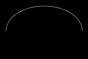
%IMG7%magick ^
  -size 300x200 ^
  xc:Black ^
  +antialias ^
  -stroke White -fill None ^
  -draw ^
    "arc 20,190 280,20 180,0" ^
  c3d_arc.png
|
|
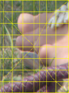
call %PICTBAT%curve3d ^ %SRC% c3d_arc.png ^ c3d_s4.png ^ -20 20 20 |
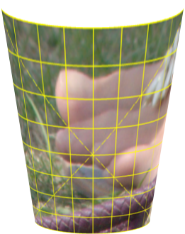
|
%IMG7%magick ^
  -size 300x200 ^
  xc:Black ^
  +antialias ^
  -stroke White -fill None ^
  -draw ^
    "ellipse 150,100 130,80 0,360" ^
  -stroke Black ^
  -draw "line 150,100 150,199" ^
  c3d_ellip.png
The black line breaks the circle
|
|
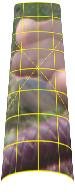
call %PICTBAT%curve3d ^ %SRC% c3d_ellip.png ^ c3d_s5.png ^ 20 20 20 |
|
The methods shown here could be extended:
For convenience, .bat scripts are also available in a single zip file. See Zipped BAT files.
rem Find trim rectangle for border of given colour.
@rem
@rem Updated:
@rem   21-August-2022 for IM v7.
@rem

@if "%1"=="" findstr /B "rem @rem" %~f0 & exit /B 1

@setlocal

@call echoOffSave

call %PICTBAT%setInOut %1 ct

set BORD_COL=%2
if "%BORD_COL%"=="." set BORD_COL=
if "%BORD_COL%"=="" set BORD_COL=Black

if not "%3"=="" set OUTFILE=%3


for /F "usebackq tokens=1-4 delims=x+" %%A in (`%IMG7%magick ^
  %INFILE% ^
  -bordercolor %BORD_COL% ^
  -border 1 ^
  -format "%%@" ^
  info:`) do (
  set /A BW=%%A
  set /A BH=%%B
  set /A BX=%%C-1
  set /A BY=%%D-1
)


call echoRestore

endlocal & set ctW=%BW%& set ctH=%BH%& set ctX=%BX%& set ctY=%BY%& set ctRECT=%BW%x%BH%+%BX%+%BY%
rem Given image %1 a white line on black background,
rem finds coords of the ends,
rem and makes output image %2 that has gradient for the line,
rem and transparent elsewhere.
rem Sets properties "line:*" in output.
@rem
@rem Updated:
@rem   20-August-2022 for IM v7.
@rem

@if "%1"=="" findstr /B "rem @rem" %~f0 & exit /B 1

@setlocal

rem @call echoOffSave

call %PICTBAT%setInOut %1 dp2g

if not "%2"=="" set OUTFILE=%2


set TMP_2ENDS=l2g_two_ends.miff

set ERR=0

set X0=
for /F "usebackq tokens=2,3 delims=:, " %%X in (`%IM7DEV%magick ^
  %INFILE% ^
  -virtual-pixel Black ^
  -morphology HMT LineEnds ^
  -process onewhite ^
  %TMP_2ENDS% 2^>^&1`) do (
  set X0=%%X
  set Y0=%%Y
)
if "%X0%"=="" exit /B 1

if "%X0%"=="none" (
  echo %0: no line ends [%INFILE%]
  set ERR=1
  goto end
)

for /F "usebackq tokens=2,3 delims=:, " %%X in (`%IM7DEV%magick ^
  %TMP_2ENDS% ^
  -fill Black -draw "point %X0%,%Y0%" ^
  -process onewhite ^
  NULL: 2^>^&1`) do (
  set X1=%%X
  set Y1=%%Y
)

if "%X1%"=="none" (
  echo %0: no second line end [%INFILE%]
  set ERR=1
  goto end
)


set nInPath=
for /F "usebackq tokens=1-2 delims=: " %%L in (`%IM7DEV%magick ^
  %INFILE% ^
  -negate ^
  -evaluate Subtract 1 -clamp -evaluate Add 1 ^
  -set colorspace sRGB ^
  -process ^
    "darkestpntpnt s %X0%,%Y0% e %X1%,%Y1% t 0.5 data v" ^
  -channel G -separate +channel ^
  -clamp ^
  -auto-level ^
  +depth ^
  %OUTFILE% 2^>^&1`) do (
  if /I "%%L"=="nInPath" set nInPath=%%M
  if /I "%%L"=="maxDist" set MaxDist=%%M
  if /I "%%L"=="Bug:" set ERR=1
)
if "%nInPath%"=="" exit /B 1

%IMG7%magick ^
  %OUTFILE% ^
  %INFILE% ^
  -compose CopyOpacity -composite ^
  -background gray(50%%) -alpha Background ^
  -auto-level ^
  -alpha Background ^
  -set line:len %nInPath% ^
  -set line:x0 %X0% ^
  -set line:y0 %Y0% ^
  -set line:x1 %X1% ^
  -set line:y1 %Y1% ^
  %OUTFILE%

:end

call echoRestore

endlocal & set dp2gOUTFILE=%OUTFILE%& set dp2gERR=%ERR%
The methods shown on this page originally used line2Grad.bat. Now, dp2Grad.bat does the same job but is much quicker.
rem Given image %1 a white line on black background,
rem finds coords of the ends,
rem and makes output image %2 that has gradient for the line,
rem and transparent elsewhere.
rem Sets properties "line:*" in output.
@rem
@rem Updated:
@rem   3-September-2022 for IM v7.
@rem


@if "%1"=="" findstr /B "rem @rem" %~f0 & exit /B 1

@setlocal

@call echoOffSave

call %PICTBAT%setInOut %1 l2g

if not "%2"=="" set OUTFILE=%2


set TMP_2ENDS=l2g_two_ends.miff
set TMP_LINE_GRAD=l2g_grad.png

set APPROX_LEN_PC=90

set ERR=0


set WW=

for /F "usebackq" %%L in (`%IMG7%magick identify ^
  -format "WW=%%w\nHH=%%h\nDIAG=%%[fx:int(hypot(w,h)+0.5)]" ^
  %INFILE%`) do set %%L

if "%WW%"=="" (
  echo Can't open [%INFILE%]
  exit /B 1
)


for /F "usebackq tokens=2,3 delims=:, " %%X in (`%IM7DEV%magick ^
  %INFILE% ^
  -virtual-pixel Black ^
  -morphology HMT LineEnds ^
  -process onewhite ^
  %TMP_2ENDS% 2^>^&1`) do (
  set X0=%%X
  set Y0=%%Y
)

if "%X0%"=="none" (
  echo %0: no line ends [%INFILE%]
  set ERR=1
  goto end
)

for /F "usebackq tokens=2,3 delims=:, " %%X in (`%IM7DEV%magick ^
  %TMP_2ENDS% ^
  fill Black -draw "point %X0%,%Y0%" ^
  -process onewhite ^
  NULL: 2^>^&1`) do (
  set X1=%%X
  set Y1=%%Y
)

if "%X1%"=="none" (
  echo %0: no second line end [%INFILE%]
  set ERR=1
  goto end
)

:: FIXME:
:: If X1 < X0, swap the ends.
:: If X1==X0 and Y1 < Y0, swap the ends.

rem echo X0=%X0% Y0=%Y0% X1=%X1% Y1=%Y1%

for /F "usebackq" %%L in (`%IMG7%magick ^
  %INFILE% ^
  -format "APPROX_LEN=%%[fx:int(max(hypot(%X1%-%X0%,%Y1%-%Y0%),mean*w*h+0.5))]" ^
  INFO:`) do set %%L

rem echo APPROX_LEN=%APPROX_LEN%

set /A KNL_SCALE_V=65535*%APPROX_LEN_PC%/%APPROX_LEN%/100

rem echo KNL_SCALE_V=%KNL_SCALE_V%

%IMG7%magick ^
  %INFILE% ^
  -negate +write mpr:MASK ^
  -fill White -colorize 100 ^
  -fill Black -draw "point %X0%,%Y0%" ^
  -write-mask mpr:MASK ^
  -morphology ^
    IterativeDistance:%DIAG% ^
    Euclidean:7,%KNL_SCALE_V% ^
  +write-mask ^
  +depth ^
  %TMP_LINE_GRAD%

for /F "usebackq" %%L in (`%IMG7%magick ^
  %INFILE% ^
  %TMP_LINE_GRAD% ^
  -compose Darken -composite ^
  -format "MAX_01=%%[fx:maxima]\nMAX_GRAY=%%[fx:maxima*QuantumRange]\nLINE_LEN=%%[fx:maxima*QuantumRange/%KNL_SCALE_V%]" ^
  info:`) do set %%L

rem echo MAX_01=%MAX_01% MAX_GRAY=%MAX_GRAY% LINE_LEN=%LINE_LEN%

if "%MAX_01%"=="1" (
  echo %0: Bad first MAX_01 == %MAX_01%
  set ERR=1
  goto end
)

for /F "usebackq" %%L in (`%IMG7%magick ^
  %INFILE% ^
  %TMP_LINE_GRAD% ^
  -compose Darken -composite ^
  -format "KNL_SCALE_V=%%[fx:%KNL_SCALE_V%/maxima)]" ^
  info:`) do set %%L

rem echo KNL_SCALE_V=%KNL_SCALE_V%

%IMG7%magick ^
  %INFILE% ^
  -negate +write mpr:MASK ^
  -fill White -colorize 100 ^
  -fill Black -draw "point %X0%,%Y0%" ^
  -write-mask mpr:MASK ^
  -morphology ^
    IterativeDistance:%DIAG% ^
    Euclidean:7,%KNL_SCALE_V% ^
  +write-mask ^
  +depth ^
  %TMP_LINE_GRAD%

for /F "usebackq" %%L in (`%IMG7%magick ^
  %INFILE% ^
  %TMP_LINE_GRAD% ^
  -compose Darken -composite ^
  -format "MAX_01=%%[fx:maxima]\nMAX_GRAY=%%[fx:maxima*QuantumRange]\nLINE_LEN=%%[fx:maxima*QuantumRange/%KNL_SCALE_V%]" ^
  info:`) do set %%L

rem echo MAX_01=%MAX_01% MAX_GRAY=%MAX_GRAY% LINE_LEN=%LINE_LEN%

:: "%MAX_01%" should be "1", more or less.
:: MAX_GRAY should be >= QuantumRange - KNL_SCALE_V

for /F "usebackq" %%L in (`%IMG7%magick identify ^
  -format "GRAY_OK=%%[fx:%MAX_GRAY%>QuantumRange-%KNL_SCALE_V%?1:0]"
  xc:`) do set %%L

if not "%GRAY_OK%"=="1" (
  echo %0: Bad second MAX_01 = %MAX_01% MAX_GRAY = %MAX_GRAY%
  set ERR=1
  goto end
)

%IMG7%magick ^
  %TMP_LINE_GRAD% ^
  %INFILE% ^
  -compose CopyOpacity -composite ^
  -background gray(50%%) -alpha Background ^
  -auto-level ^
  -alpha Background ^
  -set line:len %LINE_LEN% ^
  -set line:x0 %X0% ^
  -set line:y0 %Y0% ^
  -set line:x1 %X1% ^
  -set line:y1 %Y1% ^
  %OUTFILE%

:end

call echoRestore

endlocal & set l2gOUTFILE=%OUTFILE%& set l2gLINE_LEN=%LINE_LEN%&set l2gERR=%ERR%
rem From image %1
rem and profile %2 (white line on black background),
rem creates output %3, curving the image around the extruded profile.
rem %4 is tilt of object. >0 tilts up (ie camera tilt down).
rem %5 is percentage perspective narrowing (0=no perspective).
rem %6 is percentage perspective shortening
@rem
@rem  Updated:
@rem    20-August-2022 Upgraded for IM v7.
@rem


@if "%2"=="" findstr /B "rem @rem" %~f0 & exit /B 1

@setlocal enabledelayedexpansion

@call echoOffSave

call %PICTBAT%setInOut %1 c3d


set LINE_FILE=%2
set LINE_BASE=%~n2

if not "%3"=="" if not "%3"=="." set OUTFILE=%3

set ALPHA=%4
if "%ALPHA%"=="." set ALPHA=
if "%ALPHA%"=="" set ALPHA=0

set NARROW_PC=%5
if "%NARROW_PC%"=="." set NARROW_PC=
if "%NARROW_PC%"=="" set NARROW_PC=0

set SHORTEN_PC=%6
if "%SHORTEN_PC%"=="." set SHORTEN_PC=
if "%SHORTEN_PC%"=="" set SHORTEN_PC=0

:: FIXME if alpha less than 0, different perspective.

call %PICTBAT%colTrim %LINE_FILE% Black

echo ctRECT=%ctRECT%  ctW=%ctW%  ctH=%ctH%

:: Grad file is named after the line, not the first input file.

set GRAD_FILE=%LINE_BASE%_c3d_grad.miff
set TMP_INPUT=c3d_tmp_inp.miff
set FILL_FILE=c3d_fill.miff
set XDISP_TRIAL=c3d_xdisp_trial.miff
set Y_PERSP=c3d_y_persp.miff

echo GRAD_FILE=%GRAD_FILE%

:: For better performance, don't delete GRAD_FILE.
::
del %GRAD_FILE% 2>nul

set line_len=
if exist %GRAD_FILE% (

  for /F "usebackq" %%L in (`%IMG7%magick identify ^
    -format %%[line:*] ^
    %GRAD_FILE%`) do (
    set LINE=%%L
    set !LINE::=_!
  )
)

if "%line_len%"=="" (
  call %PICTBAT%dp2grad ^
    %LINE_FILE% ^
    %GRAD_FILE%

  %IMG7%magick ^
    %GRAD_FILE% ^
    -crop %ctRECT% +repage ^
    %GRAD_FILE%

  for /F "usebackq" %%L in (`%IMG7%magick identify ^
    -format %%[line:*] ^
    %GRAD_FILE%`) do (
    set LINE=%%L
    set !LINE::=_!
  )
)

echo line_len=%line_len% dp2gERR=%dp2gERR%
if "%line_len%"=="" exit /B 1

for /F "usebackq" %%L in (`%IMG7%magick ^
  %INFILE% ^
  -resize %line_len%x ^
  -format "INP_WW=%%w\nINP_HH=%%h" ^
  +write info: ^
  %TMP_INPUT%`) do set %%L

echo INP_WW=%INP_WW% INP_HH=%INP_HH%


call %PICTBAT%shiftFill ^
  %GRAD_FILE% 0x %FILL_FILE%

if ERRORLEVEL 1 exit /B 1

%IMG7%magick ^
  %FILL_FILE% ^
  -crop 0x1+0+0 +repage ^
  -scale "x%INP_HH%^!" ^
  -gravity West ^
  -background White ^
  -extent %INP_WW%x%INP_HH% ^
  ( -clone 0 ^
    -sparse-color bilinear ^
      "0,0 Black 0,%%[fx:h-1] White" ^
  ) ^
  ( -clone 0 ^
    -fill gray(50%%) -colorize 100 ^
  ) ^
  -combine ^
  -set colorspace sRGB ^
  %TMP_INPUT% ^
  +swap ^
  -compose Distort ^
  -set option:compose:args 100%%x100%% ^
  -composite ^
  -crop %ctW%x+0+0 +repage ^
  %XDISP_TRIAL%


set ALPH_RAD=(%ALPHA%*PI/180)

for /F "useback" %%L in (`%IMG7%magick identify ^
  -format "inHcosA=%%[fx:%INP_HH% * cos(%ALPH_RAD%)]\nctHsinA=%%[fx:%ctH% * abs(sin(%ALPH_RAD%))]"
  xc:`) do set %%L

for /F "useback" %%L in (`%IMG7%magick identify ^
  -format "OUT_HH=%%[fx:%inHcosA% + %ctHsinA%]\nctHsinA_2=%%[fx:%ctHsinA%/2]\nIS_NEG=%%[fx:%ALPHA%<0?1:0]"
  xc:`) do set %%L

echo inHcosA=%inHcosA% ctHsinA=%ctHsinA% ctHsinA_2=%ctHsinA_2% OUT_HH=%OUT_HH% IS_NEG=%IS_NEG%

set dNarrow=w*%NARROW_PC%/100

if %IS_NEG%==1 (

  echo Angle is negative: %ANGLE%

  set sNEG_Y=-negate

  set PERSP=^
0,0,0,0,^
%%[fx:w-1],0,%%[fx:w-1],0,^
0,%%[fx:h-1],%%[fx:%dNarrow%],%%[fx:h-1],^
%%[fx:w-1],%%[fx:h-1],%%[fx:w-1-%dNarrow%],%%[fx:h-1]

) else (

  echo Angle is positive: %ANGLE%

  set sNEG_Y=

  set PERSP=^
0,0,%%[fx:%dNarrow%],0,^
%%[fx:w-1],0,%%[fx:w-1-%dNarrow%],0,^
0,%%[fx:h-1],0,%%[fx:h-1],^
%%[fx:w-1],%%[fx:h-1],%%[fx:w-1],%%[fx:h-1]

)

%IMG7%magick ^
  %LINE_FILE% ^
  -crop %ctRECT% +repage ^
  -morphology dilate rectangle:1x%ctH%+0+0 ^
  -scale "x1^!" ^
  ( -clone 0 ^
    -fill gray(50%%) -colorize 100 ^
  ) ^
  ( -clone 1 ) ^
  -swap 0,1 ^
  -combine ^
  -set colorspace sRGB ^
  -scale "x%OUT_HH%^!" ^
  %sNEG_Y% ^
  ( +clone ^
    +level %SHORTEN_PC%%% ^
  ) ^
  ( +clone ^
    -sparse-color bilinear "0,0,White 0,%%[fx:h-1],Black" ^
  ) ^
  -composite ^
  %Y_PERSP%

%IMG7%magick ^
  %XDISP_TRIAL% ^
  -scale "x%inHcosA%^!" ^
  -gravity Center -background None ^
  -extent "x%OUT_HH%^!" ^
  %Y_PERSP% ^
  -virtual-pixel None ^
  -compose Displace ^
  -set option:compose:args 0x%ctHsinA_2% ^
  -composite ^
  -virtual-pixel None ^
  -distort Perspective "%PERSP%" ^
  %OUTFILE%


call echoRestore

endlocal & set c3dOUTFILE=%OUTFILE%
All images on this page were created by the commands shown, using:
%IMG7%magick -version
Version: ImageMagick 7.1.0-42 Q16-HDRI x64 396d87c:20220709 https://imagemagick.org
Copyright: (C) 1999 ImageMagick Studio LLC
License: https://imagemagick.org/script/license.php
Features: Cipher DPC HDRI OpenCL
Delegates (built-in): bzlib cairo freetype gslib heic jng jp2 jpeg jxl lcms lqr lzma openexr pangocairo png ps raqm raw rsvg tiff webp xml zip zlib
Compiler: Visual Studio 2022 (193231332)
Source file for this web page is curve3d.h1. To re-create this web page, execute "procH1 curve3d".
This page, including the images, is my copyright. Anyone is permitted to use or adapt any of the code, scripts or images for any purpose, including commercial use.
Anyone is permitted to re-publish this page, but only for non-commercial use.
Anyone is permitted to link to this page, including for commercial use.
Page version v1.0 2-May-2016.
Page created 08-Sep-2022 11:01:17.
Copyright © 2022 Alan Gibson.