call %PICTBAT%mkSqTile ^
  w2s_sampin.png 650 100
Rendering very wide images into aspect ratios that are closer to squares.
Some images, such as panoramas, have extreme aspect ratios. For example, an image may be 25 times as wide as it is tall, so the ratio is 25:1. This is a problem when displaying the image on fixed-size media that are closer to squares, such as computer screens. We can view either a small part of the image, or heavily shrink the entire image to fit the screen width, wasting most of the screen area.
This page shows a number of alternatives that renders a high-aspect ratio into an area with a smaller aspect ratio.
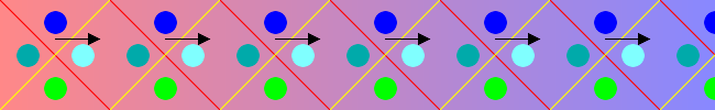
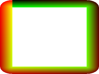
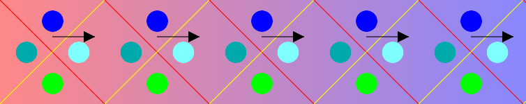
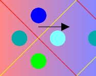
Methods shown on this page distort wide images in various ways. To test accuracy, we will use a graphic image constructed with the script mkSqTile.bat. We can make the dimensions anything we like.
call %PICTBAT%mkSqTile ^ w2s_sampin.png 650 100 |
|
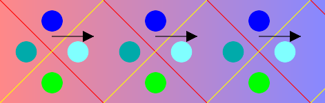
In this image: blue circles are at the top (think of a blue sky); green circles are at the bottom (think of green grass); the arrows run from left to right.
In some methods, lines that are vertical in the input image remain vertical in the result image. In some methods, vertical input lines become radii around a central point. Other methods are more complex.
Some methods directly distort an input image. Other methods create a displacement map, that can be used to distort an image. And one method (path2ribbon.bat) uses a line that defines a path to create a displacement map.
Some methods here use -distort polar, or -fx as an alternative. The -distort polar operation makes an output the same size as the first input, so we need to resize that to the required output size. As the image that is input to the script will often be the same scale as the required output, the resize will usually shrink the image. But then -distort polar will enlarge its input pixels, so the image is first shrunk, then enlarged to its original scale. This inevitably blurs the image.
The -fx method doesn't need to resize (shrink) the image, so avoids the blurring problem.
If a script is called but not output file is specified, the script will run without making an output image. This is useful in a workflow that needs to know how long the output path would be.
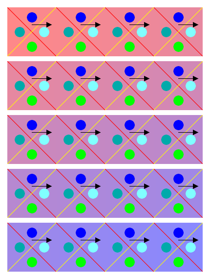
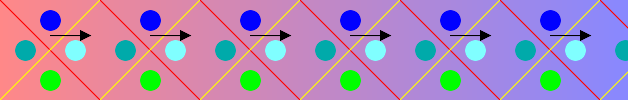
We crop the input image into strips, which we append with a small gap. The gap is made by extending the bottom of each crop. After the append, we crop the bottom extension off, then add an overall margin.
To demonstrate, we create a input image.
call %PICTBAT%mkSqTile ^
  w2s_test_strip1.png 2000 100
We make the striped image:
set nStrips=5
set stripGap=10
set margin=15

%IMG7%magick ^
  w2s_test_strip1.png ^
  -set option:HH %%h ^
  -crop %nStrips%x1@ +repage ^
  -background None -extent %%wx%%[fx:h+%stripGap%] ^
  -append +repage ^
  -crop %%wx%%[fx:%nStrips%*%%[HH]+(%nStrips%-1)*%stripGap%]+0+0 ^
    +repage ^
  -bordercolor None -border %margin% ^
  w2s_strip1.png
|
|
If the input width is not exactly divible by nStrips, the widths of the strips will vary by one. For short strips, we could append the first column of each strip to the end of the previous strip.
This method is very simple. All the strips have the same orientation as the input. Unfortunately, the result isn't obviously a panorama. To make this more obvious, we might overlap the strips, so objects at the right side of a strip are repeated at the left end of the next strip.
These enclose rectangular holes.
Corners can be mitre or rounded (elliptical).
Mitre corners might repeat outer, or trim inner, or both (ie mid-line is continuous).
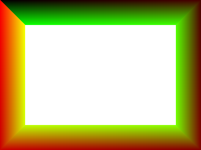
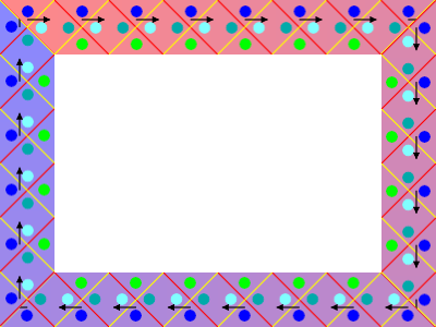
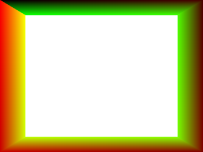
The script mkDispMapRectFrame.bat creates an absolute distortion map for a mitred rectangular frame, which we can use to distort the input image.
call %PICTBAT%mkDispMapRectFrame ^
  w2s_rectf1.png 400 300 50 50

echo rfTotLen=%rfTotLen%
rfTotLen=1400 |
|
|
Make a suitable test image, and distort it. call %PICTBAT%mkSqTile ^
w2s_test_rf1.png %rfTotLen% 50
%IMG7%magick ^
w2s_rectf1.png ^
( +clone -alpha extract -write mpr:ALPH +delete ) ^
w2s_test_rf1.png ^
-fx "v.p{r*%%[fx:v.w-1],g*%%[fx:v.h-1]}" ^
mpr:ALPH ^
-alpha off -compose CopyOpacity -composite ^
w2s_d_rf1.png
|
|
In the resulting frame, the top piece has the same orientation as the input: the blue circles are at the top; the green circles are at the bottom; the arrows run from left to right. The output does not contain all the input pixels; a triangular piece has been removed at each corner.
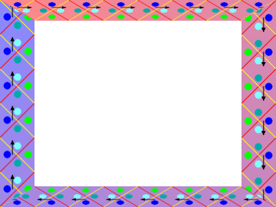
The thickness of the frames at left and right can be different from that at the top and botttom.
call %PICTBAT%mkDispMapRectFrame ^
  w2s_rectf2.png 400 300 50 30

echo rfTotLen=%rfTotLen%
rfTotLen=1400 |
|
call %PICTBAT%mkSqTile ^
  w2s_test_rf2.png %rfTotLen% 50

%IMG7%magick ^
  w2s_rectf2.png ^
  ( +clone -alpha extract -write mpr:ALPH +delete ) ^
  w2s_test_rf2.png ^
  -fx "v.p{r*%%[fx:v.w-1],g*%%[fx:v.h-1]}" ^
  mpr:ALPH ^
  -alpha off -compose CopyOpacity -composite ^
  w2s_d_rf2.png
|
|
In this example, the pieces at the top and bottom have shrunk the image vertically, so circles have been stretched to ellipses. I may enhance the script to compensate for this by also shrinking those pieces horizontally.
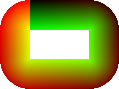
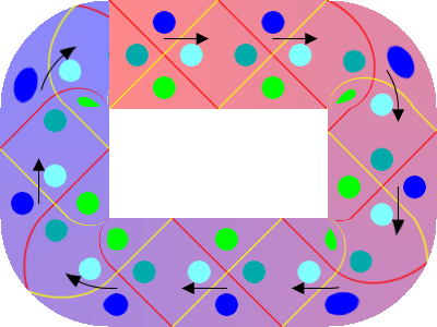
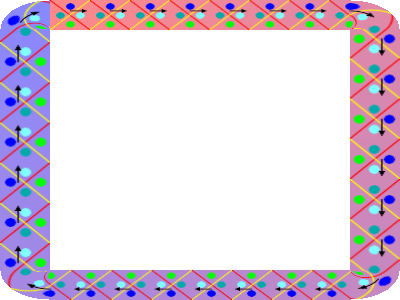
Instead of mitring the corners, we can round them. Each corner is a quarter of an ellipse. The output will contain all of the input pixels, although the pixels at the inside of the corners will shrink to a single pixel.
call %PICTBAT%mkDispMapRectFrameCrvd.bat ^
  w2s_rfc1.png 400 300 100 100

echo rfcTotLen=%rfcTotLen%
rfcTotLen=916 |
|
call %PICTBAT%mkSqTile ^
  w2s_test_rfc1.png %rfcTotLen% 100

%IMG7%magick ^
  w2s_rfc1.png ^
  ( +clone -alpha extract -write mpr:ALPH +delete ) ^
  w2s_test_rfc1.png ^
  -fx "v.p{r*%%[fx:v.w-1],g*%%[fx:v.h-1]}" ^
  mpr:ALPH ^
  -alpha off -compose CopyOpacity -composite ^
  w2s_d_rfc1.png
|
|
As with the mitred corners, we can have two thicknesses for the straight portions. Unlike the mitre method, this doesn't omit input pixels. But we do get different stretching or shrinking in the straight portions. Again, this may be compensated for.
call %PICTBAT%mkDispMapRectFrameCrvd.bat ^
  w2s_rfc2.png 400 300 50 30

echo rfcTotLen=%rfcTotLen%
rfcTotLen=1204 |
|
call %PICTBAT%mkSqTile ^
  w2s_test_rfc2.png %rfcTotLen% 40

%IMG7%magick ^
  w2s_rfc2.png ^
  ( +clone -alpha extract -write mpr:ALPH +delete ) ^
  w2s_test_rfc2.png ^
  -fx "v.p{r*%%[fx:v.w-1],g*%%[fx:v.h-1]}" ^
  mpr:ALPH ^
  -alpha off -compose CopyOpacity -composite ^
  w2s_d_rfc2.png
|
|
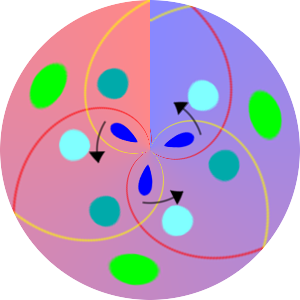
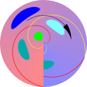
Circular images: tunnel or small-world. (Top or bottom long edge is reduced to single point; green channel gradients are radii of the circle.) Capture entire input, with virtual pixels at corners, or lose pixels in centres of output edges, or do something else.
Or green channel gradient is in a constant direction. "Top" of input is also at "top" of output, but half the output is reversed left-to-right.
Vertical straight lines remain straight. Straight lines at other angles become curves.
Circular images: aspect ratio. Panoramic image 7192x1980 is stretched vertically and rolled up, so each 1980 high column becomes 7192*sqrt(2)/2, and bottom 7192 wide row becomes (mostly outside output image) 2*pi*7192*sqrt(2)/2.
When the input image aspect ratio is π:1 (pi to one), rolling the image into a circle will result in isoscale at y=50% of the input. Small circles at the mid-line of the input remain circles at the same size in the output.
call %PICTBAT%mkSqTile ^ w2s_circ1.png 471 150 |
|
Apply "-distort polar 0" to the image. If this used -virtual-pixel None, output pixels outside the circle would be transparent, but so would pixels where the two sides meet at x=50%.
To get an output of 300x300, we need to resize the input to that size. This will shrink pixels horizontally, only for pixels outside the line of isoscale to be enlarged horizontally. This will lose detail.
The script endless2polar.bat directly distorts an image, using either a -distort or a -fx operation.
|
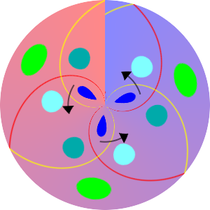
"Tunnel" version, "distort" method. call %PICTBAT%endless2polar ^ w2s_circ1.png w2s_d_pol1.png 300 tunnel ^ . . distort echo e2pTotLen=%e2pTotLen% e2pTotLen=471 The bottom of the result has unchanged orientation. |
|
|
"Small world" version, "distort" method. call %PICTBAT%endless2polar ^ w2s_circ1.png w2s_d_pol2.png 300 smallWorld ^ . . distort echo e2pTotLen=%e2pTotLen% e2pTotLen=471 The top of the result has unchanged orientation. |

|
|
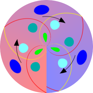
"Tunnel" version, "fx" method. call %PICTBAT%endless2polar ^ w2s_circ1.png w2s_d_pol3.png 300 tunnel ^ . . fx echo e2pTotLen=%e2pTotLen% e2pTotLen=471 The bottom of the result has unchanged orientation. |
|
|
"Small world" version, "fx" method. call %PICTBAT%endless2polar ^ w2s_circ1.png w2s_d_pol4.png 300 smallWorld ^ . . fx echo e2pTotLen=%e2pTotLen% e2pTotLen=471 The top of the result has unchanged orientation. |
|
The fx version gives a less blurry result than the distort version outside the midline, but takes about 50% longer.
What happens if the input aspect ratio isn't π:1? If the image is wider, then more of the image will shrunk horizontally. For example, the centres of the blue circles are at 0.2 of the height, from the top. An apect ratio of 2π:1 would make the top edge of the input (the rim of the output circle) isoscale. To make the blue circles isoscale, we need an aspect ratio of π*(1+0.3/0.5):1 = π*1.6:1.
call %PICTBAT%mkSqTile ^ w2s_circ2.png 754 150 |
|
|
"Small world" version, "fx" method. call %PICTBAT%endless2polar ^ w2s_circ2.png w2s_d_pol5.png 300 smallWorld ^ . . fx echo e2pTotLen=%e2pTotLen% e2pTotLen=471 The top of the result has unchanged orientation. |
|
In the opposite direction, an aspect ratio smaller than π:1 will stretch input horizontally. For example, the centres of the green circles are at 0.8 of the height, from the top. To make those circles isoscale, we need an aspect ratio of π*0.2/0.5:1 = π*0.4:1.
call %PICTBAT%mkSqTile ^ w2s_circ3.png 188 150 |
|
|
"Small world" version, "fx" method. call %PICTBAT%endless2polar ^ w2s_circ3.png w2s_d_pol6.png 300 smallWorld ^ . . fx echo e2pTotLen=%e2pTotLen% e2pTotLen=471 The top of the result has unchanged orientation. |
|
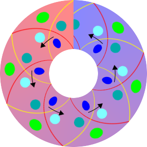
A ring is a generalisation of Circles above. These are circular frames around a circular opening.
If the radii are rMin and rMax where rMin < rMax then:
dropH = rMax - rMin
length = 2 * π * (rMax + rMin) / 2
       = π * (rMax + rMin)
       = π * (rMax + rMax - dropH)
       = 2*π*rMax - π*dropH
rMax = (length + π*dropH) / (2*π)

length / dropH = π * (rMax + rMin) / dropH
For example:
rMax = 150
rMin = 50

dropH = 100
length = π * (150+50) = π * 200 = 628.3

If length=628 and dropH = 100 then
rMax = (628 + π*100) / (2*π) = 149.949.  Correct.
Correcting fx for rMin:
v' = (v - (rMin / rMax)) * rMax / (rMax-rMin)

where
  rMax = w/2
  rMin = (w/2 - dropH)
  rMax - rMin = dropH

so
v' = (v - ((w/2 - dropH) / w/2)) * w/2 / dropH
v' = (v - ((w - 2*dropH) / w)) * w / (w - 2*dropH)
Make a sample input:
set dropH=100 call %PICTBAT%mkSqTile ^ w2s_ring1.png 628 %dropH% |
|
Distort the sample input:
|
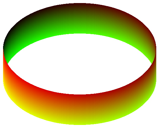
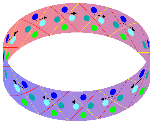
"Tunnel" version, "distort" method. call %PICTBAT%endless2ring ^ w2s_ring1.png w2s_d_ring1.png 300 %dropH% tunnel ^ . distort echo e2rTotLen=%e2rTotLen% e2rTotLen=628 The bottom of the result has unchanged orientation. |

|
|
"Tunnel" version, "fx" method. call %PICTBAT%endless2ring ^ w2s_ring1.png w2s_d_ring2.png 300 %dropH% tunnel ^ . fx echo e2rTotLen=%e2rTotLen% e2rTotLen=628 The bottom of the result has unchanged orientation. |
|
The fx method is clearly sharper than the distort method.
Eg ellipses, rounded rectangles. For use with endless panoramas.
We need to thin the line of the closed shape to ensure that if any single pixel is removed from the line, it is no longer a closed loop, but has exactly two ends. The result will be 8-connected.
set SKEL=^
  -morphology Thinning:-1 Diagonals ^
  -morphology Thinning:-1 Corners ^
  -morphology Thinning:-1 Skeleton:2
We use an ellipse as a sample closed shape.
set margin=10
set radX=250
set radY=150
set dropH=100

set /A WW=(%margin%+%radX%)*2
set /A HH=(%margin%+%radY%)*2+%dropH%
set /A x0=%margin%+%radX%
set /A y0=%margin%
set /A dy=%radY%*2

set /A xRem=%margin%
set /A yRem=%margin%+%radY%

rem goto skipEll

%IMG7%magick ^
  -size %WW%x%HH% xc:Black ^
  +antialias ^
  -stroke White ^
  -draw "path 'M%x0%,%y0% a%radX%,%radY% 0 0,1 0,%dy% a%radX%,%radY% 0 0,1 0,-%dy%'" ^
  %SKEL% ^
  w2s_ell.png

:skipEll
|
w2s_ell.png |
|
We remove one pixel (the first found, or as specified), that is, turn it black, noting its location.
%IMG7%magick ^ w2s_ell.png ^ -fill Black -draw "point %xRem%,%yRem%" ^ w2s_ell2.png |
|
Find the two ends, create gradient along the line. Walk through the pixels in the gradient, adding the removed pixel. By making the start and end at the left-most point, the overlapping curves work in the same way, so the upper part is partly overwritten by the lower part, obscuring it, so the upper part seems to be more distant than the lower part. For input images that are not endless, this also make the join less obvious.
call %PICTBAT%path2ribbon ^
  w2s_ell2.png w2s_ell3.png %dropH% "%x0%,%y0%"

set p2r
p2rDropH=100 p2rNumPixels=1165 p2rOUTFILE=w2s_ell3.png |
|
We use the previous result as an absolute displacement map on a test image. First, we create a test image of the given dimensions.
call %PICTBAT%mkSqTile ^
  w2s_test_ell3.png %p2rNumPixels% %p2rDropH%

%IMG7%magick ^
  w2s_ell3.png ^
  ( +clone -alpha extract -write mpr:ALPH +delete ) ^
  w2s_test_ell3.png ^
  -fx "v.p{r*%%[fx:v.w-1],g*%%[fx:v.h-1]}" ^
  mpr:ALPH ^
  -alpha off -compose CopyOpacity -composite ^
  w2s_d_ell3.png
|
|
The pattern appears to stretch out horizontally towards the left and right sides. This is an illusion, created by our reading of the image as a 2D projection of a 3D object. The illusion could be fixed by a transformation of the red channel, with an adjustment to the path length to restore the scale in the central sections.
For doing the exterior of shapes, we have a gap problem. Maybe solve by expanding the shape with ordinary morphology gradient by (say) 100 pixels, then doing the interior of that shape.
A Möbius strip: use one type of curve at left, and other type at right. Or three overlapping curves.
The distance between successive turns is constant.
See also Spirals.
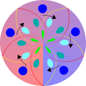
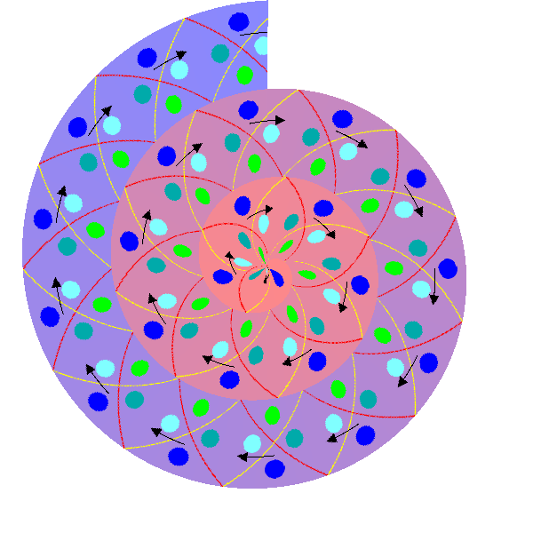
call %PICTBAT%spiralArchi . . 600x600 . 3

echo spiralLen=%spiralLen% spiralThk=%spiralThk%
spiralLen=2380 spiralThk=100
Make the input image:
call %PICTBAT%mkSqTile ^
  w2s_test_archisp.png %spiralLen% %spiralThk%
call %PICTBAT%spiralArchi ^ w2s_test_archisp.png w2s_d_archisp.png ^ 600x600 roll 3 |
|
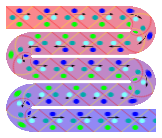
We might also call this a "snake" transformation.
Folded or curved or both.
Curved: parallel drops make overlaps at curves, and alternate straight portions are reversed left-to-right.
call %PICTBAT%mkWindPath ^ abc w2s_windpath1.png |
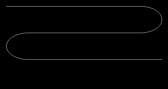
|
call %PICTBAT%path2ribbon ^
  w2s_windpath1.png w2s_windpath2.png

set p2r
p2rDropH=100 p2rNumPixels=1550 p2rOUTFILE=w2s_windpath2.png |
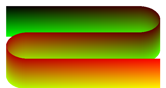
|
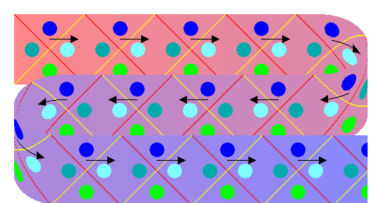
We use the previous result as an absolute displacement map on a test image. First, we create a test image of the given dimensions.
call %PICTBAT%mkSqTile ^
  w2s_test_windpath2.png %p2rNumPixels% %p2rDropH%

%IMG7%magick ^
  w2s_windpath2.png ^
  ( +clone -alpha extract -write mpr:ALPH +delete ) ^
  w2s_test_windpath2.png ^
  -fx "v.p{r*%%[fx:v.w-1],g*%%[fx:v.h-1]}" ^
  mpr:ALPH ^
  -alpha off -compose CopyOpacity -composite ^
  w2s_d_windpath2.png
|
|
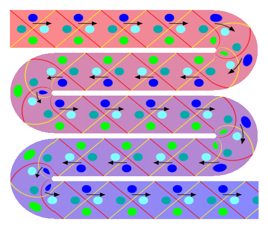
Alternative: at curves we follow the radius, (scaling red channel so average radius is neither stretched nor shrunk) so there is no overlap, and alternate straight portions are rotated by 180°.
call %PICTBAT%mkWindCrvdMap ^
  abc w2s_windcmap1.png

set abc
abc_cumulLen=1998 abc_path=M20 20 H450 a 70,43 0 0 1 0 86 h-360 a 70,43 0 0 0 0 86 H520 abc_stripH=76 |

|
How do we get green channel gradients perpendicular to line? Use gradient of anti-aliased line. When there is sudden change of direction, how do we fill the gap?
In general: attach centre or top or bottom of green channel gradients to the line.
3-D effect: scale red and green channels.
Make a test image to the appropriate dimensions, and distort it.
The output of -composite has the same dimensions as its first input, so we need to resize that to the required dimensions.
call %PICTBAT%mkSqTile ^ w2s_test.png %abc_cumulLen% %abc_stripH% %IMG7%magick ^ w2s_windcmap1.png -set option:MYSIZE %%wx%%h ^ ( +clone -alpha extract -write mpr:ALPH +delete ) ^ ( w2s_test.png -resize "%%[MYSIZE]^!" ) ^ +swap ^ -compose Distort -composite ^ mpr:ALPH ^ -alpha off -compose CopyOpacity -composite ^ w2s_d2.png |
|
The circles at the mid-line of the shape are undistorted, even at the curves. But the result is very blurred.
By using an -fx expression, we avoid the clumsy and blurring -resize:
%IMG7%magick ^
  w2s_windcmap1.png ^
  ( +clone -alpha extract -write mpr:ALPH +delete ) ^
  w2s_test.png ^
  -fx "v.p{r*%%[fx:v.w-1],g*%%[fx:v.h-1]}" ^
  mpr:ALPH ^
  -alpha off -compose CopyOpacity -composite ^
  w2s_d3.png
|
|
The -fx version needs to copy the opacity from the map image.
Given the dimensions of a panoramic image and a required method, suggest suitable parameters for that method: nStrips, etc.
For convenience, .bat scripts are also available in a single zip file. See Zipped BAT files.
rem Make a test image of a tiled square.

rem %1 output file
rem %2 width
rem %3 height

setlocal

set OUTFILE=%1
set WW=%2
set HH=%3

%IMG7%magick ^
  -size %HH%x%HH% xc:None ^
  -fill None ^
  -stroke icc-color(rgb,1,0,0) ^
  -draw "line 0,0,%%[fx:w-1],%%[fx:h-1]" ^
  -stroke icc-color(rgb,1,1,0) ^
  -draw "line %%[fx:w-1],0,0,%%[fx:h-1]" ^
  -stroke None -fill icc-color(rgb,0,0,1) ^
  -draw "translate %%[fx:w*0.5],%%[fx:h*0.2] circle 0,0 0,%%[fx:h*0.1]" ^
  -fill icc-color(rgb,0,0.667,0.667) ^
  -draw "translate %%[fx:w*0.25],%%[fx:h*0.5] circle 0,0 0,%%[fx:h*0.1]" ^
  -fill icc-color(rgb,0.5,1,1) ^
  -draw "translate %%[fx:w*0.75],%%[fx:h*0.5] circle 0,0 0,%%[fx:h*0.1]" ^
  -fill icc-color(rgb,0,1,0) ^
  -draw "translate %%[fx:w*0.5],%%[fx:h*0.8] circle 0,0 0,%%[fx:h*0.1]" ^
  -fill None -stroke icc-color(rgb,0,0,0) ^
  -draw "translate %%[fx:w*0.5],%%[fx:h*0.35] line 0,0 %%[fx:h*0.4],0" ^
  -stroke None -fill icc-color(rgb,0,0,0) ^
  -draw "translate %%[fx:w*0.8],%%[fx:h*0.35] polygon 0,%%[fx:-h*0.05] 0,%%[fx:h*0.05] %%[fx:w*0.1],0" ^
  -colorspace sRGB ^
  -write mpr:SQ +delete ^
  -size %WW%x%HH% ^
  -define gradient:direction=East ^
  gradient:#f88-#88f ^
  tile:mpr:SQ ^
  -compose Over -composite ^
  %OUTFILE%

rem   -background icc-color(rgb,0.6667,0.6667,1) -layers flatten

endlocal
rem Makes a rectangular frame with mitred corners as a displacement map.

rem %1 output file
rem %2 output width
rem %3 output height
rem %4 thickness of left and right pieces
rem %5 thickness of top and bottom pieces
rem ?? Proportion of mitre that will match in the red channel.
rem    0 means the inner edge.
rem    1 means the outer edge.

@setlocal enabledelayedexpansion

@call echoOffSave

set OUTFILE=%1
if "%OUTFILE%"=="." set OUTFILE=

set WW=%2
set HH=%3
set Wlr=%4
set Htb=%5

:: Parameters may be expressions, so evaluate them.

set sFMT=^
WW=%%[fx:%WW%]\n ^
HH=%%[fx:%HH%]\n ^
Wlr=%%[fx:%Wlr%]\n ^
Htb=%%[fx:%Htb%]\n

for /F "usebackq" %%L in (`%IMG7%magick xc: -format "%sFMT%" info:`) do set %%L

:: Makes four pieces, and fits them together, adjusting red values.

:: Each single piece is made horizontally.
:: The vertical side pieces are complete rectangles;
:: the horizontal top and bottom pieces have mitred edges.

:: For now, always match the outer edge.
:: If Wlr NEQ Htb, squares will become rectangles.

set Ltb=%WW%
set Llr=%HH%

set /A Ltot=%Ltb%*2+%Llr%*2

if "%OUTFILE%"=="" goto end

set /A CumulR=%Ltb%
set /A CumulB=%CumulR%+%Llr%
set /A CumulL=%CumulB%+%Ltb%

%IMG7%magick ^
  -size %WW%x%Htb% xc: ^
  -sparse-color Bilinear ^
0,0,#000,^
%%[fx:w-1],0,#f00,^
0,%%[fx:h-1],#0f0,^
%%[fx:w-1],%%[fx:h-1],#ff0 ^
  -channel R -evaluate Multiply %%[fx:%Ltb%/%Ltot%] +channel ^
  ( +clone ^
    +antialias ^
    -fill White -colorize 100 ^
    -fill Black -draw "polygon 0,0 0,%Htb% %Wlr%,%Htb%" ^
    -fill Black -draw "polygon %%[fx:w-1],0 %%[fx:w-1],%%[fx:h-1] %%[fx:w-%Wlr%],%%[fx:h-1]" ^
  ) ^
  -alpha off -compose CopyOpacity -composite ^
  -write mpr:Top ^
  -rotate 180 ^
  -channel R -evaluate Add %%[fx:%CumulB%/%Ltot%*QuantumRange] +channel ^
  -write mpr:Bottom ^
  +delete ^
  -size %HH%x%Wlr% xc: ^
  -sparse-color Bilinear ^
0,0,#000,^
%%[fx:w-1],0,#f00,^
0,%%[fx:h-1],#0f0,^
%%[fx:w-1],%%[fx:h-1],#ff0 ^
  -channel R -evaluate Multiply %%[fx:%Llr%/%Ltot%] +channel ^
  -rotate 90 ^
  ( +clone ^
    -channel R -evaluate Add %%[fx:%CumulR%/%Ltot%*QuantumRange] +channel ^
    -write mpr:Right ^
    +delete ^
  ) ^
  -rotate 180 ^
    -channel R -evaluate Add %%[fx:%CumulL%/%Ltot%*QuantumRange] +channel ^
  -write mpr:Left ^
  +delete ^
  -size %WW%x%HH% xc:None ^
  mpr:Left ^
  -gravity West -compose Over -composite ^
  mpr:Right ^
  -gravity East -compose Over -composite ^
  mpr:Top ^
  -gravity North -compose Over -composite ^
  mpr:Bottom ^
  -gravity South -compose Over -composite ^
  %OUTFILE%

if ERRORLEVEL 1 exit /B 1

:end

call echoRestore

endlocal & set rfTotLen=%Ltot%


exit /B 0
rem Makes a rectangular frame with curved (elliptical) corners as a displacement map.

rem %1 output file
rem %2 output width
rem %3 output height
rem %4 thickness of left and right pieces
rem %5 thickness of top and bottom pieces

@setlocal enabledelayedexpansion

@call echoOffSave

set OUTFILE=%1
if "%OUTFILE%"=="." set OUTFILE=

set WW=%2
set HH=%3
set Wlr=%4
set Htb=%5

:: Parameters may be expressions, so evaluate them.

set sFMT=^
WW=%%[fx:%WW%]\n ^
HH=%%[fx:%HH%]\n ^
Wlr=%%[fx:%Wlr%]\n ^
Htb=%%[fx:%Htb%]\n

for /F "usebackq" %%L in (`%IMG7%magick xc: -format "%sFMT%" info:`) do set %%L

:: Makes four straight pieces and four corners, and fits them together, adjusting red values.

set /A Ltb=%WW%-2*%Wlr%
set /A Llr=%HH%-2*%Htb%

:: Lcrve is approximate
set sFMT=Lcrve=%%[fx:floor (pi*(%Wlr%+%Htb%)/8 + 0.5)]

for /F "usebackq" %%L in (`%IMG7%magick xc: -format "%sFMT%" info:`) do set %%L

set /A Ltot=%Ltb%*2+%Llr%*2+%Lcrve%*4

echo %0: Lcrve=%Lcrve% Ltot=%Ltot%

if "%OUTFILE%"=="" goto end

set /A CumulTR=%Ltb%
set /A CumulR=%Ltb%+%Lcrve%
set /A CumulBR=%CumulR%+%Llr%
set /A CumulB=%CumulBR%+%Lcrve%
set /A CumulBL=%CumulB%+%Ltb%
set /A CumulL=%CumulBL%+%Lcrve%
set /A CumulTL=%CumulL%+%Llr%

set Cumul

:: The prototype corner piece is for bottom-right.

set sFXR=^
  ii = i/%%[fx:w-1]; ^
  jj = j/%%[fx:h-1]; ^
  atan2 (jj, ii) * %%[fx:2/pi * %Lcrve% / %Ltot%]

set sFXG=^
  ii = i/%%[fx:w-1]; ^
  jj = j/%%[fx:h-1]; ^
  1 - hypot (jj, ii)

set sFXA=^
  (g ^< 0) ? 0 : 1

:: Make the prototype corner
:: Make and composite the straight pieces: top, right, bottom and left.
::   Most straight pieces are made 2 pixels overlong, and composited one pixel to left or up,
::   with the curved pieces overwriting the extrat pixels.
::   This avoids duplicating pixels at curved/straight boundaries.
:: Make and composite the curved pieces, clockwise from top-left.

%IMG7%magick ^
  -size %Wlr%x%Htb% xc:Black ^
  -alpha Opaque ^
  -channel R -fx "%sFXR%" ^
  -channel G -fx "%sFXG%" ^
  -channel A -fx "%sFXA%" ^
  +channel ^
  -write mpr:CORN +delete ^
  -size %WW%x%HH% xc:None ^
  ( -size %%[fx:%Ltb%+1]x%Htb% xc:Blue ^
    -sparse-color bilinear "0,0,#000 0,%%[fx:h-1],#0f0 %%[fx:w-1],%%[fx:h-1],#ff0" ^
    -channel R -evaluate Multiply %%[fx:(%Ltb%+1)/%Ltot%] +channel ^
  ) ^
  -geometry +%%[fx:%Wlr%]+0 ^
  -compose Over -composite ^
  ( -size %%[fx:%Llr%+2]x%Wlr% xc:Blue ^
    -sparse-color bilinear "0,0,#000 0,%%[fx:h-1],#0f0 %%[fx:w-1],%%[fx:h-1],#ff0" ^
    -channel R -evaluate Multiply %%[fx:(%Llr%+0)/%Ltot%] +channel ^
    -channel R -evaluate Add %%[fx:%CumulR%/%Ltot%*QuantumRange] +channel ^
    -rotate 90 ^
  ) ^
  -geometry +%%[fx:%WW%-%Wlr%]+%%[fx:%Htb%-1] ^
  -compose Over -composite ^
  ( -size %%[fx:%Ltb%+2]x%Htb% xc:Blue ^
    -sparse-color bilinear "0,0,#000 0,%%[fx:h-1],#0f0 %%[fx:w-1],%%[fx:h-1],#ff0" ^
    -channel R -evaluate Multiply %%[fx:(%Ltb%+0)/%Ltot%] +channel ^
    -channel R -evaluate Add %%[fx:%CumulB%/%Ltot%*QuantumRange] +channel ^
    -rotate 180 ^
  ) ^
  -geometry +%%[fx:%Wlr%-1]+%%[fx:%HH%-%Htb%] ^
  -compose Over -composite ^
  ( -size %%[fx:%Llr%+2]x%Wlr% xc:Blue ^
    -sparse-color bilinear "0,0,#000 0,%%[fx:h-1],#0f0 %%[fx:w-1],%%[fx:h-1],#ff0" ^
    -channel R -evaluate Multiply %%[fx:(%Llr%+0)/%Ltot%] +channel ^
    -channel R -evaluate Add %%[fx:%CumulL%/%Ltot%*QuantumRange] +channel ^
    -rotate 270 ^
  ) ^
  -geometry +0+%%[fx:%Htb%-1] ^
  -compose Over -composite ^
  ( mpr:CORN -flip -flop ^
    -channel R -evaluate Add %%[fx:%CumulTL%/%Ltot%*QuantumRange] +channel ^
  ) ^
  -geometry +0+0 ^
  -compose Over -composite ^
  ( mpr:CORN -flip ^
    -channel R -function Polynomial "-1,%%[fx:%Lcrve%/%Ltot% + %CumulTR%/%Ltot%]" +channel ^
  ) ^
  -geometry +%%[fx:%WW%-%Wlr%]+0 ^
  -compose Over -composite ^
  ( mpr:CORN ^
    -channel R -evaluate Add %%[fx:%CumulBR%/%Ltot%*QuantumRange] +channel ^
  ) ^
  -geometry +%%[fx:%WW%-%Wlr%]+%%[fx:%HH%-%Htb%] ^
  -compose Over -composite ^
  ( mpr:CORN -flop ^
    -channel R -function Polynomial "-1,%%[fx:%Lcrve%/%Ltot% + %CumulBL%/%Ltot%]" +channel ^
  ) ^
  -geometry +0+%%[fx:%HH%-%Htb%] ^
  -compose Over -composite ^
  -define quantum:format=floating-point -depth 32 ^
  %OUTFILE%

if ERRORLEVEL 1 exit /B 1

:end

call echoRestore

endlocal & set rfcTotLen=%Ltot%
rem From an endless panorama,
rem make a polar version.

rem %1 input endless panorama
rem %2 output polar image
rem %3 output width and height [default: input width]
rem %4 version: "tunnel" [default] or "smallWorld"
rem %5 circle type: whether input is "inscribed" [default] within output or "circumscribed" to corners of output.
rem %6 "trans" [default] or "noTrans": whether to make pixels outside the circle transparent.
rem %7 method: "distort" [default] or "fx".

@rem Also uses:
@rem
@rem  e2pColSpIn eg "-colorspace RGB"
@rem  e2pColSpOut eg "-colorspace sRGB"
@rem

@if "%2"=="" findstr /B "rem @rem" %~f0 & exit /B 1

@setlocal enabledelayedexpansion

@call echoOffSave

set INFILE=%1
set OUTFILE=%2
if "%OUTFILE%"=="." set OUTFILE=

set OutDim=%3
if "%OutDim%"=="." set OutDim=
if "%OutDim%"=="" set OutDim=%%%w

echo %0: OutDim=%OutDim%

set Version=%~4
if "%Version%"=="." set Version=
if "%Version%"=="" set Version=tunnel

set CircType=%~5
if "%CircType%"=="." set CircType=
if "%CircType%"=="" set CircType=inscribed

set DoTrans=%~6
if "%DoTrans%"=="." set DoTrans=
if "%DoTrans%"=="" set DoTrans=trans

set Method=%~7
if "%Method%"=="." set Method=
if "%Method%"=="" set Method=distort

if "%OUTFILE%"=="" goto end

if /I "%Version%"=="tunnel" (
  set DoRot=
) else if /I "%Version%"=="smallWorld" (
  set DoRot=-rotate 180
) else (
  echo %0: Bad Version [%Version%]
  exit /B 1
)

if /I %CircType%==inscribed (
  set PolNum=0
  set ScaleRho=2
) else if /I %CircType%==circumscribed (
  set PolNum=-1
  set ScaleRho=sqrt^(2^)
) else (
  echo %0: Bad CircType [%CircType%]
  exit /B 1
)

set sTrans=
if /I "%DoTrans%"=="trans" (
  set sTrans=^
    ^( +clone -fill Black -colorize 100 ^
       -fill White ^
       -draw "translate %%[fx:(w-1)/2],%%[fx:(h-1)/2] circle 0,0,%%[fx:(w-1)/2],0" ^
    ^) ^
    -alpha off -compose CopyOpacity -composite

) else if /I "%DoTrans%"=="noTtrans" (
  set sTrans=
) else (
  echo %0: Bad DoTrans [%DoTrans%]
  exit /B 1
)

if /I not "%Method%"=="distort" if /I not "%Method%"=="fx" (
  echo %0: Bad Method [%Method%]
  exit /B 1
)


if /I "%Method%"=="fx" goto DoFx

%IMG7%magick ^
  %INFILE% ^
  %e2pColSpIn% ^
  %DoRot% ^
  -resize "%OutDim%x%OutDim%^!" ^
  -virtual-pixel Edge -distort polar %PolNum% ^
  %DoRot% ^
  %sTrans% ^
  %Sharpen% ^
  %e2pColSpOut% ^
  %OUTFILE%

if ERRORLEVEL 1 exit /B 1

goto end


:DoFx

:: atan2() returns -pi to +pi

set sFX=^
  ii=(i/%%[fx:u.w-1])-0.5; ^
  jj=(j/%%[fx:u.h-1])-0.5; ^
  xx=atan2(ii,jj)/%%[fx:2*pi] + 0.5; ^
  yy=hypot(ii,jj) * %%[fx:%ScaleRho%]; ^
  v.p{xx * %%[fx:v.w-1], yy * %%[fx:v.h-1]}

%IMG7%magick ^
  ( %INFILE% ^
    %e2pColSpIn% ^
    %DoRot% ^
  ) ^
  -size %OutDim%x%OutDim% xc: ^
  +swap ^
  -fx "%sFX%" ^
  %DoRot% ^
  %sTrans% ^
  %Sharpen% ^
  %e2pColSpOut% ^
  %OUTFILE%

if ERRORLEVEL 1 exit /B 1

:end

for /F "usebackq" %%L in (`%IMG7%magick xc: ^
  -format "TotLen=%%[fx:floor (pi*%OutDim%/2 + 0.5)]\n" ^
  info:`) do set %%L

call echoRestore

@endlocal & set e2pTotLen=%TotLen%
rem From an endless panorama,
rem make a ring version.

rem %1 input endless panorama
rem %2 output polar image
rem %3 output width and height [default: input width]
rem %4 drop height (ring thickness) [default: input height]
rem %5 version: "tunnel" [default] or "smallWorld"
rem %6 "trans" [default] or "noTrans": whether to make pixels outside the circle transparent.
rem %7 method: "distort" [default] or "fx".

@rem Also uses:
@rem
@rem  e2rColSpIn eg "-colorspace RGB"
@rem  e2rColSpOut eg "-colorspace sRGB"
@rem

@if "%2"=="" findstr /B "rem @rem" %~f0 & exit /B 1

@setlocal enabledelayedexpansion

@call echoOffSave

set INFILE=%1
set OUTFILE=%2
if "%OUTFILE%"=="." set OUTFILE=

set OutDim=%3
if "%OutDim%"=="." set OutDim=
if "%OutDim%"=="" set OutDim=%%%w

set dropH=%4
if "%dropH%"=="." set dropH=
if "%dropH%"=="" set dropH=100

set Version=%~5
if "%Version%"=="." set Version=
if "%Version%"=="" set Version=tunnel

set DoTrans=%~6
if "%DoTrans%"=="." set DoTrans=
if "%DoTrans%"=="" set DoTrans=trans

set Method=%~7
if "%Method%"=="." set Method=
if "%Method%"=="" set Method=distort

if "%OUTFILE%"=="" goto end

if /I "%Version%"=="tunnel" (
  set DoRot=
) else if /I "%Version%"=="smallWorld" (
  set DoRot=-rotate 180
) else (
  echo %0: Bad Version [%Version%]
  exit /B 1
)

set ScaleRho=2

set sTrans=
if /I "%DoTrans%"=="trans" (
  set sTrans=^
    ^( +clone -fill Black -colorize 100 ^
       -fill White ^
       -draw "translate %%[fx:(w-1)/2],%%[fx:(h-1)/2] circle 0,0,%%[fx:(w-1)/2],0" ^
       -fill Black ^
       -draw "translate %%[fx:(w-1)/2],%%[fx:(h-1)/2] circle 0,0,%%[fx:(w-1)/2-%dropH%],0" ^
    ^) ^
    -alpha off -compose CopyOpacity -composite

) else if /I "%DoTrans%"=="noTtrans" (
  set sTrans=
) else (
  echo %0: Bad DoTrans [%DoTrans%]
  exit /B 1
)

if /I not "%Method%"=="distort" if /I not "%Method%"=="fx" (
  echo %0: Bad Method [%Method%]
  exit /B 1
)


if /I "%Method%"=="fx" goto DoFx

%IMG7%magick ^
  %INFILE% ^
  %e2rColSpIn% ^
  %DoRot% ^
  -resize "%OutDim%x%OutDim%^!" ^
  -virtual-pixel Edge -distort polar "%%[fx:w/2],%%[fx:w/2-%dropH%-1]" ^
  %DoRot% ^
  %sTrans% ^
  %Sharpen% ^
  %e2rColSpOut% ^
  %OUTFILE%

if ERRORLEVEL 1 exit /B 1

goto end


:DoFx

:: atan2() returns -pi to +pi

set sFX=^
  ii=(i/%%[fx:u.w-1])-0.5; ^
  jj=(j/%%[fx:u.h-1])-0.5; ^
  xx=atan2(ii,jj)/%%[fx:2*pi] + 0.5; ^
  yy=hypot(ii,jj) * %%[fx:%ScaleRho%]; ^
  yy = (yy - %%[fx:(w-2*%dropH%) / w]) * %%[fx:w / 2 / %dropH%]; ^
  v.p{xx * %%[fx:v.w-1], yy * %%[fx:v.h-1]}

%IMG7%magick ^
  ( %INFILE% ^
    %e2rColSpIn% ^
    %DoRot% ^
  ) ^
  -size %OutDim%x%OutDim% xc: ^
  +swap ^
  -fx "%sFX%" ^
  %DoRot% ^
  %sTrans% ^
  %Sharpen% ^
  %e2rColSpOut% ^
  %OUTFILE%

if ERRORLEVEL 1 exit /B 1

:end

for /F "usebackq" %%L in (`%IMG7%magick xc: ^
  -format "TotLen=%%[fx:floor (pi*(%OutDim%-%dropH%) + 0.5)]\n" ^
  info:`) do set %%L

call echoRestore

@endlocal & set e2rTotLen=%TotLen%
rem %1 input image, a white 8-connected line with exactly two ends,
rem   on black or transparent-black background.
rem %2 output image
rem %3 drop height.
rem %4 optional coordinate pair to be added to the line. Quoted, with comma, eg "260,10".

@if "%1"=="" findstr /B "rem @rem" %~f0 & exit /B 1

@setlocal enabledelayedexpansion

@call echoOffSave

call %PICTBAT%setInOut %1 p2r

set OUTFILE=%2
if "%OUTFILE%"=="." set OUTFILE=

set DropH=%3
if "%DropH%"=="." set DropH=
if "%DropH%"=="" set DropH=100

set ExtraCoord=%~4
if "%ExtraCoord%"=="." set ExtraCoord=

if not "%5"=="" (
  echo %0: Seem to have 5 parameters. [%5]
  exit /B 1
)

set ExtraX=
set ExtraY=
if not "%ExtraCoord%"=="" (
  call parseCommaList "%ExtraCoord%" p2r_num p2r_vals

  if not "!p2r_num!"=="2" (
    echo %0: Bad coordinate pair [!p2r_num!]
    exit /B 1
  )

  set ExtraX=!p2r_vals[0]!
  set ExtraY=!p2r_vals[1]!

  echo Extra=!ExtraX!,!ExtraY!
)


set N=0
for /F "usebackq tokens=1,2 delims=," %%A in (`%IMG7%magick ^
  %INFILE% ^
  -morphology HMT LineEnds ^
  -transparent Black ^
  sparse-color: ^| tr " " "\n"`) do (
  set X!N!=%%A
  set Y!N!=%%B
  set /A N+=1
)

if not %N%==2 (
  echo %0: Doesn't have two ends. N==%N%.
  exit /B 1
)

echo %0: Ends are (%X0%,%Y0%) and (%X1%,%Y1%).

:: Draw a gradient along the line.
:: Set the red channel to 0, 1, 2...
:: At the end, divide red channel by its maximum.

set ScrFile=%TEMP%\p2r_scr.scr

(
  echo -size 1x%DropH% gradient:#000-#ff0 -write mpr:VERT +delete
  echo %INFILE% -set colorspace sRGB
  echo -transparent Black
  echo -set option:HH %%h
) >%ScrFile%

set DoResize=0

set N=0
(
  if not "%ExtraX%"=="" (
    echo ^( mpr:VERT
    echo    -channel R -evaluate set !N! +channel
    if %DoResize%==1 (
      echo    -resize 1x%%[fx:%DropH%*%ExtraY%/%%[HH]]!
    )
    echo    -set page   +%ExtraX%+%ExtraY% ^)
    set /A N+=1
  )

  for /F "usebackq tokens=1-2 delims=," %%A in (`%IM7DEV%magick ^
    %INFILE% ^
    -negate ^
    -evaluate Subtract 1 -clamp -evaluate Add 1 ^
    -colorspace sRGB ^
    -process ^
      "darkestpntpnt s %X0%,%Y0% e %X1%,%Y1% t 0.5 print" ^
    -channel G -separate -auto-level +channel ^
    NULL: 2^>^&1`) do (
    echo ^( mpr:VERT
    echo    -channel R -evaluate set !N! +channel
    if %DoResize%==1 (
      echo    -resize 1x%%[fx:%DropH%*%%B/%%[HH]]!
    )
    echo    -set page +%%A+%%B ^)
    set /A N+=1
  )
) >>%ScrFile%

:: The resizing could be done like this:
::
::   -virtual-pixel None -filter point -distort SRT 0,0,1,0.55,0
::   -channel RGB -auto-level +channel

echo %0: There are %N% pixels on the line.

if "%OUTFILE%"=="" goto end

(
  echo -background None
  echo -layers flatten
  echo -channel R -evaluate divide %%[fx:maxima.r] +channel
  echo -define quantum:format=floating-point -depth 32
  echo -write %OUTFILE%
  echo -exit
) >>%ScrFile%

if not "%OUTFILE%"=="" (
  echo %0: Running script %ScrFile%
  %IMG7%magick -script %ScrFile%

  if ERRORLEVEL 1 exit /B 1
)

:end

echo %0: end: outfile=%OUTFILE%

call echoRestore

endlocal & set p2rOUTFILE=%OUTFILE%& set p2rNumPixels=%N%& set p2rDropH=%DropH%
rem Make a winding path,
rem white on black background,
rem suitable for input to path2ribbon.bat.

rem %1 prefix for environment variables.
rem %2 optional output image file [default: no output image]

setlocal enabledelayedexpansion

set ProjPref=%1
if "%ProjPref%"=="." set ProjPref=
if "%ProjPref%"=="" set ProjPref=mwp

set OUTFILE=%2
if "%OUTFILE%"=="." set OUTFILE=

set margin=20
set stripW=500
set stripH=76
set nStrips=3
set stripGap=10
set radX=70
set /A radY=(%stripH%+%stripGap%)/2

set /A nCurves=%nStrips%-1
set /A nCurvesL=%nCurves%/2
set /A nCurvesR=%nCurves%-%nCurvesL%

set /A nStripsCol2=%nStrips%/2
set /A nStripsCol1=%nStrips%-%nStripsCol2%

set LastIsCol1=1
if %nStripsCol1%==%nStripsCol2% set LastIsCol1=0

set /A WW=%stripW%+2*%margin%
set /A HH=%margin%+%nStrips%*%stripH%+(%nStrips%-1)*%stripGap%+%margin%

set /A stripWtop=%stripW%-%radX%

rem Make a SVG-style winding path.

set DrawCol1=1
set DrawCol2=1

set y0=%margin%

set PTH=
:loop

:: Left-to-right horizontal line.

set /A x0=%margin%+%radX%
if %DrawCol1%==1 set x0=%margin%
set /A x1=%margin%+%stripW%-%radX%
if %DrawCol1%==%nStripsCol1% if %LastIsCol1%==1 set /A x1=%WW%-%margin%

if %DrawCol1%==1 (
  set PTH=M%x0% %y0%
)
set PTH=%PTH% H%x1%

if %DrawCol2% GTR %nStripsCol2% goto endPath

set /A DrawCol1+=1

:: Curve at right side.

set /A dy=%stripH%+%stripGap%

set PTH=%PTH% a %radX%,%radY% 0 0 1 0 %dy%

set /A y0+=%dy%

:: Right-to-left horizontal line.

set /A dx=%stripW%-2*%radX%
if %DrawCol2% GEQ %nStripsCol2% if %LastIsCol1%==0 set /A dx+=%radX%
set PTH=%PTH% h-%dx%

if %DrawCol1% GTR %nStripsCol1% goto endPath

:: Curve at left side.

set PTH=%PTH% a %radX%,%radY% 0 0 0 0 %dy%

set /A DrawCol2+=1

if %DrawCol1% LEQ %nStripsCol1% goto loop

:endPath

echo PTH=%PTH%

rem We can supersample with:
rem   -draw "scale 2.0,2.0 path '%PTH%'"
rem If we want gradients, omit antialias and morphologies.

if not "%OUTFILE%"=="" (

  set MORPH=^
    -morphology Thinning:-1 Diagonals ^
    -morphology Thinning:-1 Corners ^
    -morphology Thinning:-1 Skeleton:2

  %IMG7%magick ^
    -size %WW%x%HH% xc:Black ^
    +antialias ^
    -fill None -stroke White -draw "path '%PTH%'" ^
    !MORPH! ^
    %OUTFILE%

  if ERRORLEVEL 1 exit /B 1

)

rem call %PICTBAT%path2ribbon x.png

endlocal & set %ProjPref%_path=%PTH%
rem Make a displacement map following a curved path, with semi-circular ends.

rem %1 prefix for environment variables.
rem %2 output image file

setlocal enabledelayedexpansion

set ProjPref=%1
if "%ProjPref%"=="." set ProjPref=
if "%ProjPref%"=="" set ProjPref=mwcm

set OUTFILE=%2
if "%OUTFILE%"=="." set OUTFILE=

set margin=20
set stripW=500
set stripH=76
set nStrips=5
set stripGap=10
set radX=90
set /A radY=%stripH%+%stripGap%/2

:: Shld check that stripW GTR radX

set /A nCurves=%nStrips%-1
set /A nCurvesL=%nCurves%/2
set /A nCurvesR=%nCurves%-%nCurvesL%

set /A nStripsCol2=%nStrips%/2
set /A nStripsCol1=%nStrips%-%nStripsCol2%

set LastIsCol1=1
if %nStripsCol1%==%nStripsCol2% set LastIsCol1=0

set /A WW=%stripW%+2*%margin%
set /A HH=%margin%+%nStrips%*%stripH%+(%nStrips%-1)*%stripGap%+%margin%

set /A stripWtop=%stripW%-%radX%

set CrveFile=%TEMP%\%ProjPref%_mwcm_crve.miff
set ScrFile=%TEMP%\%ProjPref%_mwcm_scr.scr

:: Build an image for the curved portions.

set lenCurve=floor(pi*(%radX%+%stripGap%)/2+0.5)

for /F "usebackq" %%L in (`%IMG7%magick ^
  xc:
  -format "lenCurve=%%[fx:%lenCurve%]" ^
  info:`) do set %%L

set /A totLen=%nStrips%*(%stripW%-2*%radX%)+2*%radX%+%nCurves%*%lenCurve%

echo %0: lenCurve=%lenCurve%
echo %0: totLen=%totLen%

set /A WWC=%radX%
set /A HHC=2*%radY%+%stripGap%
set /A HHC=2*%stripH%+%stripGap%

:: The red channel is scaled by CrveFact, the fraction of the total length of the path.

set sFxR=^
  CrveFact = %%[fx:%lenCurve%/%totLen%]; ^
  halfh = %%[fx:(h-1)/2]; ^
  ii = i/(w-1); ^
  jj = (j-halfh)/halfh; ^
  ang = 1 - atan2(ii,jj) / pi; ^
  ang * CrveFact

set sFxG=^
  ry = %%[fx:%stripGap%/2]; ^
  rx = %%[fx:%stripGap%/2 * %radX% / %radY%]; ^
  rrfact = %%[fx:%radY% / (%radY% - %stripGap%/2)]; ^
  halfh = %%[fx:(h-1)/2]; ^
  ii = i/(w-1); ^
  jj = (j-halfh)/halfh; ^
  iiX = (i-rx)*(%radX%-rx)/(%radX%-1); ^
  jjX = (j-rx-halfh)/halfh; ^
  rr = (1 - hypot(ii,jj)) * rrfact; ^
  rr

set sFxA=^
  (g ^> 1 ^|^| g ^< 0) ? 0 : 1


%IMG7%magick ^
  -size %WWC%x%HHC% xc:None ^
  -channel R -fx "%sFxR%" +channel ^
  -channel G -fx "%sFxG%" +channel ^
  -channel A -fx "%sFxA%" +channel ^
  -define quantum:format=floating-point -depth 32 ^
  %CrveFile%

if ERRORLEVEL 1 exit /B 1

:: At each placement of the curve, maybe flip it left-to-right, and add something to the red channel.

:: Assemble the pieces by writing and executing an IM script file.

(
  echo -size %WW%x%HH% xc:None
) >%ScrFile%

set DrawCol1=1
set DrawCol2=1

set y0=%margin%

set cumulLen=0

:loop

:: Left-to-right horizontal line.
:: To get continuity of red channel,
:: make this one pixel wider than needed,
:: and overwrite that with the following curve.

set /A x0=%margin%+%radX%
if %DrawCol1%==1 set x0=%margin%
set /A x1=%margin%+%stripW%-%radX%
if %DrawCol1%==%nStripsCol1% if %LastIsCol1%==1 set /A x1=%WW%-%margin%

(
  echo ^( -size %%[fx:%x1%-%x0%+1]x%stripH% xc:Blue
  echo    -sparse-color bilinear "0,0,#000 0,%%[fx:h-1],#0f0 %%[fx:w-1],%%[fx:h-1],#ff0"
  echo    -channel R -evaluate Multiply %%[fx:^(%x1%-%x0%^)/%totLen%] +channel

  if not %cumulLen%==0 (
    echo    -channel R -evaluate Add %%[fx:%cumulLen%/%totLen%*QuantumRange] +channel
  )
  echo ^)
  echo -geometry +%x0%+%y0%
  echo -compose Over -composite
) >>%ScrFile%

if %DrawCol2% GTR %nStripsCol2% goto endPath

set /A dy=%stripH%+%stripGap%

set /A DrawCol1+=1

set /A cumulLen+=%x1%-%x0%

:: Curve at right side.

(
  echo ^( mpr:CRVE
  echo    -channel R -evaluate Add %%[fx:%cumulLen%/%totLen%*QuantumRange] +channel
  echo ^)
  echo -geometry +%x1%+%y0%
  echo -compose Over -composite
) >>%ScrFile%

set /A cumulLen+=%lenCurve%

set /A y0+=%stripGap%+%stripH%

:: Right-to-left horizontal line.

set /A x0=%margin%+%radX%
if %DrawCol2% GEQ %nStripsCol2% if %LastIsCol1%==0 set /A x0-=%radX%

:: BUG: shld adjust 1 pixel only if not last.
(
  echo ^( -size %%[fx:%x1%-%x0%+1]x%stripH% xc:Blue
  echo    -sparse-color bilinear "0,0,#ff0 0,%%[fx:h-1],#f00 %%[fx:w-1],%%[fx:h-1],#000"
  echo    -channel R -evaluate Multiply %%[fx:^(%x1%-%x0%^)/%totLen%] +channel
  echo    -channel R -evaluate Add %%[fx:%cumulLen%/%totLen%*QuantumRange] +channel
  echo ^)
  echo -geometry +%%[fx:%x0%-1]+%y0%
  echo -compose Over -composite
) >>%ScrFile%

set /A cumulLen+=%x1%-%x0%

if %DrawCol1% GTR %nStripsCol1% goto endPath

:: Curve at left side.

(
  echo ^( mpr:CRVE -flop
  echo    -channel R -evaluate Add %%[fx:%cumulLen%/%totLen%*QuantumRange] +channel
  echo    -channel G -negate +channel
  echo ^)
  echo -geometry +%margin%+%y0%
  echo -compose Over -composite
) >>%ScrFile%

set /A cumulLen+=%lenCurve%

set /A DrawCol2+=1

set /A y0+=%stripGap%+%stripH%

if %DrawCol1% LEQ %nStripsCol1% goto loop

:endPath

echo %0: cumulLen=%cumulLen%

(
  echo -write %OUTFILE%
  echo -exit
) >>%ScrFile%

type %ScrFile%


%IMG7%magick %CrveFile% -write mpr:CRVE +delete -script %ScrFile%

if ERRORLEVEL 1 exit /B 1


endlocal & set %ProjPref%_stripH=%stripH%& set %ProjPref%_cumulLen=%cumulLen%
rem Archimedean spiral
rem https://www.mathsisfun.com/geometry/ellipse-perimeter.html

rem  r = a * theta
rem  len = a/2 * [theta * sqrt(1+theta^2) + ln (theta + sqrt(1+theta^2))]

rem Make a Archimedean spiral.
rem %1 input image to be rolled into a spiral.
rem %2 output image file
rem %3 output size WxH
rem %4 output type: radial [default], length, line, dispmap, roll
rem %5 REVS
rem   REVS is the number of complete revolutions
rem   the dividing line makes
rem   from the centre to the edge of the enclosing circle (or ellipse).
@rem
@rem Returns environment variables spiralLen and spiralThk.
@rem

@rem Also need: whether to cut off at north.

@if "%1"=="" findstr /B "rem @rem" %~f0 & exit /B 1

@setlocal enabledelayedexpansion

rem @call echoOffSave

set INFILE=%1
if "%INFILE%"=="." set INFILE=

set OUTFILE=%2
if "%OUTFILE%"=="." set OUTFILE=

set Size=%3
if "%Size%"=="." set Size=

set OutType=%4
if "%OutType%"=="." set OutType=
if "%OutType%"=="" set OutType=radial

set REVS=%~5
if "%REVS%"=="." set REVS=
if "%REVS%"=="" set REVS=4

call parseXxY2i 300 300 spiralArchi %Size%

set WW=%spiralArchi_X%
set HH=%spiralArchi_Y%

set MAPFILE=%TEMP%\samap.png

set LenFact=(%REVS%-0.5)/%REVS%

set NeedRadial=0
set NeedLength=0
set DispImg=0
set sLine=
if /I %OutType%==radial (
  set NeedRadial=1
) else if /I %OutType%==length (
  set NeedLength=1
) else if /I %OutType%==line (
  set NeedRadial=1
  set sLine=-edge 1
) else if /I %OutType%==dispmap (
  set DispImg=1
) else if /I %OutType%==roll (
  set DispImg=1
) else (
  echo %0: Bad OutType [%OutType%]
  exit /B 1
)


rem What is the calculated length at REVS * 2pi radians?
rem We assume the image is square.

set sFXcalc= ^
  thth = %REVS% * 2 * pi; ^
  thhpy = hypot (1, thth); ^
  pixelsPerRad = ((%HH%-1)/2) / thth; ^
  len = %LenFact% * pixelsPerRad/2 * (thth * thhpy + ln (thth + thhpy)); ^
  floor (len+0.5)

for /F "usebackq" %%L in (`%IMG7%magick ^
  xc: ^
  -precision 15 ^
  -format "calcLen=%%[fx:%sFXcalc%]\ncalcThk=%%[fx:floor(%WW%/%REVS%/2+0.5)]" ^
  info:`) do set %%L

echo %0: calcLen = %calcLen%  calcThk=%calcThk%

if "%calcLen%"=="" (
  echo %0: Failed to calculate calcLen.
  exit /B 1
)

set VirtPix=
if /I %OutType%==dispmap (
  %IMG7%magick ^
  -size %calcLen%x%calcThk% ^
  -define gradient:direction=East ^
  gradient:Black-White ^
  -define gradient:direction=North ^
  gradient:White-Black ^
  xc:Black ^
  -combine ^
  %MAPFILE%
) else if /I %OutType%==roll (
  set MAPFILE=%INFILE%
  set VirtPix=-virtual-pixel None
) else (
  set MAPFILE=
)

set sFX= ^
  twopi = %%[fx:2*pi]; ^
  twoOverWm = %%[fx:2/(w-1)]; ^
  twoOverHm = %%[fx:2/(h-1)]; ^
  xx = twoOverWm*i - 1; ^
  yy = twoOverHm*j - 1; ^
  rho = hypot (xx, yy); ^
  theta = atan2 (xx, yy) / twopi + 0.5; ^
  rr = rho*%REVS% + theta;

:: We use "goto" instead of "if (...)" to avoid needing to escape parentheses.
if %NeedRadial%==0 goto skipRadial

set sFX=%sFX% rr - floor (rr)

:skipRadial

if %NeedLength%==0 goto skipLength

set sFX=%sFX% ^
  thth = (1 -theta + floor (rr)) * twopi; ^
  thhpy = hypot (1, thth); ^
  ppr = %%[fx:%LenFact% * ((h-1)/2) / (4*pi * %REVS%)]; ^
  len = ppr * (thth * thhpy + ln (thth + thhpy)); ^
  len/%calcLen%

:skipLength

if %DispImg%==0 goto skipDispImg

set sFX=%sFX% ^
  mapY = 1 - rr + floor (rr); ^
  thth = (1 -theta + floor (rr)) * twopi; ^
  thhpy = hypot (1, thth); ^
  ppr = %%[fx:%LenFact% * ((h-1)/2) / (4*pi * %REVS%)]; ^
  len = ppr * (thth * thhpy + ln (thth + thhpy)); ^
  mapX = len/%calcLen%; ^
  v.p{floor(mapX*%%[fx:v.w-1]), floor(mapY*%%[fx:v.h-1])}

:skipDispImg

rem ppr is pixelsPerRad/2.

rem -1 <= xx,yy <= +1
rem So 0 <= rho <= 1.414; rho=1.0 at centre of each edge.
rem theta is zero and one at north, increasing anticlockwise
rem 0 <= theta <= 1

rem Assuming image is square of radius "rad":
rem   pixelsPerRad = rad / (2pi * REVS)

if "%OUTFILE%"=="" goto skipWrite

%IMG7%magick ^
  -size %spiralArchi_X%x%spiralArchi_Y% xc:White ^
  %MAPFILE% ^
  %VirtPix% ^
  -fx "%sFX%" ^
  %sLine% ^
  -define quantum:format=floating-point -depth 32 ^
  %OUTFILE%

:skipWrite

call echoRestore

endlocal & set spiralLen=%calcLen%& set spiralThk=%calcThk%
All images on this page were created by the commands shown, using:
%IMG7%magick -version
Version: ImageMagick 7.1.1-20 Q16-HDRI x86 98bb1d4:20231008 https://imagemagick.org
Copyright: (C) 1999 ImageMagick Studio LLC
License: https://imagemagick.org/script/license.php
Features: Cipher DPC HDRI OpenCL OpenMP(2.0)
Delegates (built-in): bzlib cairo freetype gslib heic jng jp2 jpeg jxl lcms lqr lzma openexr pangocairo png ps raqm raw rsvg tiff webp xml zip zlib
Compiler: Visual Studio 2022 (193532217)
To improve internet download speeds, some images may have been automatically converted (by ImageMagick, of course) from PNG or TIFF or MIFF to JPG.
Source file for this web page is wide2sq.h1. To re-create this web page, run "procH1 wide2sq".
This page, including the images, is my copyright. Anyone is permitted to use or adapt any of the code, scripts or images for any purpose, including commercial use.
Anyone is permitted to re-publish this page, but only for non-commercial use.
Anyone is permitted to link to this page, including for commercial use.
Page version v1.0 18-August-2024.
Page created 20-Aug-2024 12:58:15.
Copyright © 2024 Alan Gibson.