snibgo's ImageMagick pages
Scale, rotate and translate in 3D
A simple but effective method.
Three-dimensional transformations can be complex, especially if we want realistic lighting. However, some 3D can be performed simply and quickly.
On this page, we apply perspective transformations (scale, rotate and translate) in three dimensions.
Software shown here accumulates an arbitrary series of scales, rotations and translations into a single 4x4 transformation matrix; applies that matrix to a list of x, y and z coordinates (possibly also applying perspective); and applies the transformation to an image.
This page uses a process module. See
Process modules: scale, rotate and translate in 3d for the source code.
The x- and y-axes are as usual for ImageMagick: x increases from left to right; y increases from top to bottom.
The z-axis increases from the screen towards the viewer.
Positive rotation around an axis is in the clockwise direction, when viewed along the axis towards the origin (0,0,0). Hence the usual IM -rotate 5 is a +5 degree rotation around the z-axis.
The transformation string contains any number of transformations. Each transformation is an operation, followed by a number. Each operation has two letters, as follows:
- sx, sy, sz: scale along the x-, y- or z-axis.
- rx, ry, rz: rotate around the x-, y- or z-axis. Units are degrees, clockwise looking along the axis towards the origin.
- tx, ty, tz: translate along the x-, y- or z-axis. The units are pixels, unless the number is suffixed with % or c (both meaning percentage of width or height minus one) or p (meaning proportion of width or height minus one).
A separator is optional between an operation and its number, but mandatory between transformations. A separator is either one or more whitespaces, or a comma with any number of whitespaces before and after it.
The order of the operations is significant; the final effect will be as if each operation was performed in order from left to right. For example, "tx5 sx2" translates by 5 pixels in the x-axis, followed by a scaling factor of 2 in the x-axis. It is equivalent to "sx2 tx10".
The following strings are valid, and equivalent:
tx-50,rx30,tx50
tx-50 rx30 tx50
tx -50 rx 30 tx +50
tx,-50, rx,30 tx,50
tx,-50  ,   rx , 30 tx,50
In a 3D world, an object near the viewer appears larger than a same-sized object that is more distant. This is the familiar concept of perspective. 3D programs often model the perspective as seen by a pinhole camera, with film (or tracing paper or a digital sensor or whatever) in a plane at a certain distance (f, the focal length) behind the pinhole. We can model the same effect with a human eye in the position of the pinhole, and a tracing paper or glass held in a frame at the same distance f in front of the eye. The person can then mark the paper or glass at the positions where the object is seen.
For simplicity, the camera or human eye is always located on the z-axis, looking towards the origin, with a focal length f equal to its position along the z-axis. Hence, objects located on the xy-plane (where z==0) will be neither enlarged nor shrunk (their x- and y-coordinates will be unchanged).
In the more general case, the camera is located at an arbitrary (x,y,z) and is either rotated by three angles or is "looking at" another given coordinate. If I feel the need, I may add this in the future.
When there is no perspective, the camera is at z=+infinity, so all x- and y-coordinates will be unchanged (we simply forget about their z-coordinates).
When we have perspective, with the camera located at coordinate (0,0,f) looking towards the origin (0,0,0), the object x- and y-coordinates are multiplied by f/Az where Az = f-Oz where Oz is the z-coordinate of the object. Hence objects with positive coordinates will have Az<f so the multiplier will be greater than one so they will be enlarged.
When an object is at the camera, Az = f-Oz = 0 so it would be multiplied by infinity, which is bad news. Objects behind the camera will be multiplied by a negative number.
A reasonable value for the focal length is the diagonal of the image we are distorting (in pixels), so a transformation is unlikely to place a coordinate at or behind the camera.
A focal length of zero has a special meaning: there is no perspective. Put another way, the focal length is infinite.
set SRC_LGE=s3d_src_lge.png
set SRC=s3d_src.png
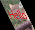
%IMG7%magick ^
toes.png ^
( -clone 0 ^
-alpha Transparent ^
-pointsize 100 -gravity Center ^
-fill Red ^
-annotate 0 Hello ^
) ^
( -clone 1 ^
-channel RGB -negate +channel ^
-blur 0x3 ^
) ^
+swap ^
-layers Merge ^
+write %SRC_LGE% ^
-resize 50%% ^
%SRC%
|


|
The mathematics, and processing of text files, is done in srt3d.h. This is a general-purpose module that does no image processing, so can be used in other programs. srt3d is a process module that uses srt3d.h, and can be run within an IM convert or magick command. For the source code, See
Process modules: scale, rotate and translate in 3d.
(However, I haven't yet tested this with v7.)
The options for the process module are:
| Option |
Description |
Short
form |
Long form |
| t string
|
transform string
|
Input transformation string.
Default: no string (so array is required). |
| a filename
|
array filename
|
Input transformation array: a text file with four lines, each with four numbers.
Can be "-" for stdin.
Default: no array (so string is required). |
| A filename
|
out-array filename
|
Output filename for transformation array.
Can be "-" for stdout.
Default: no output array. |
| c filename
|
coords filename
|
Input filename for coordinate list.
Note: the file is read multiple times, so "-" can't be used for stdin.
Default: no input coordinates, so the image corners will be used. |
| C filename
|
out-coords filename
|
Output filename for coordinate list.
Can be "-" for stdout.
Default: no output coordinates. |
| n integer
|
nOutCoords integer
|
Number of coordinates to output with C option.
Use 2 for just the x and y coordinates if you want to use the list in an IM "distort" command.
Default: 3 (x, y and z coordinates). |
| f number
|
focal-length number
|
Focal length for perspective.
Default: 0, no perspective. |
| r
|
hide-reverse
|
Hide reversed polygons. |
| h
|
help
|
Write some help to stdout. |
| v
|
verbose
|
Write some text output to stderr. |
|
|
version
|
Write version text to stdout. |
The most useful options are t transform, f focal-length and r hide-reverse. "A -" and "C -" are useful for debugging.
If input coordinates are not given with the coords option, image corners will be used for coordinates.
Required input: transformation string, or array. If both are supplied, the transformation string will be applied to the matrix.
If there is no image, the height and width (for purposes of percent etc) are taken as max input coordinate, plus one.
Rotating an image by exactly 90° (or 270°) in the x-axis or y-axis should result in a thin image, of zero thickness, which IM can't create. The process module catches this, and instead returns a 1x1 pixel transparent image. However, problems arise when the image is very nearly zero thickness, perhaps from arithmetical instability, when IM will take a long time creating a large image that is wrong. The process module can't readily detect this.
A workaround is to avoid rotations within 1° of 90° or 270°.
Some examples are shown, with output canvas settings. The canvas offsets give the shifts required to the image that would place the world origin (x=y=z=0) at the image top-left. This will be useful later on this page, when we build an image from multiple panels; we can simply "-layers merge" them to make their origins coincide.
|
Rotate around z-axis.
%IM7DEV%magick ^
  %SRC% ^
  -virtual-pixel Black ^
  -process 'srt3d transform rz10' ^
  +write s3d_t1.png ^
  -format "%%wx%%h %%g" info:
s3d.precision=8
154x140 154x140-21-1
|

|
|
Move centre to origin; rotate about x-axis.
%IM7DEV%magick ^
  %SRC% ^
  -virtual-pixel Black ^
  -process 'srt3d transform ty-50c,tx-50c,rx30' ^
  +write s3d_t2.png ^
  -format "%%wx%%h %%g" info:
s3d.precision=8
137x103 137x103-68-51
With no perspective, the only effect is vertical foreshortening.
|

|
|
As previous, but with perspective.
%IM7DEV%magick ^
  %SRC% ^
  -virtual-pixel Black ^
  -process 'srt3d transform ty-50c,tx-50c,rx30 f 400' ^
  +write s3d_t3.png ^
  -format "%%wx%%h %%g" info:
s3d.precision=8
147x104 147x104-73-48
|

|
|
Move centre to origin; rotate about x-axis and y-axis.
%IM7DEV%magick ^
  %SRC% ^
  -virtual-pixel Black ^
  -process 'srt3d transform ty-50c,tx-50c,rx30,ry60' ^
  +write s3d_t4.png ^
  -format "%%wx%%h %%g" info:
s3d.precision=8
119x103 119x103-59-51
With no perspective, the effect is foreshortening and shear.
|
|
|
As previous, but with perspective.
%IM7DEV%magick ^
  %SRC% ^
  -virtual-pixel Black ^
  -process 'srt3d transform ty-50c,tx-50c,rx30,ry60 f 400' ^
  +write s3d_t5.png ^
  -format "%%wx%%h %%g" info:
s3d.precision=8
120x120 120x120-66-57
|

|
|
Perspective can be negative.
%IM7DEV%magick ^
  %SRC% ^
  -virtual-pixel Black ^
  -process 'srt3d transform ty-50c,tx-50c,rx30,ry60 f -400' ^
  +write s3d_t6.png ^
  -format "%%wx%%h %%g" info:
s3d.precision=8
122x120 122x120-54-62
|

|
We animate ten frames, with rotation from zero to 90° in steps of 10°.
The command creates the ten frames, then one frame that is the "mosaic" of all ten frames, made transparent. Then all the frames are composited over that large transparent image, so now all the frames are the same size, with no offsets.
%IM7DEV%magick ^
  null: ^
  %SRC% ^
  -virtual-pixel None ^
  ( -clone 1 -process 'srt3d transform rz0' ) ^
  ( -clone 1 -process 'srt3d transform rz10' ) ^
  ( -clone 1 -process 'srt3d transform rz20' ) ^
  ( -clone 1 -process 'srt3d transform rz30' ) ^
  ( -clone 1 -process 'srt3d transform rz40' ) ^
  ( -clone 1 -process 'srt3d transform rz50' ) ^
  ( -clone 1 -process 'srt3d transform rz60' ) ^
  ( -clone 1 -process 'srt3d transform rz70' ) ^
  ( -clone 1 -process 'srt3d transform rz80' ) ^
  ( -clone 1 -process 'srt3d transform rz90' ) ^
  -delete 1 ^
  -layers trim-bounds ^
  ( -clone 1--1 ^
    -layers mosaic ^
    -alpha Transparent ^
  ) ^
  -insert 0 ^
  -layers Composite ^
  -set dispose Background ^
  s3d_a1.gif
|
|
GIF transparency is binary, so the edges are aliased.
The script
rot3dAnim.bat writes and calls a script for the multiple calls to the process module. By default, it flattens against white to avoid the binary transparency problem.
call %PICTBAT%rot3dAnim.bat ^
  s3d_src.png ^
  s3d_a2.gif
|

|
We can use the module in a fairly simple command to give a 3D view of a box, the panels of which are built from a source image.
We setup some parameters:
set DEPTH=60
set TRANS=ry20,rx-30
set PERSP=f 500
DEPTH is the number of pixels we will trim from the left and top, to make the left and top panels.
TRANS is a transformation we will apply to the entire box. Without any transformation, the left and top panels will be rotated away by 90°, so we see only the front panel. As we are building only the left and top, we should rotate around the y-axis in a positive direction up to 90°, and around the x-axis in a negative direction up to -90°. By doing it in this order, the y-axis remains vertical.
PERSP is the perspective distance, in pixels.
The command creates the left panel, then the top panel, then the front panel. The "+repage" to each panel zeros the offsets so the panel top-left coordinate is at the world origin (x=y=z=0), and the panel can then be transformed as required. A transformation "tx-1p" translates left by the ImageWidth-1, so the right side is at x=0. Finally, the panels are simply merged together.
%IM7DEV%magick ^
  %SRC_LGE% ^
  -virtual-pixel None -mattecolor None ^
  ( -clone 0 -crop %DEPTH%x+0+%DEPTH% +repage ^
    -process 'srt3d transform tx-1p,ry-90,%TRANS% %PERSP%' ^
  ) ^
  ( -clone 0 -crop x%DEPTH%+%DEPTH%+0 +repage ^
    -process 'srt3d transform ty-1p,rx90,%TRANS% %PERSP%' ^
  ) ^
  ( -clone 0 -crop x+%DEPTH%+%DEPTH% +repage ^
    -process 'srt3d transform %TRANS% %PERSP%' ^
  ) ^
  -delete 0 ^
  -background White ^
  -layers merge ^
  s3d_box.png
|

|
We can lighten the three visible edges by first lightening the pixels that will be at those edges. The intermediate result s3d_boxw.jpg is saved and shown for interest. We also simulate directional lighting by lightening the top panel and darkening the left panel.
%IM7DEV%magick ^
  %SRC_LGE% ^
  ( +clone ^
    -fill white -colorize 100 +write mpr:WHITE ^
    -virtual-pixel Black ^
    -blur 0x5 ^
    -roll +%DEPTH%+0 -roll +0+%DEPTH% ^
    -negate -auto-level ^
  ) ^
  mpr:WHITE +swap ^
  -compose Over -composite ^
+write s3d_boxw.jpg ^
  -virtual-pixel None -mattecolor None ^
  ( -clone 0 -crop %DEPTH%x+0+%DEPTH% +repage ^
    -channel RGB -evaluate Multiply 0.9 ^
    -process 'srt3d transform tx-1p,ry-90,%TRANS% %PERSP%' ^
  ) ^
  ( -clone 0 -crop x%DEPTH%+%DEPTH%+0 +repage ^
    -channel RGB -evaluate Multiply 1.1 ^
    -process 'srt3d transform ty-1p,rx90,%TRANS% %PERSP%' ^
  ) ^
  ( -clone 0 -crop x+%DEPTH%+%DEPTH% +repage ^
    -process 'srt3d transform %TRANS% %PERSP%' ^
  ) ^
  -delete 0 ^
  -background White ^
  -layers merge ^
  +repage ^
  s3d_box2.png
|


|
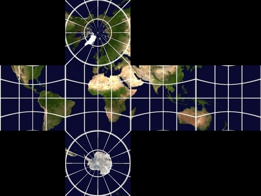
We can apply the same method to a cube, such as a cubic map of the earth.
set SRC_WLD=cubicWorld.jpg

for /F "usebackq" %%L in (`%IMG7%magick ^
  %SRC_WLD% ^
  -format "SQ_DIM=%%[fx:w/4]" ^
  info:`) do set %%L

echo SQ_DIM=%SQ_DIM%
SQ_DIM=128
|
|
This image is not my copyright. I borrowed it from
Creating Textures for Celestia.
We will create panels in this order: left, top, front, bottom, right, behind. To put that more graphically:
  2
1 3 5 6
  4
We have set SQ_DIM to the dimension of each square. We need multiples of this, and half of this, for offsets:
set /A SQ_DIM2=2*%SQ_DIM%
set /A SQ_DIM3=3*%SQ_DIM%
set /A SQ_DIM4=4*%SQ_DIM%
set /A SQ_DIM_2=%SQ_DIM%/2
We will apply a transformation and perspective to the assembled cube:
set TRANS=tx-%SQ_DIM_2%,ty-%SQ_DIM_2%,tz+%SQ_DIM_2%,ry20,rx-30
set PERSP=f 700
TRANS starts by transforming the centre of the sphere to the origin, then does the rotations.
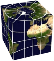
We can readily make an image with just three panels:
%IM7DEV%magick ^
  %SRC_WLD% ^
  -virtual-pixel None -mattecolor None ^
  ( -clone 0 -crop %SQ_DIM%x%SQ_DIM%+0+%SQ_DIM% +repage ^
    -process 'srt3d transform tx-1p,ry-90,%TRANS% %PERSP%' ^
  ) ^
  ( -clone 0 -crop %SQ_DIM%x%SQ_DIM%+%SQ_DIM%+0 +repage ^
    -process 'srt3d transform ty-1p,rx90,%TRANS% %PERSP%' ^
  ) ^
  ( -clone 0 -crop %SQ_DIM%x%SQ_DIM%+%SQ_DIM%+%SQ_DIM% +repage ^
    -process 'srt3d transform %TRANS% %PERSP%' ^
  ) ^
  -delete 0 ^
  -background White -layers merge ^
  s3d_wld3.png
|

|
Then we add the other panels:
%IM7DEV%magick ^
  %SRC_WLD% ^
  -virtual-pixel None -mattecolor None ^
  ( -clone 0 -crop %SQ_DIM%x%SQ_DIM%+0+%SQ_DIM% +repage ^
    -process 'srt3d transform tx-1p,ry-90,%TRANS% %PERSP% r' ^
  ) ^
  ( -clone 0 -crop %SQ_DIM%x%SQ_DIM%+%SQ_DIM%+0 +repage ^
    -process 'srt3d transform ty-1p,rx90,%TRANS% %PERSP% r' ^
  ) ^
  ( -clone 0 -crop %SQ_DIM%x%SQ_DIM%+%SQ_DIM%+%SQ_DIM% +repage ^
    -process 'srt3d transform %TRANS% %PERSP% r' ^
  ) ^
  ( -clone 0 -crop %SQ_DIM%x%SQ_DIM%+%SQ_DIM%+%SQ_DIM2% +repage ^
    -process 'srt3d transform rx-90,ty%SQ_DIM%,%TRANS% %PERSP% r' ^
  ) ^
  ( -clone 0 -crop %SQ_DIM%x%SQ_DIM%+%SQ_DIM2%+%SQ_DIM% +repage ^
    -process 'srt3d transform ry90,tx%SQ_DIM%,%TRANS% %PERSP% r' ^
  ) ^
  ( -clone 0 -crop %SQ_DIM%x%SQ_DIM%+%SQ_DIM3%+%SQ_DIM% +repage ^
    -process 'srt3d transform ry180,tx%SQ_DIM%,tz-%SQ_DIM%,%TRANS% %PERSP% r' ^
  ) ^
  -delete 0 ^
  -background White -layers merge ^
  s3d_wld4.png
|
|
While developing the above command, I included a "+write Xn.png" for each panel to check for the correct crops, and I had "+delete" operations for some panels so I could see other panels. Then I removed each "+write" and "+delete", and added "r" to each srt3d process, which hides the panels that are reversed.
The srt3d option "r" or "hide-reversed" calculates the array and coordinates as usual. It then calculates the two areas made by the input and output coordinates projected on the xy-plane (ie by ignoring the z-coordinate). The area is positive if the coordinates are listed in clockwise order, or negative if in anti-clockwise order. If the output area is very close to zero, or the signs of the areas are different, the image is hidden. This means the process module creates a 1x1 image that is transparent.
An alternative mechanism would be to sort the images in z-order, also known as the painter's algorithm.
We put the above command into a script,
rotCubeAnim.bat, inside a loop that varies the rotation around the y-axis.
call %PICTBAT%rotCubeAnim ^
  cubicWorld.jpg s3d_a3.gif
|
|
The process module can read and write transformation arrays. If the module reads a transformation array, the transformation string is applied to that array, instead of to the identity array.
The file format for arrays is four lines, each of four comma-separated numbers.
A null transformation, written to stdout:
%IM7DEV%magick xc: -process 'srt3d A -' NULL:
s3d.precision=8
precision=8
1, 0, 0, 0
0, 1, 0, 0
0, 0, 1, 0
0, 0, 0, 1
Rotate around x by 30°, and save array to a file:
%IM7DEV%magick xc: -process 'srt3d t rx30 A s3d_ct2.lis' NULL:
1, 0, 0, 0
0, 0.8660254, -0.5, 0
0, 0.5, 0.8660254, 0
0, 0, 0, 1
Read the previous array, and rotate around y by 10°:
%IM7DEV%magick xc: -process 'srt3d a s3d_ct2.lis t ry10 A -' NULL:
s3d.precision=8
precision=8
0.98480775, 0.086824089, 0.15038373, 0
0, 0.8660254, -0.5, 0
-0.17364818, 0.49240388, 0.85286853, 0
0, 0, 0, 1
For comparison: rotate around x by 30° and around y by 10°:
%IM7DEV%magick xc: -process 'srt3d t rx30,ry10 A -' NULL:
s3d.precision=8
precision=8
0.98480775, 0.086824089, 0.15038373, 0
0, 0.8660254, -0.5, 0
-0.17364818, 0.49240388, 0.85286853, 0
0, 0, 0, 1
This gives the same result, as expected.
For convenience, .bat scripts are also available in a single zip file. See
Zipped BAT files.
@rem
@rem Updated:
@rem   29-August-2022 for IM v7.
@rem

set INFILE=%1
set OUTFILE=%2

set A_START=1
set A_END=351
set A_STEP=10

if "%r3dBACK_COL%"=="" set r3dBACK_COL=white

set T_STR=srt3d t tx-50c,ty-50c,rx30,ry_XX_ f 500 v


set TMP_SCR=\temp\s3dtmp.scr

(
echo null:
echo %INFILE%
echo -virtual-pixel None -mattecolor None

for /L %%A in (%A_START%,%A_STEP%,%A_END%) do @(
  set V_STR=!T_STR:_XX_=%%A!
  @echo ^( -clone 1 -process '!V_STR!' ^)
)

echo -delete 1
echo -layers trim-bounds
echo ^( -clone 1--1
echo   -layers mosaic
if /I "%r3dBACK_COL%"=="none" (
  echo   -alpha Transparent
) else (
  echo   -fill %r3dBACK_COL% -colorize 100
)
echo ^)
echo -insert 0
echo -compose Over -layers Composite
echo -alpha off
echo -background White -set dispose Background
echo +write %OUTFILE%
echo -exit
) >%TMP_SCR%

type %TMP_SCR%

%IM7DEV%magick -script %TMP_SCR%
@rem
@rem Updated:
@rem   29-August-2022 for IM v7.
@rem

set INFILE=%1
set OUTFILE=%2

set A_START=5
set A_END=355
set A_STEP=10


set SQ_DIM=
for /F "usebackq" %%L in (`%IMG7%magick ^
  %INFILE% ^
  -format "SQ_DIM=%%[fx:w/4]" ^
  info:`) do set %%L
if "%SQ_DIM%"=="" exit /B 1

echo SQ_DIM=%SQ_DIM%


set /A SQ_DIM2=2*%SQ_DIM%
set /A SQ_DIM3=3*%SQ_DIM%
set /A SQ_DIM4=4*%SQ_DIM%
set /A SQ_DIM_2=%SQ_DIM%/2

set DEPTH=60
set TRANS=tx-%SQ_DIM_2%,ty-%SQ_DIM_2%,tz+%SQ_DIM_2%,ry_XX_,rx-30
set PERSP=f 700

del rca_tmp_*.miff 2>nul

for /L %%A in (%A_START%,%A_STEP%,%A_END%) do @(
  set LZ=00%%A
  set LZ=!LZ:~-3!
  echo !LZ!

  set TMP_OUT=rca_tmp_!LZ!.miff

  set TRANS_STR=%TRANS:_XX_=!LZ!%
  echo TMP_OUT=!TMP_OUT!  TRANS_STR=!TRANS_STR!

  %IM7DEV%magick ^
    %INFILE% ^
    -virtual-pixel None -mattecolor None ^
    ^( -clone 0 -crop %SQ_DIM%x%SQ_DIM%+0+%SQ_DIM% +repage ^
       -process 'srt3d transform tx-1p,ry-90,!TRANS_STR! %PERSP% r' ^
    ^) ^
    ^( -clone 0 -crop %SQ_DIM%x%SQ_DIM%+%SQ_DIM%+0 +repage ^
       -process 'srt3d transform ty-1p,rx90,!TRANS_STR! %PERSP% r' ^
    ^) ^
    ^( -clone 0 -crop %SQ_DIM%x%SQ_DIM%+%SQ_DIM%+%SQ_DIM% +repage ^
       -process 'srt3d transform !TRANS_STR! %PERSP% r' ^
    ^) ^
    ^( -clone 0 -crop %SQ_DIM%x%SQ_DIM%+%SQ_DIM%+%SQ_DIM2% +repage ^
       -process 'srt3d transform rx-90,ty%SQ_DIM%,!TRANS_STR! %PERSP% r' ^
    ^) ^
    ^( -clone 0 -crop %SQ_DIM%x%SQ_DIM%+%SQ_DIM2%+%SQ_DIM% +repage ^
       -process 'srt3d transform ry90,tx%SQ_DIM%,!TRANS_STR! %PERSP% r' ^
    ^) ^
    ^( -clone 0 -crop %SQ_DIM%x%SQ_DIM%+%SQ_DIM3%+%SQ_DIM% +repage ^
       -process 'srt3d transform ry180,tx%SQ_DIM%,tz-%SQ_DIM%,!TRANS_STR! %PERSP% r' ^
    ^) ^
    -delete 0 ^
    -background White -layers merge ^
    !TMP_OUT!
)

%IMG7%magick ^
  null: ^
  -virtual-pixel None -mattecolor None ^
  rca_tmp_*.miff ^
  -layers trim-bounds ^
  ^( -clone 1--1 ^
     -layers mosaic ^
     -alpha Transparent ^
  ^) ^
  -insert 0 ^
  -layers Composite ^
  -set dispose Background ^
  %OUTFILE%

del rca_tmp_*.miff 2>nul
All images on this page were created by the commands shown, using:
%IMG7%magick -version
Version: ImageMagick 7.1.0-47 Q16-HDRI x64 15861e0:20220827 https://imagemagick.org
Copyright: (C) 1999 ImageMagick Studio LLC
License: https://imagemagick.org/script/license.php
Features: Cipher DPC HDRI OpenCL
Delegates (built-in): bzlib cairo freetype gslib heic jng jp2 jpeg jxl lcms lqr lzma openexr pangocairo png ps raqm raw rsvg tiff webp xml zip zlib
Compiler: Visual Studio 2022 (193331629)
To improve internet download speeds, some images may have been automatically converted (by ImageMagick, of course) from PNG or TIFF or MIFF to JPG.
Source file for this web page is srt3d.h1. To re-create this web page, execute "procH1 srt3d".
This page, including the images except where shown otherwise, is my copyright. Anyone is permitted to use or adapt any of the code, scripts or images for any purpose, including commercial use.
Anyone is permitted to re-publish this page, but only for non-commercial use.
Anyone is permitted to link to this page, including for commercial use.
Page version v1.0 31-May-2017.
Page created 18-Sep-2022 21:02:50.
Copyright © 2022 Alan Gibson.