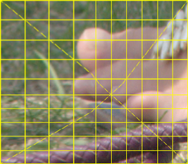
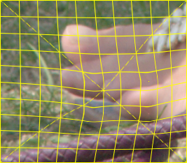
call %PICTBAT%gridOver ^
  toes.png pop_src.png 10 10

set SRC=pop_src.png

We can push pixels to new locations while pinning others in place.
This page does not consider how the user might specify the displacement. A trimap can specify which pixels are pinned, or pushed to new locations, or are free to move or not. I can't see an elegant graphical method for specifying new locations for pushed pixels. This could be simple text coordinates, of course.
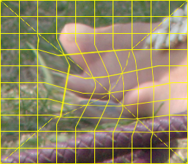
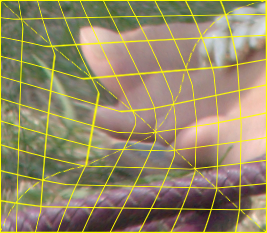
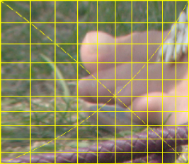
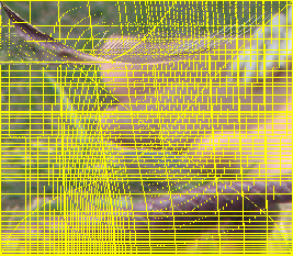
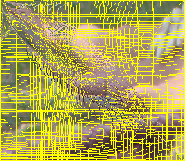
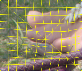
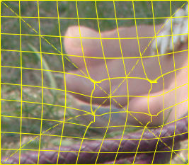
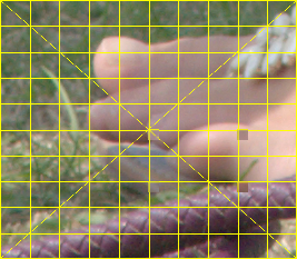
We demonstrate with a photograph that has an overlaid grid.
call %PICTBAT%gridOver ^ toes.png pop_src.png 10 10 set SRC=pop_src.png |
|
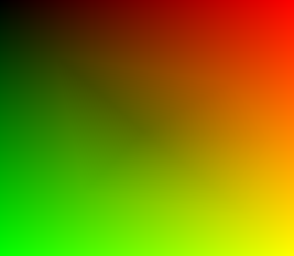
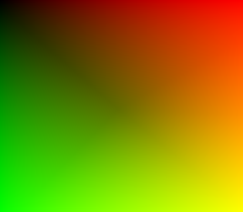
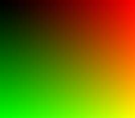
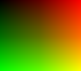
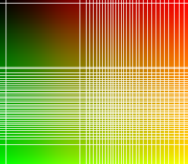
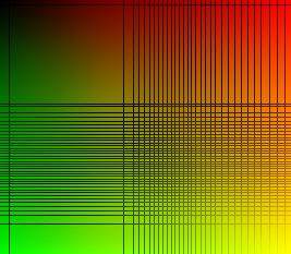
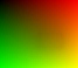
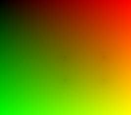
We also make an identity absolute displacement map.
set IDENT=^ 0,0,#000,^ %%[fx:w-1],0,#f00,^ 0,%%[fx:h-1],#0f0,^ %%[fx:w-1],%%[fx:h-1],#ff0 %IMG7%magick ^ %SRC% ^ -strip ^ -sparse-color bilinear "%IDENT%" ^ pop_id_abs_map.png |

|
On this page, ordinary absolute displacement maps are called "pull" maps, because the value at a pixel in the map determines where the corresponding pixel in the final image comes from. We use the process module invdispmap to invert the map, making a "push" map, which determines where the corresponding pixel in the final image will be pushed to. The process invdispmap also does the opposite, converting a push map into a pull map. The inversion process leaves holes that we fill by relaxation.
The identity absolute displacement map creates no displacement, so can be regarded as either a pull map or a push map.
Suppose we have a shape, defined by a mask that is white on a black background. In an image of the same size, we want to move a point at (x1,y1) to another location (x2,y2), where both locations are within the white area defined by the mask. However, we want to pin all the pixels that are outside the shape, so they don't move. Intermediate pixels should move in proportion.
This is the more general case of pinning the four edges of the image.
We can create a gradient that is white at (x2,y2) and black at outside the white area defined by the mask. This can be used as a blend for two displacement maps. One displacement map is the required translation from (x1,y1) to (x2,y2), and the other is the identity displacement map.
For example, the locations are:
set X1=100
set Y1=100
set X2=130
set Y2=120
We show each step of the process:
|
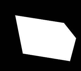
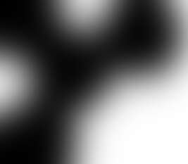
Make a mask with white shape on black background %IMG7%magick ^ -size 267x233 xc:Black ^ -fill White -stroke None ^ -draw "polygon 50,50 210,75 250,125 230,200 75,175" ^ pop_poly.png |
|
|
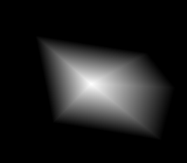
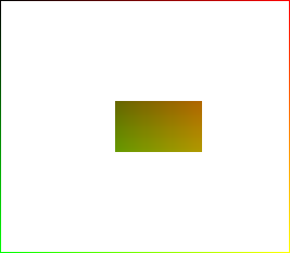
Make the gradient call %PICTBAT%shp2grad ^ pop_poly.png ^ pop_poly_grad.miff ^ %X2%x%Y2% -negate %IMG7%magick ^ pop_poly_grad.miff pop_poly_grad.png The MIFF version has negative values outside the shape. We also save, and show, a (clamped) PNG version. |
|
|
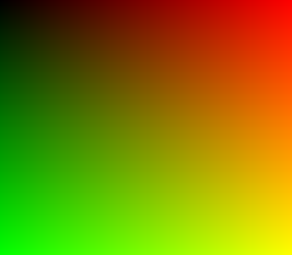
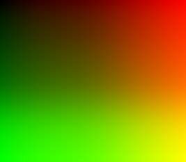
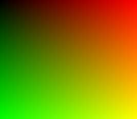
Make the identity displacement map %IMG7%magick -size 267x233 xc: ^ -sparse-color Bilinear ^ 0,0,#000,^ %%[fx:w-1],0,#f00,^ 0,%%[fx:h-1],#0f0,^ %%[fx:w-1],%%[fx:h-1],#ff0 ^ pop_poly_ident.png |
|
|
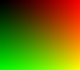
Modify the map for movement.
%IMG7%magick ^
  pop_poly_ident.png ^
  -channel R ^
  -evaluate pow ^
    %%[fx:log(%X1%/(w-1))/log(%X2%/(w-1))] ^
  -channel G ^
  -evaluate pow ^
    %%[fx:log(%Y1%/(h-1))/log(%Y2%/(h-1))] ^
  +channel ^
  pop_poly_move.png
|
|
|
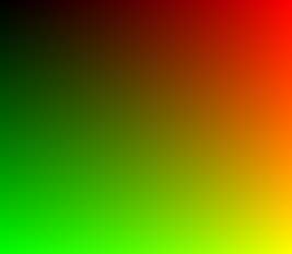
Blend the maps %IMG7%magick ^ pop_poly_ident.png ^ pop_poly_move.png ^ pop_poly_grad.png ^ -alpha off ^ -compose Over -composite ^ pop_poly_blnd.png |
|
|
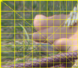
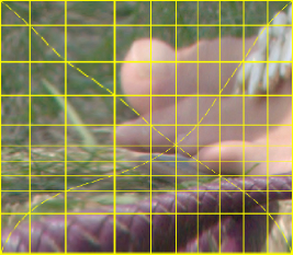
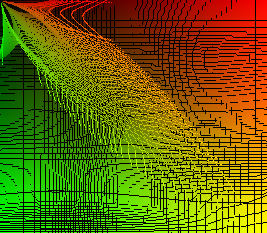
Apply the blended map %IMG7%magick ^ %SRC% ^ pop_poly_blnd.png ^ -compose Distort -composite ^ pop_poly_out.png |
|
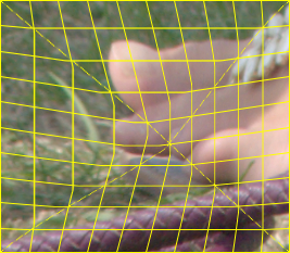
The broken grid lines (second order discontinuity) can be fixed by modifying the blending function. "-sigmoidal-contrast" smooths the start and end of the transition, so the grid lines mostly have curves instead of breaks, and "-blur" smooths minor problems.
|
Blend the maps, with modified blend %IMG7%magick ^
pop_poly_ident.png ^
pop_poly_move.png ^
( pop_poly_grad.png ^
-sigmoidal-contrast 5,50%% ^
-blur 0x5 ^
) ^
-alpha off ^
-compose Over -composite ^
pop_poly_blnd2.png
|
|
|
Apply the modified blended map %IMG7%magick ^ %SRC% ^ pop_poly_blnd2.png ^ -compose Distort -composite ^ pop_poly_out2.png |
|
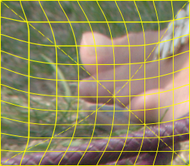
If we want the distortion to continue outside the shape (but in the opposite direction) we need to use the floating-point version of the gradient pop_poly_grad.miff, and we can't -blur it as that clamps:
|
Blend the maps, with modified blend %IMG7%magick ^ pop_poly_ident.png ^ pop_poly_move.png ^ -define compose:clamp=off ^ pop_poly_grad.miff ^ -alpha off ^ -compose Over -composite ^ -depth 32 -define quantum:format=floating-point ^ -write pop_poly_blnd3.miff ^ pop_poly_blnd3.png |
|
|
Apply the modified blended map %IMG7%magick ^ %SRC% ^ pop_poly_blnd3.miff ^ -compose Distort -composite ^ pop_poly_out3.png The boundary of the shape is not obvious. |
|
This is a specialisation of the above. Instead of finding the gradient within a shape, we find it within the image as a whole. We do the work in a script move1PinEdge.bat.
call %PICTBAT%move1PinEdge ^ %SRC% pop_move1.png ^ %X1%x%Y1% %X2%x%Y2% |
|
call %PICTBAT%move1PinEdge ^ %SRC% pop_move1b.png ^ %X1%x%Y1% %X2%x%Y2% ^ "-sigmoidal-contrast 5,50%%% -blur 0x5" |
|
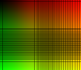
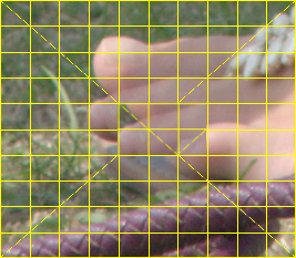
We first consider a special case: we move coordinate (x1,y1) to (x2,y2), by moving an entire column from x1 to x2, and an entire row from y1 to y2. All other pixels should move in a "reasonable" way. Pixels at the top and bottom edge will move left or right. Pixels at the left or right edge will move up or down. Corner pixels won't move at all.
set X1=100
set Y1=100
set X2=130
set Y2=120
We can crop into two pieces horizontally at X1, then resize each, and append them together. Then we do the same vertically.
set sFMT=^
WW=%%w\n^
HH=%%h\n^
WR1=%%[fx:w-%X1%]\n^
WR2=%%[fx:w-%X2%]\n^
HB1=%%[fx:h-%Y1%]\n^
HB2=%%[fx:h-%Y2%]

for /F "usebackq" %%L in (`%IMG7%magick ^
  identify ^
  -format "%sFMT%"
  %SRC%`) do set %%L

%IMG7%magick ^
  %SRC% ^
  ( -clone 0 ^
    -crop %X1%x+0+0 +repage ^
    -resize "%X2%x^!" ^
  ) ^
  ( -clone 0 ^
    -crop %WR1%x+%X1%+0 +repage ^
    -resize "%WR2%x^!" ^
  ) ^
  -delete 0 ^
  +append +repage ^
  ( -clone 0 ^
    -crop x%Y1%+0+0 +repage ^
    -resize "x%Y2%^!" ^
  ) ^
  ( -clone 0 ^
    -crop x%HB1%+0+%Y1% +repage ^
    -resize "x%HB2%^!" ^
  ) ^
  -delete 0 ^
  -append +repage ^
  pop_li1.png
|
|
The abrupt change of scale is obvious in the "broken" diagonal lines.
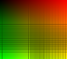
A single point can be moved by applying a power (gamma) function to the gradients of the identity map. This is a pull map, so the value at coordinate (x2,y2) should be x1 in the red channel and y1 in the green channel.
We raise to the power k such that:
v' = v^k

log(v') = log(v^k)  (where log is to any base)
        = k * log(v)

k = log(v') / log(v)
We use v7, so the calculation can be done within the "-evaluate pow".
|
Make a displacement map. %IMG7%magick ^
pop_id_abs_map.png ^
-channel R ^
-evaluate pow ^
%%[fx:log(%X1%/(w-1))/log(%X2%/(w-1))] ^
-channel G ^
-evaluate pow ^
%%[fx:log(%Y1%/(h-1))/log(%Y2%/(h-1))] ^
+channel ^
pop_pc_map.png
|
|
|
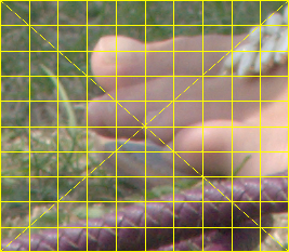
Apply the map. %IMG7%magick ^ %SRC% ^ pop_pc_map.png ^ -compose Distort -composite ^ pop_pc1.png |
|
There is no abrupt change of scale, but stretching at the left and top edges is severe.
Iterating the above won't move multiple points, because moving any one point uniquely determines the movement of all the others. A power (gamma) curve is determined by a single point.
The obvious solution is a Bézier curve, which is determined by however many points we want. An external program, cBezCurve.exe, calculates values along a Bézier curve, creating an Nx1 clut image. We use this twice, for the two dimensions.
(I don't publish the source or binary of cBezCurve.exe. The program calculates "reasonable" coordinates for the required extra control points.)
Get the dimensions.
for /F "usebackq" %%L in (`%IMG7%magick identify ^
  -format "WW=%%w\nHH=%%h\nWm1=%%[fx:w-1]\nHm1=%%[fx:h-1]" ^
  %SRC%`) do set %%L

echo WW=%WW% HH=%HH%
WW=267 HH=233
Make a WWx1 clut for the horizontal displacement. This is really a slightly distorted gradient. At ordinate X2, we want value X1. We also pin the first and last ordinates, 0 and %Wm1%.
cBezCurve /p0 /C /a1 /m%Wm1% /I"0,0; %X2%,%X1%; %Wm1%,%Wm1%" /n%WW% /T1 /F0 /Lpop_dx.ppm
Similarly, a HHx1 clut for the vertical displacement.
cBezCurve /p0 /C /a1 /m%Hm1% /I"0,0; %Y2%,%Y1%; %Hm1%,%Hm1%" /n%HH% /T1 /F0 /Lpop_dy.ppm
Use these two cluts to make a displacement map. We have told cBezCurve.exe to create just the red channel, so combining them is slightly complex. We need the red channel of the first PPM to go into the red channel of the map, and red channel of the second PPM to go into the green channel of the map.
|
Make a displacement map. %IMG7%magick ^ pop_dx.ppm ^ ( pop_dy.ppm -rotate 90 ) ^ xc:Black ^ -channel R ^ -scale "%WW%x%HH%^!" ^ -separate ^ +channel ^ -combine ^ pop_pmp_map.png |
|
|
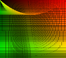
Apply the map. %IMG7%magick ^ %SRC% ^ pop_pmp_map.png ^ -compose Distort -composite ^ pop_pmp1.png |
|
The result is similar to the one from the power (gamma) curve, but with less severe stretching at the left and top edges.
cBezCurve.exe has other interpolation methods, such as linear:
cBezCurve /p0 /C /a1 /m%Wm1% /I"0,0; %X2%,%X1%; %Wm1%,%Wm1%" /n%WW% /T0 /F0 /Lpop_dx1a.ppm

cBezCurve /p0 /C /a1 /m%Hm1% /I"0,0; %Y2%,%Y1%; %Hm1%,%Hm1%" /n%HH% /T0 /F0 /Lpop_dy1a.ppm
|
Make a displacement map. %IMG7%magick ^ pop_dx1a.ppm ^ ( pop_dy1a.ppm -rotate 90 ) ^ xc:Black ^ -channel R ^ -scale "%WW%x%HH%^!" ^ -separate ^ +channel ^ -combine ^ pop_pmp_map1a.png |
|
|
Apply the map. %IMG7%magick ^ %SRC% ^ pop_pmp_map1a.png ^ -compose Distort -composite ^ pop_pmp1a.png The result is essentially the same as the crop-resize method above. |

|
With Bézier curves, we can push as many pixels as we like. Morever, the same mechanism can pin pixels; we simply give the same coordinates for input and output.
set pinX=30
set pinY=25

set X3=50
set Y3=200
set X4=55
set Y4=185

set X5=200
set Y5=50
set X6=210
set Y6=60

set NewX=%pinX%,%pinX%; %X4%,%X3%; %X6%,%X5%

set NewY=%pinY%,%pinY%; %Y4%,%Y3%; %Y6%,%Y5%
Make the cluts:
cBezCurve /p0 /C /a1 /m%Wm1% /I"0,0; %X2%,%X1%; %NewX%; %Wm1%,%Wm1%" /n%WW% /T1 /F0 /Lpop_dx2.ppm

cBezCurve /p0 /C /a1 /m%Hm1% /I"0,0; %Y2%,%Y1%; %NewY%; %Hm1%,%Hm1%" /n%HH% /T1 /F0 /Lpop_dy2.ppm
|
Make a displacement map. %IMG7%magick ^ pop_dx2.ppm ^ ( pop_dy2.ppm -rotate 90 ) ^ xc:Black ^ -channel R ^ -scale "%WW%x%HH%^!" ^ -separate ^ +channel ^ -combine ^ pop_pmp_map2.png |
|
|
Apply the map. %IMG7%magick ^ %SRC% ^ pop_pmp_map2.png ^ -compose Distort -composite ^ pop_pmp2.png |
|
When we move X1,Y1 to X2,Y2, all pixels on row Y1 will move to row Y2, and all pixels on column X1 will move to column X2. Hence, input lines that were vertical or horizontal will be vertical or horizontal in the output.
We could invert the map, getting a push (instead of pull) map. This could be modulated, eg reduced except in the vicinity of points, and converted back to a pull map. For example, we modulate with a gradient so we have no displacement at the top:
|
Invert, to get a push map. %IM7DEV%magick ^ pop_pmp_map2.png ^ -process invdispmap ^ pop_pmp_map2i.png |
|
|
Fill by relaxation. set rfCOMP_METRIC=PAE set THRESH=1e-4 set NUM_ITER=1000 call %PICTBAT%relaxFillMS ^ pop_pmp_map2i.png . pop_pmp_maprf.png ^ %THRESH% %NUM_ITER% We will use this push map a few times. |
|
|
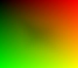
Blend with identity map, to get zero displacement at the top and full displacement at the bottom. %IMG7%magick ^ pop_pmp_maprf.png ^ pop_id_abs_map.png ^ -size %WW%x%HH% gradient: ^ -compose Over -composite ^ pop_pmp_mapbld.png |
|
|
Invert, to get a pull map. %IM7DEV%magick ^ pop_pmp_mapbld.png ^ -process invdispmap ^ pop_pmp_mapbldi.png |

|
|
Fill by relaxation. call %PICTBAT%relaxFillMS ^ pop_pmp_mapbldi.png . pop_pmp_mapbirf.png ^ %THRESH% %NUM_ITER% |
|
|
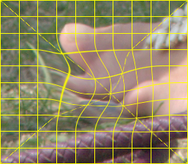
Apply the map. %IMG7%magick ^ %SRC% ^ pop_pmp_mapbirf.png ^ -compose Distort -composite ^ pop_pmp_bld.png |
|
In the next example, we get the full displacement at the required points, and decreasing displacement further from any points. We are modifying the push map, so we want a mask that is black at the original locations of pinned or pushed pixels.
|
Black where we have a point; otherwise white. %IMG7%magick ^
-size %WW%x%HH% ^
xc:White ^
-fill Black ^
-draw ^
"point %pinX%,%pinY% point %X1%,%Y1% point %X3%,%Y3% point %X5%,%Y5% " ^
pop_pnt_mask.png
|

|
%IMG7%magick ^ pop_pnt_mask.png ^ -morphology Distance Euclidean:7,100 ^ -auto-level ^ pop_pnt_mask2.png |
|
|
Blend with identity map. %IMG7%magick ^ pop_pmp_maprf.png ^ pop_id_abs_map.png ^ pop_pnt_mask2.png ^ -compose Over -composite ^ pop_pmp_mapbld2.png |
|
|
Invert, to get a pull map. %IM7DEV%magick ^ pop_pmp_mapbld2.png ^ -process invdispmap ^ pop_pmp_mapbld2i.png |
|
|
Fill by relaxation. call %PICTBAT%relaxFillMS ^ pop_pmp_mapbld2i.png . pop_pmp_maprf2.png ^ %THRESH% %NUM_ITER% |

|
|
Apply the map. %IMG7%magick ^ %SRC% ^ pop_pmp_maprf2.png ^ -compose Distort -composite ^ pop_pmp_bld2.png |
|
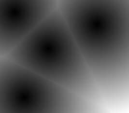
Another possibility: apply the full effect only in a circle around each point. The radius at each point probably needs to be sufficient to cover the displacement. For simplicity, we use the same radius and blur for all the circles.
|
Draw circles, and blur them. set sCIRC=circle 0,0 0,60 %IMG7%magick ^ -size %WW%x%HH% ^ xc:White ^ -fill Black ^ -draw "translate %pinX%,%pinY% %sCIRC%" ^ -draw "translate %X1%,%Y1% %sCIRC%" ^ -draw "translate %X3%,%Y3% %sCIRC%" ^ -draw "translate %X5%,%Y5% %sCIRC%" ^ -blur 0x25 ^ pop_pnt_mask3.png |
|
|
Blend with identity map. %IMG7%magick ^ pop_pmp_maprf.png ^ pop_id_abs_map.png ^ pop_pnt_mask3.png ^ -compose Over -composite ^ pop_pmp_mapbld3.png |

|
|
Invert, to get a pull map. %IM7DEV%magick ^ pop_pmp_mapbld3.png ^ -process invdispmap ^ pop_pmp_mapbld3i.png |

|
|
Fill by relaxation. call %PICTBAT%relaxFillMS ^ pop_pmp_mapbld3i.png . pop_pmp_maprf3.png ^ %THRESH% %NUM_ITER% |

|
|
Apply the map. %IMG7%magick ^ %SRC% ^ pop_pmp_maprf3.png ^ -compose Distort -composite ^ pop_pmp_bld3.png |

|
Above, we have pinned or pushed individual pixels. (Strictly speaking, individual coordinates.) Instead, we can pin or push groups of pixels. All the pixels in each group will be displaced by the same amount. The method shown here is in general quite complex, but simple enough when each area is a rectangle (so this also includes horizontal and vertical lines).
The method is to either construct an identity absolute displacement map and move the areas, making the other pixels transparent, or to make a relative displacement map with areas of the appropriate shade of gray.
Each pixel in the displacement map is one of:
Transparent pixels in the displacement map are then filled by the relaxation method, and the map is used to displace the input image.
IM v6 can't have %[fx:] in -crop, so we use v7. For the edges of the map, early versions of v7 don't have "-region" so we do the job with four crops.
set sEDGES=^
  ( -clone 0 -crop %%[fx:w]x1+0+0 ) ^
  ( -clone 0 -crop %%[fx:w]x1+0+%%[fx:h-1] ) ^
  ( -clone 0 -crop 1x%%[fx:h]+0+0 ) ^
  ( -clone 0 -crop 1x%%[fx:h]+%%[fx:w-1]+0 )
%IMG7%magick ^
  pop_id_abs_map.png ^
  ( -clone 0 -alpha transparent ) ^
  %sEDGES% ^
  ( -clone 0 ^
    -crop %%[fx:w*0.3]x%%[fx:h*0.2]+%%[fx:w*0.4]+%%[fx:h*0.4] ^
  ) ^
  -delete 0 ^
  -background None ^
  -layers flatten ^
  pop_map1.png
|
|
set rfCOMP_METRIC=PAE set THRESH=1e-4 set NUM_ITER=1000 rem set rfCOMP_METRIC=RMSE rem set THRESH=1e-6 call %PICTBAT%relaxFillMS ^ pop_map1.png . . %THRESH% %NUM_ITER% |
|
|
We should have no displacement: %IMG7%magick ^ %SRC% ^ pop_map1_rfms.png ^ -compose Distort -composite ^ pop_m1.png |

|
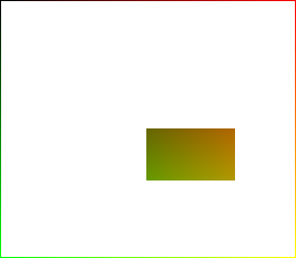
Displace a central block:
%IMG7%magick ^
  pop_id_abs_map.png ^
  ( -clone 0 -alpha transparent ) ^
  %sEDGES% ^
  ( -clone 0 ^
    -set DW %%[fx:w*0.1] ^
    -set DH %%[fx:h*0.1] ^
    -crop %%[fx:w*0.3]x%%[fx:h*0.2]+%%[fx:w*0.4]+%%[fx:h*0.4] ^
    -repage "+%%[DW]+%%[DH]^!" ^
  ) ^
  -delete 0 ^
  -background None ^
  -layers flatten ^
  pop_map2.png
|
|
call %PICTBAT%relaxFillMS ^ pop_map2.png . . %THRESH% %NUM_ITER% |
|
%IMG7%magick ^ %SRC% ^ pop_map2_rfms.png ^ -compose Distort -composite ^ pop_m2.png |

|
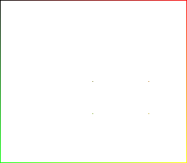
Displace the four corners of a central block:
set sREPAGE=-repage "+%%[DW]+%%[DH]^^^!"

%IMG7%magick ^
  pop_id_abs_map.png ^
  -set DW %%[fx:w*0.1] ^
  -set DH %%[fx:h*0.1] ^
  ( -clone 0 -alpha transparent ) ^
  %sEDGES% ^
  ( -clone 0 ^
    -crop 1x1+%%[fx:w*0.4]+%%[fx:h*0.4] ^
    %sREPAGE% ^
  ) ^
  ( -clone 0 ^
  -set DW %%[fx:w*0.1] ^
  -set DH %%[fx:h*0.1] ^
    -crop 1x1+%%[fx:w*0.7]+%%[fx:h*0.4] ^
    %sREPAGE% ^
  ) ^
  ( -clone 0 ^
    -crop 1x1+%%[fx:w*0.4]+%%[fx:h*0.6] ^
    %sREPAGE% ^
  ) ^
  ( -clone 0 ^
    -crop 1x1+%%[fx:w*0.7]+%%[fx:h*0.6] ^
    %sREPAGE% ^
  ) ^
  -delete 0 ^
  -background None ^
  -layers flatten ^
  pop_map3.png
|
|
call %PICTBAT%relaxFillMS ^ pop_map3.png . . %THRESH% %NUM_ITER% |
|
%IMG7%magick ^ %SRC% ^ pop_map3_rfms.png ^ -compose Distort -composite ^ pop_m3.png |
|
The displacement is not as far as we wanted. Repeat the previous, but without multi-scale:
call %PICTBAT%relaxFill ^ pop_map3.png . pop_map3a_rfms.png ^ %THRESH% %NUM_ITER% |
|
%IMG7%magick ^ %SRC% ^ pop_map3a_rfms.png ^ -compose Distort -composite ^ pop_m3a.png |
|
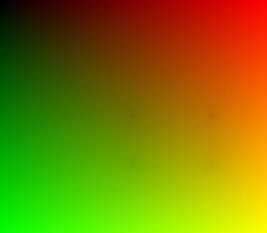
This hasn't cured the problem.
Sadly, the process doesn't work well when we have isolated pixels in the holed image. The pixel at (50%,50%) has the correct value of RG=(40%,40%), but moving away from this pixel, the values swiftly rise.
Try moving small squares, one at each location:
set rfCOMP_METRIC=PAE
set THRESH=1e-4
set NUM_ITER=1000

set sREPAGE=-repage "+%%[DW]+%%[DH]^^^!"

set SW=10
set SH=10

%IMG7%magick ^
  pop_id_abs_map.png ^
  -set DW %%[fx:w*0.1] ^
  -set DH %%[fx:h*0.1] ^
  ( -clone 0 -alpha transparent ) ^
  %sEDGES% ^
  ( -clone 0 ^
    -crop %SW%x%SH%+%%[fx:w*0.4]+%%[fx:h*0.4] ^
    %sREPAGE% ^
  ) ^
  ( -clone 0 ^
  -set DW %%[fx:w*0.1] ^
  -set DH %%[fx:h*0.1] ^
    -crop %SW%x%SH%+%%[fx:w*0.7]+%%[fx:h*0.4] ^
    %sREPAGE% ^
  ) ^
  ( -clone 0 ^
    -crop %SW%x%SH%+%%[fx:w*0.4]+%%[fx:h*0.6] ^
    %sREPAGE% ^
  ) ^
  ( -clone 0 ^
    -crop %SW%x%SH%+%%[fx:w*0.7]+%%[fx:h*0.6] ^
    %sREPAGE% ^
  ) ^
  -delete 0 ^
  -background None ^
  -layers flatten ^
  pop_map4.png
|
|
call %PICTBAT%relaxFillMS ^ pop_map4.png . . %THRESH% %NUM_ITER% |
|
%IMG7%magick ^ %SRC% ^ pop_map4_rfms.png ^ -compose Distort -composite ^ pop_m4.png |
|
Relative displacement maps are simpler, as each rectangle is a constant shade of gray.
%IMG7%magick ^
  %SRC% ^
  -shave 1x1 ^
  -alpha transparent ^
  -bordercolor gray(50%%) -border 1 ^
  -set page %%[fx:w*0.4]+%%[fx:h*0.4] ^
  ( -clone 0 ^
    -crop %%[fx:w*0.3]x%%[fx:h*0.2]+%%[fx:w*0.4]+%%[fx:h*0.4] ^
    -alpha opaque ^
    -fill gray(50%%) -colorize 100 ^
  ) ^
  -background None ^
  -layers merge ^
  pop_rmap1.png
|

|
set rfCOMP_METRIC=PAE set THRESH=1e-4 set NUM_ITER=1000 rem set rfCOMP_METRIC=RMSE rem set THRESH=1e-6 call %PICTBAT%relaxFillMS ^ pop_rmap1.png . . %THRESH% %NUM_ITER% |

|
|
We should have no displacement: %IMG7%magick ^ %SRC% ^ pop_rmap1_rfms.png ^ -compose Displace -composite ^ pop_rm1.png |

|
Displace a central block:
%IMG7%magick ^
  %SRC% ^
  -shave 1x1 ^
  -alpha transparent ^
  -bordercolor gray(50%%) -border 1 ^
  -set page %%[fx:w*0.4]+%%[fx:h*0.4] ^
  ( -clone 0 ^
    -crop %%[fx:w*0.3]x%%[fx:h*0.2]+%%[fx:w*0.4]+%%[fx:h*0.4] ^
    -alpha opaque ^
    -fill gray(40%%) -colorize 100 ^
  ) ^
  -background None ^
  -layers merge ^
  pop_rmap2.png
|

|
call %PICTBAT%relaxFillMS ^ pop_rmap2.png . . %THRESH% %NUM_ITER% |

|
%IMG7%magick ^ %SRC% ^ pop_rmap2_rfms.png ^ -compose Displace -composite ^ pop_rm2.png |
|
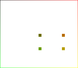
Displace the four corners of a central block:
%IMG7%magick ^
  %SRC% ^
  -shave 1x1 ^
  -alpha transparent ^
  -bordercolor gray(50%%) -border 1 ^
  -set page %%[fx:w*0.4]+%%[fx:h*0.4] ^
  ( -clone 0 ^
    -crop 1x1+%%[fx:w*0.4]+%%[fx:h*0.4] ^
    -alpha opaque ^
    -fill gray(40%%) -colorize 100 ^
  ) ^
  ( -clone 0 ^
    -crop 1x1+%%[fx:w*0.7]+%%[fx:h*0.4] ^
    -alpha opaque ^
    -fill gray(40%%) -colorize 100 ^
  ) ^
  ( -clone 0 ^
    -crop 1x1+%%[fx:w*0.4]+%%[fx:h*0.6] ^
    -alpha opaque ^
    -fill gray(40%%) -colorize 100 ^
  ) ^
  ( -clone 0 ^
    -crop 1x1+%%[fx:w*0.7]+%%[fx:h*0.6] ^
    -alpha opaque ^
    -fill gray(40%%) -colorize 100 ^
  ) ^
  -background None ^
  -layers merge ^
  pop_rmap3.png
|

|
call %PICTBAT%relaxFillMS ^ pop_rmap3.png . . %THRESH% %NUM_ITER% |

|
%IMG7%magick ^ %SRC% ^ pop_rmap3_rfms.png ^ -compose Displace -composite ^ pop_rm3.png |
|
Again, this doesn't work well. Try larger rectangles.
set SW=10
set SH=10

%IMG7%magick ^
  %SRC% ^
  -shave 1x1 ^
  -alpha transparent ^
  -bordercolor gray(50%%) -border 1 ^
  ( -clone 0 ^
    -crop %SW%x%SH%+%%[fx:w*0.5]+%%[fx:h*0.5] ^
    -alpha opaque ^
    -fill gray(40%%) -colorize 100 ^
  ) ^
  ( -clone 0 ^
    -crop %SW%x%SH%+%%[fx:w*0.8]+%%[fx:h*0.5] ^
    -alpha opaque ^
    -fill gray(40%%) -colorize 100 ^
  ) ^
  ( -clone 0 ^
    -crop %SW%x%SH%+%%[fx:w*0.5]+%%[fx:h*0.7] ^
    -alpha opaque ^
    -fill gray(40%%) -colorize 100 ^
  ) ^
  ( -clone 0 ^
    -crop %SW%x%SH%+%%[fx:w*0.8]+%%[fx:h*0.7] ^
    -alpha opaque ^
    -fill gray(40%%) -colorize 100 ^
  ) ^
  -background None ^
+write info: ^
  -layers merge ^
  pop_rmap4.png
|

|
set rfCOMP_METRIC=PAE set THRESH=1e-4 set NUM_ITER=1000 call %PICTBAT%relaxFillMS ^ pop_rmap4.png . . %THRESH% %NUM_ITER% |
|
%IMG7%magick ^ %SRC% ^ pop_rmap4_rfms.png ^ -compose Displace -composite ^ pop_rm4.png |
|
It would be cute to allow constrained movement. For example, we might allow pixels at the left and right sides to move vertically but not horizontally.
For convenience, .bat scripts are also available in a single zip file. See Zipped BAT files.
rem Moves one point, while pinning all edge pixels.
rem See pinorpush.htm#move1pnt

rem %1 input image
rem %2 output
rem %3 X1xY1 move colour from this location
rem %4 X2xY2 move colour to this location
rem %5 optional process to apply to the gradient

@if "%1"=="" findstr /B "rem @rem" %~f0 & exit /B 1

@setlocal enabledelayedexpansion

rem @call echoOffSave

call %PICTBAT%setInOut %1 m1pe

if not "%2"=="" set OUTFILE=%2

set sXY1=%3
if "%sXY1%"=="." set sXY1=
if "%sXY1%"=="" set sXY1=65cx55c

set sXY2=%4
if "%sXY2%"=="." set sXY2=
if "%sXY2%"=="" set sXY2=40cx45c

set sProcGrad=%~5

echo sProcGrad is [%sProcGrad%]

for /F "usebackq" %%A in (`%IMG7%magick ^
  %INFILE% -format "WW=%%w\nHH=%%h\n" ^
  info:`) do set %%A

call parseXxY2 !WW! !HH! xy1 %sXY1%
call parseXxY2 !WW! !HH! xy2 %sXY2%


echo xy1: %xy1_X%,%xy1_Y%
echo xy2: %xy2_X%,%xy2_Y%

%IMG7%magick ^
  %INFILE% +write mpr:INP ^
  -fill White -colorize 100 ^
  -virtual-pixel Black ^
  -distort DePolar -1,0,%xy2_X%,%xy2_Y% ^
  -set option:MYSIZE %%wx%%h ^
  ( -size %%[MYSIZE] ^
    gradient:Black-White ^
  ) ^
  ( -clone 0 ^
    -crop 0x+0+1 +repage ^
    -scale "x1^!" ^
    -scale "%%[MYSIZE]^!" ^
  ) ^
  -delete 0 ^
  -compose DivideSrc -composite ^
  -clamp ^
  -virtual-pixel Edge ^
  -distort Polar -1,0,%xy2_X%,%xy2_Y% ^
  -negate ^
  %sProcGrad% ^
  -write mpr:GRAD +delete ^
  mpr:INP ^
  -sparse-color Bilinear ^
0,0,#000,^
%%[fx:w-1],0,#f00,^
0,%%[fx:h-1],#0f0,^
%%[fx:w-1],%%[fx:h-1],#ff0 ^
  +write mpr:IDENT_MAP ^
  ( +clone ^
  -channel R ^
  -evaluate pow ^
    %%[fx:log(%xy1_X%/(w-1))/log(%xy2_X%/(w-1))] ^
  -channel G ^
  -evaluate pow ^
    %%[fx:log(%xy1_Y%/(h-1))/log(%xy2_Y%/(h-1))] ^
  +channel ^
  ) ^
  +write mpr:MOVE_MAP ^
  mpr:GRAD ^
  -alpha off ^
  -compose Over -composite ^
  +write mpr:BLND_MAP ^
  mpr:INP ^
  +swap ^
  -compose Distort -composite ^
  %OUTFILE%

if ERRORLEVEL 1 exit /B 1

call echoRestore

@endlocal & set m1peOUTFILE=%OUTFILE%
All images on this page were created by the commands shown, using:
%IMG7%magick -version
Version: ImageMagick 7.1.1-15 Q16-HDRI x64 a0a5f3d:20230730 https://imagemagick.org
Copyright: (C) 1999 ImageMagick Studio LLC
License: https://imagemagick.org/script/license.php
Features: Cipher DPC HDRI OpenCL OpenMP(2.0)
Delegates (built-in): bzlib cairo freetype gslib heic jng jp2 jpeg jxl lcms lqr lzma openexr pangocairo png ps raqm raw rsvg tiff webp xml zip zlib
Compiler: Visual Studio 2022 (193532217)
To improve internet download speeds, some images may have been automatically converted (by ImageMagick, of course) from PNG or TIFF or MIFF to JPG.
Source file for this web page is pinorpush.h1. To re-create this web page, run "procH1 pinorpush".
This page, including the images, is my copyright. Anyone is permitted to use or adapt any of the code, scripts or images for any purpose, including commercial use.
Anyone is permitted to re-publish this page, but only for non-commercial use.
Anyone is permitted to link to this page, including for commercial use.
Page version v1.0 18-November-2016.
Page created 18-Aug-2023 14:01:08.
Copyright © 2023 Alan Gibson.