snibgo's ImageMagick pages
Overlapping photographs
Techniques such as Gaussian Pyramid Searches and Minimum Error Boundary Cut are useful for stitching panorama photographs.
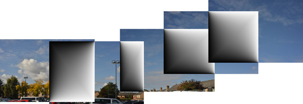
Joiners (David Hockney):
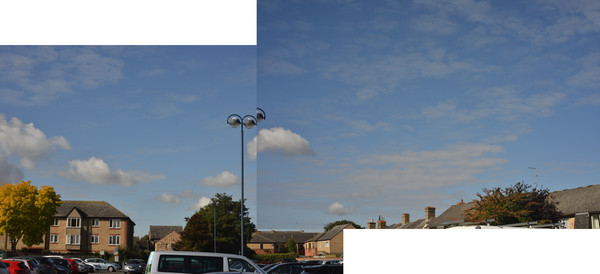
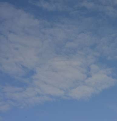
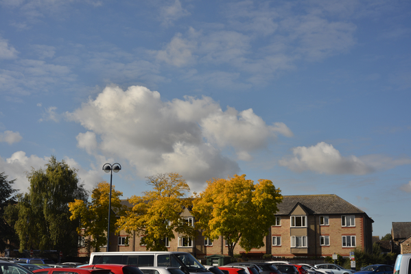
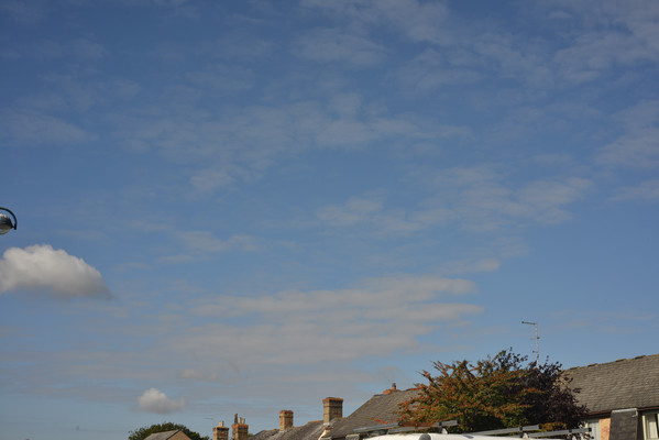
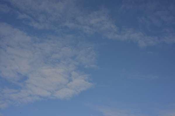
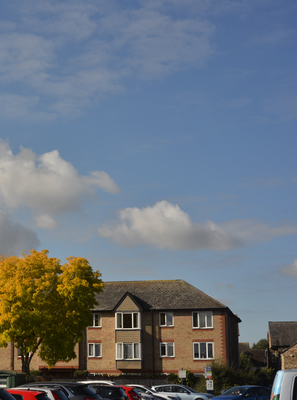
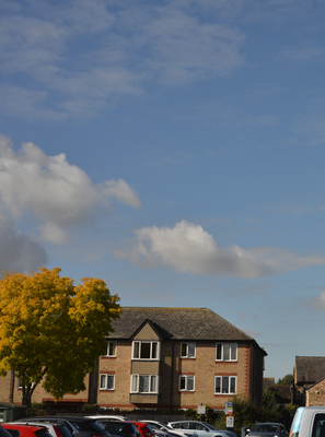
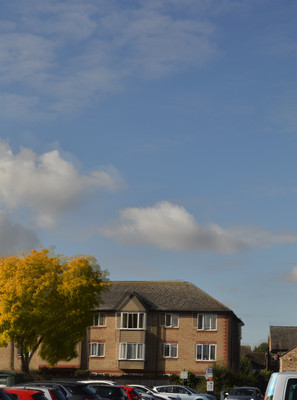
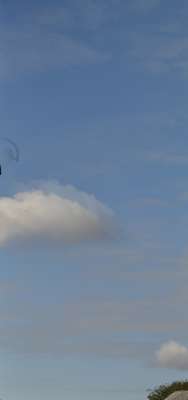
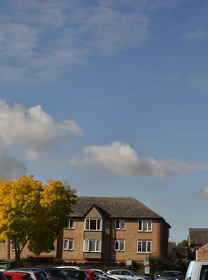
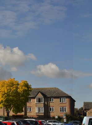
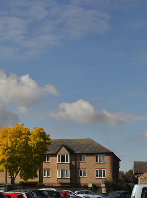
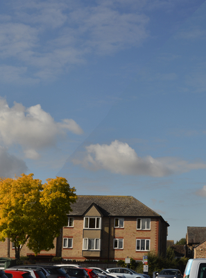
Suppose we have two or more hand-held photographs, taken from roughly the same position at roughly the same time, with arbitrary camera rotation between the photos, so some subject matter occurs on pairs of photos. In each pair, we want one photo to be placed on top of the other with no geometric distortion of either photo. What is a good (x,y) offset so the images join? How can we combine the photos?
- Some cameras can automatically stitch photos.
- Hugin toolset.
-
Microsoft ICE: fast, powerful and simple to use, but inflexible.
- Adobe probably have tools for this.
This page considers some aspects of the problem.
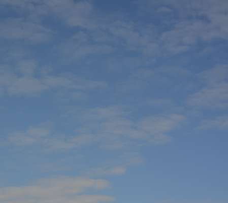
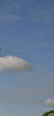
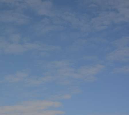
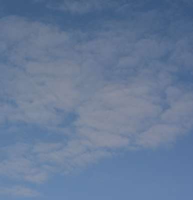
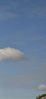
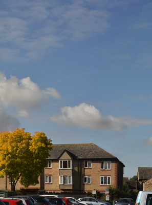
All work on this page is performed on full-size camera images, about 7500x5000 pixels. The results are shrunk and converted to JPG for this web page.
The camera was hand-held. Auto-exposure was used, so the exposure for overlapping parts of the photos varies slightly.
As a rule of thumb, when taking photos for panorama, I try to have at least 50% overlap. This means after taking one photo, I move an object at the edge of the viewfinder to the centre, but no further. (Alternatively, I move the object at the centre no further than the edge of the viewfinder.) By default, the script is slightly more relaxed, setting the search window to 66%, i.e. it assumes the overlap is at least 33%. I was careless, and yawed the camera too far between the second and third photos, creating only about 25% overlap. By default, the script would fail to align those photos, so I need to use the third parameter to set a wider search window.
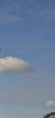
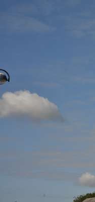
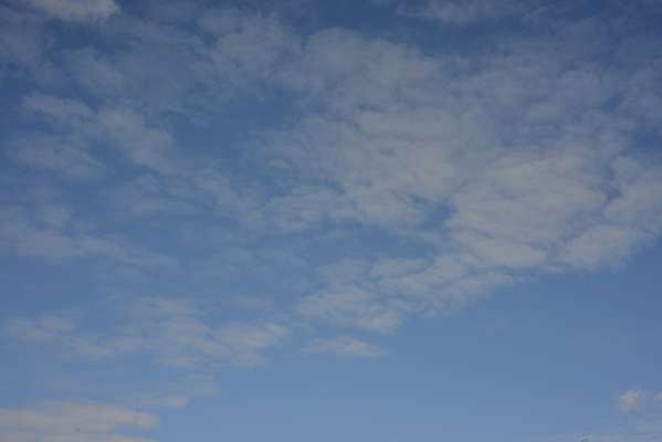
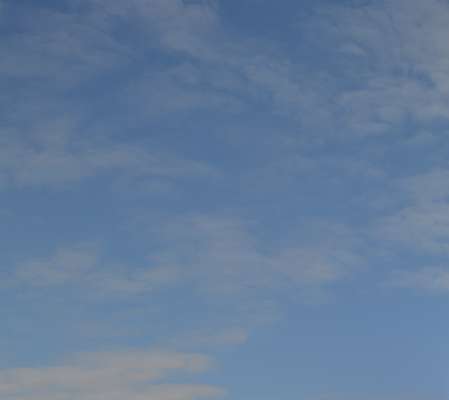
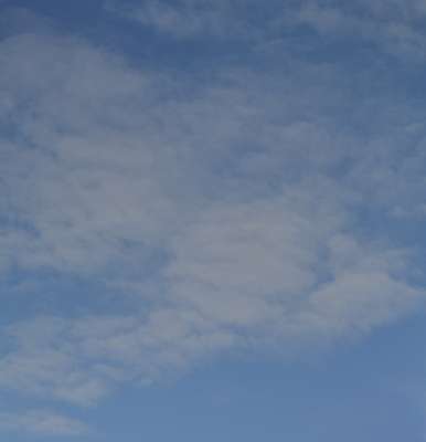
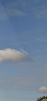
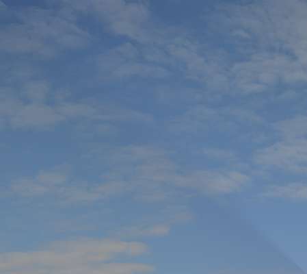
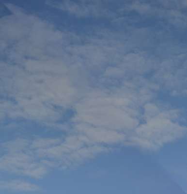
Successful stitching of difficult subjects like clouds need plenty overlap between photos, and a small search window to discourage false matches. They also need a larger value for pyMIN_BLK_WH, eg 25 instead of the more usual 10.
set WEB_SIZE=-resize 600x400
set SRCDIR=\pictures\20151008\

set SRC1=%SRCDIR%AGA_2595.JPG

%IM%convert %SRC1% %WEB_SIZE% op_src1_sm.miff
|
|
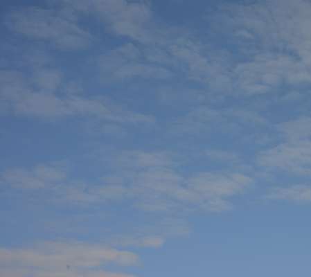
set SRC2=%SRCDIR%AGA_2596.JPG

%IM%convert %SRC2% %WEB_SIZE% op_src2_sm.miff
|

|
set SRC3=%SRCDIR%AGA_2597.JPG

%IM%convert %SRC3% %WEB_SIZE% op_src3_sm.miff
|
|
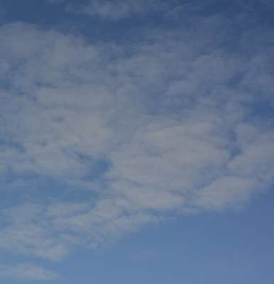
set SRC4=%SRCDIR%AGA_2598.JPG

%IM%convert %SRC4% %WEB_SIZE% op_src4_sm.miff
|
|
set SRC5=%SRCDIR%AGA_2599.JPG

%IM%convert %SRC5% %WEB_SIZE% op_src5_sm.miff

goto skip2
|
|
The first problem is: which photos overlap which other photos, and what are the best alignments (aka registration)? We are trying to find which area on photo A matches which area on photo B.
On other pages, I show methods for
Simple alignment by matching areas and
Alignment by matching points. An alternative technique is
Alignment by brute force, which we will use here.
[[ An area from photo A overlaps the same-size area on photo B. We can crop to the overlaps and compare them. RMSE (root mean squared error) gives us a measure of how closely the overlap areas match. We can try every possible overlapping offset to find the one with the best (smallest) RMSE. See the script
alignBF.bat.
If the two images have WxH pixels, there are 4WH-2H-2W+1 possible offset positions. When W=7500 and H=5000, this is about 150 million offsets. As most comparisons will take more than a second, alignment by brute force is not feasible on the full-size photos. ]]
If the photos were printed on transparent sheets, we could place both on a lightbox and slide them around until we found the best overlap. This will involve a translation and rotation blah. We would start by looking at major features: a big green blob in photo A is similar to a blob in photo B, so we try that position and see if finer details match up.
This suggests an alternative: use the brute-force alignment technique on simplified versions of the two photos. This gives an approximate alignment, reducing the search stage needed for the next search, which operates on versions that are less simplified. For the "simplified versions", we use Gaussian pyramids, which are successive resizes of an image. (For more detail, including the mkGausPyr.bat script, see
Multi-scale pyramids.)
This is practically the same technique as shown in
Searching an image.
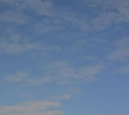
A difficulty arises: blue sky in one photograph closely matches blue sky in another.
Goal: layout (n) photos so they match up.
A matrix of scores tells us which photos to stitch together. [Sadly, no it doesn't. ]
Make a Gaussian pyramid from each image, telling the script to make no octaves with fewer than 25x25 pixels. On my laptop, this takes about 8 seconds per image. The tiff files are 360 MB each.
With set pyWR_VAR=1 we write the variables about one pyramid to a "_blk.lis" file. It doesn't matter which pyramid we choose for this, as the values are the same for each.
set pyMIN_BLK_WH=25
set pyPREFIX=op_pyr_

if not exist op_g1.tiff call %PICTBAT%mkGausPyr %SRC1% op_g1.tiff
if not exist op_g2.tiff call %PICTBAT%mkGausPyr %SRC2% op_g2.tiff
if not exist op_g3.tiff call %PICTBAT%mkGausPyr %SRC3% op_g3.tiff
if not exist op_g4.tiff call %PICTBAT%mkGausPyr %SRC4% op_g4.tiff

set pyWR_VAR=1
call %PICTBAT%mkGausPyr %SRC5% op_g5.tiff
set pyWR_VAR=

set pyMIN_BLK_WH=
A typical tiff file is:
%IM%identify op_g1.tiff
op_g1.tiff[0] TIFF 7360x4912 7360x4912+0+0 16-bit sRGB 361.7MB 0.000u 0:00.000
op_g1.tiff[1] TIFF 3680x2456 3680x2456+0+0 16-bit sRGB 361.7MB 0.000u 0:00.000
op_g1.tiff[2] TIFF 1840x1228 1840x1228+0+0 16-bit sRGB 361.7MB 0.000u 0:00.000
op_g1.tiff[3] TIFF 920x614 920x614+0+0 16-bit sRGB 361.7MB 0.000u 0:00.000
op_g1.tiff[4] TIFF 460x307 460x307+0+0 16-bit sRGB 361.7MB 0.000u 0:00.000
op_g1.tiff[5] TIFF 230x154 230x154+0+0 16-bit sRGB 361.7MB 0.000u 0:00.000
op_g1.tiff[6] TIFF 115x77 115x77+0+0 16-bit sRGB 361.7MB 0.000u 0:00.000
op_g1.tiff[7] TIFF 58x38 58x38+0+0 16-bit sRGB 361.7MB 0.000u 0:00.000
op_g1.tiff[8] TIFF 7360x4912 7360x4912+0+0 16-bit Grayscale Gray 361.7MB 0.000u 0:00.000
The structure of the others is the same. There are ten octaves, plus a final difference. As level 0 is the same size as the source, the final difference should be zero.
The script
alignGausPyr.bat finds the alignment of two pyramids, using brute force at each level. First, it finds the alignment of the top levels of two pyramids, and assumes it is correct plus or minus one pixel. This is used to limit the range of positions searched in the next level down. It continues finding alignments at corresponding levels down to level 0. We have used the default block factor of 2, so the comparisons are up to plus or minus 2 pixels in either direction, making 25 comparisons at each level after the top.
call %PICTBAT%alignGausPyr op_g1.tiff op_g2.tiff
Finding the alignment of these pyramids, for 7500x5000 images, takes about ten seconds on my laptop.
The output CSV file contains data on the alignment found for level 0:
- The best RMSE score.
- The x- and y-offset of the second image with respect to the first.
- The width and height of the overlapping areas.
- The top-left position of the overlap within the first image.
- The top-left position of the overlap within the second image.
0.105041,3474,-882,3886,4030,3474,0,0,882
The script
rdAgpDf.bat reads this data, and also keeps a running cumulative of the offsets.
call %PICTBAT%rdAgpDf 2
Because level 0 is the same size as the source images, we can use use the data directly:
|
Create a montage.
%IM%convert ^
  ( %SRC1% ) ^
  ( %SRC2% -repage +%OV_X.2%+%OV_Y.2% ) ^
  -layers merge +repage ^
  +depth ^
  %WEB_SIZE% ^
  op_1-2_rs_sm.png
|
|
|
Create crops of both overlaps.
%IM%convert ^
  %SRC1% ^
  -crop %OV_W.2%x%OV_H.2%+%OV_X1.2%+%OV_Y1.2% ^
  +repage ^
  +depth ^
  +write op_1-2_ra.tiff ^
  %WEB_SIZE% ^
  op_1-2_ra_sm.png

%IM%convert ^
  %SRC2% ^
  -crop %OV_W.2%x%OV_H.2%+%OV_X2.2%+%OV_Y2.2% ^
  +repage ^
  +depth ^
  +write op_1-2_rb.tiff ^
  %WEB_SIZE% ^
  op_1-2_rb_sm.png
|
|
We can continue for the other pairs.
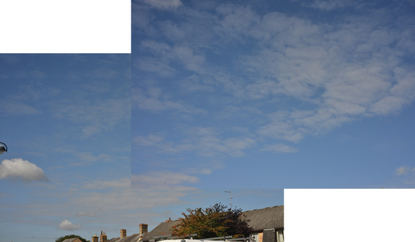
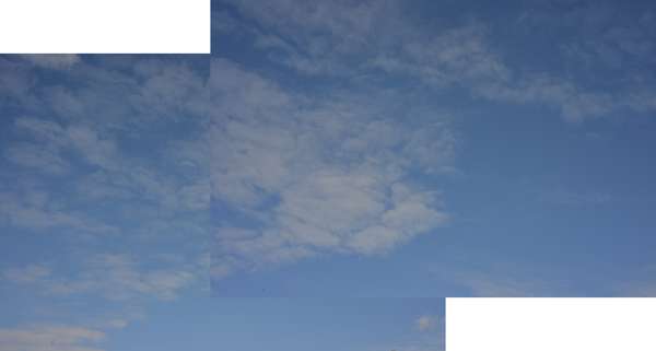
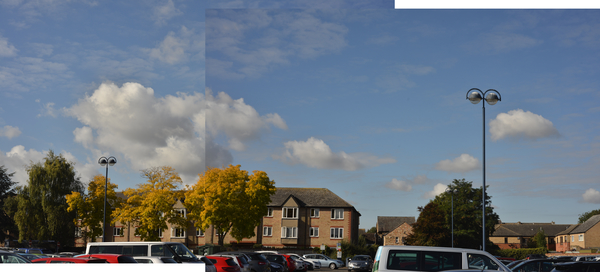
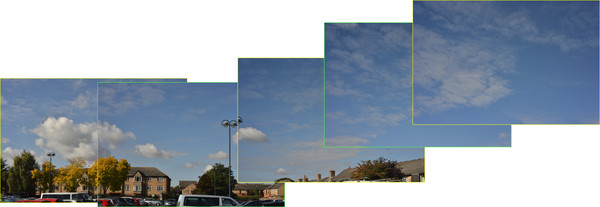
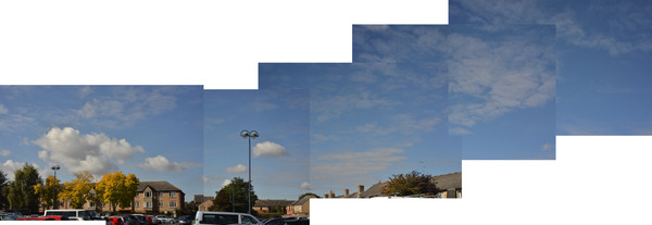
From the cumulative offsets, we create the montage of all the sources.
%IM%convert ^
  ( %SRC1% ) ^
  ( %SRC2% -repage +%OV_X_CUM.2%+%OV_Y_CUM.2% ) ^
  ( %SRC3% -repage +%OV_X_CUM.3%+%OV_Y_CUM.3% ) ^
  ( %SRC4% -repage +%OV_X_CUM.4%+%OV_Y_CUM.4% ) ^
  ( %SRC5% -repage +%OV_X_CUM.5%+%OV_Y_CUM.5% ) ^
  -layers merge +repage ^
  -format %%wx%%h +write info: ^
  %WEB_SIZE% ^
  op_15_rs_sm.png
23561x8146
|

|
The camera tilt varies between these photos. Blah.
Match histograms of overlaps. Either make all photos match a "master" that is assumed correct, or assume they are all correct, and blend the overlaps.
When photos are offset in both directions, blending isn't a good solution; there will always be discontinuity or a sudden change at two corners of the overlap. But the two-axis fan might work.
1. Starting with a base photo assumed correct, use the two overlaps to get a clut that will equalise histograms, cumulate this through the other overlaps. Adjust all photos to match the base photo, and create blended overlaps.
Or 2. Don't adjust any photos. Instead, modify just the overlaps.
Make a clut that would make histogram of SRC1 match histogram of SRC2:
[[Junk starts here:
The above is junk blah.]]
Find the gain and bias to match each overlap A with B:
call %PICTBAT%colGainBias op_1-2_ra.tiff op_1-2_rb.tiff op 1-2
call %PICTBAT%colGainBias op_2-3_ra.tiff op_2-3_rb.tiff op 2-3
call %PICTBAT%colGainBias op_3-4_ra.tiff op_3-4_rb.tiff op 3-4
call %PICTBAT%colGainBias op_4-5_ra.tiff op_4-5_rb.tiff op 4-5

The cgb environment variables are:
set cgb
cgbBiasB.1-2=-0.0186281
cgbBiasB.2-3=-0.10785
cgbBiasB.3-4=-0.0214292
cgbBiasB.4-5=0.128234
cgbBiasG.1-2=-0.0178838
cgbBiasG.2-3=0.00112519
cgbBiasG.3-4=0.0501276
cgbBiasG.4-5=0.119164
cgbBiasR.1-2=-0.0041191
cgbBiasR.2-3=-0.0156215
cgbBiasR.3-4=0.0316134
cgbBiasR.4-5=0.059379
cgbGainB.1-2=1.00442
cgbGainB.2-3=1.13743
cgbGainB.3-4=1.07594
cgbGainB.4-5=0.817169
cgbGainG.1-2=1.01185
cgbGainG.2-3=0.96019
cgbGainG.3-4=0.929041
cgbGainG.4-5=0.779405
cgbGainR.1-2=0.979016
cgbGainR.2-3=0.986685
cgbGainR.3-4=0.956437
cgbGainR.4-5=0.880672
cgbMEAN.0=0.387788
cgbMEAN.1=0.464308
cgbMEAN.2=0.576039
cgbMEAN.3=0.400893
cgbMEAN.4=0.481048
cgbMEAN.5=0.598955
cgbPREF=op
cgbSD.0=0.0772978
cgbSD.1=0.0649529
cgbSD.2=0.0534795
cgbSD.3=0.068074
cgbSD.4=0.0506246
cgbSD.5=0.0437018
cgbSUFF=4-5
|
To demonstrate colour discontinuity,
we place half the overlap from SRC2
over the overlap from SRC1.
%IMDEV%convert ^
  op_1-2_ra.tiff ^
  ( op_1-2_rb.tiff -gravity East -crop 50%%x100%%+0+0 ) ^
  -layers merge +repage ^
  %WEB_SIZE% ^
  op_1-2_noncld.png
The colour discontinuity is clear.
|

|
|
The same, but adjusting the overlap from SRC1.
%IMDEV%convert ^
  ( op_cgb_1-2.tiff ) ^
  ( op_1-2_rb.tiff -gravity East -crop 50%%x100%%+0+0 ) ^
  -layers merge +repage ^
  %WEB_SIZE% ^
  op_1-2_cld.png
The colour discontinuity has been removed.
|

|
Where the edge is one photo is laid on another photo, the boundary is fairly obvious from colour and geometric discontinuities. We might do nothing about this, or we might make a feature of it, or reduce or eliminate it.
- No processing, as shown above
- Highlight the edges
- Alpha-blend across the overlaps
- Feather the edges
- Minimum error column cut
- Minimum error boundary cut
-
set HIGHLIGHT=-shave 15x15 -border 15

set Hi1=-bordercolor #ff0 %HIGHLIGHT%
set Hi2=-bordercolor #4f4 %HIGHLIGHT%

%IM%convert ^
  ( %SRC1% %Hi1% ) ^
  ( %SRC2% %Hi2% -repage +%OV_X_CUM.2%+%OV_Y_CUM.2% ) ^
  ( %SRC3% %Hi1% -repage +%OV_X_CUM.3%+%OV_Y_CUM.3% ) ^
  ( %SRC4% %Hi2% -repage +%OV_X_CUM.4%+%OV_Y_CUM.4% ) ^
  ( %SRC5% %Hi1% -repage +%OV_X_CUM.5%+%OV_Y_CUM.5% ) ^
  -layers merge +repage ^
  +repage ^
  %WEB_SIZE% ^
  op_15_bord_sm.png
|
|
If we have composited one photo over another, we can then compose an image over the overlap area. This extra image can be created from some processing of the two cropped areas.
Here, the script
mkOvMasks.bat creates a mask image for each overlap. The mask is black where it is adjacent to the first image of the pair, and white where it is adjacent to the second image of the pair. By merging the mask with the second image of each pair, we visually check the mask dimensions, position and polarity.
for /F %%L in (ov_var.lis) do set %%L

call %PICTBAT%mkOvMasks 2 5

%IM%convert ^
  ( %SRC1% ) ^
  ( %SRC2% ^
    ( ov_mask_1-2.png -repage +%OV_X2.2%+%OV_Y2.2% ) ^
    -layers merge +repage -repage +%OV_X_CUM.2%+%OV_Y_CUM.2% ^
  ) ^
  ( %SRC3% ^
    ( ov_mask_2-3.png -repage +%OV_X2.3%+%OV_Y2.3% ) ^
    -layers merge +repage -repage +%OV_X_CUM.3%+%OV_Y_CUM.3% ^
  ) ^
  ( %SRC4% ^
    ( ov_mask_3-4.png -repage +%OV_X2.4%+%OV_Y2.4% ) ^
    -layers merge +repage -repage +%OV_X_CUM.4%+%OV_Y_CUM.4% ^
  ) ^
  ( %SRC5% ^
    ( ov_mask_4-5.png -repage +%OV_X2.5%+%OV_Y2.5% ) ^
    -layers merge +repage -repage +%OV_X_CUM.5%+%OV_Y_CUM.5% ^
  ) ^
  -layers merge +repage ^
  %WEB_SIZE% ^
  op_15_msk_sm.png
|
|
Above, we made for each overlap pair a version of the A side that is colour-adjusted to match the B side. We now use masks to blend these into new overlaps.
for /L %%N in (2,1,5) do (
  set /A Nm1=%%N-1

  %IM%convert ^
    op_!Nm1!-%%N_ra.tiff ^
    op_cgb_!Nm1!-%%N.tiff ^
    ov_mask_!Nm1!-%%N.png ^
    -alpha off -composite ^
    +write op_!Nm1!-%%N_cgbbl.tiff ^
    %WEB_SIZE% ^
    op_!Nm1!-%%N_cgbbl_sm.png
)
The colour-blended overlaps look like this:


We make a montage using these colour-blended overlaps:
%IM%convert ^
  ( %SRC1% ) ^
  ( %SRC2% ^
    ( op_1-2_cgbbl.tiff -repage +%OV_X2.2%+%OV_Y2.2% ) ^
    -layers merge +repage -repage +%OV_X_CUM.2%+%OV_Y_CUM.2% ^
  ) ^
  ( %SRC3% ^
    ( op_2-3_cgbbl.tiff -repage +%OV_X2.3%+%OV_Y2.3% ) ^
    -layers merge +repage -repage +%OV_X_CUM.3%+%OV_Y_CUM.3% ^
  ) ^
  ( %SRC4% ^
    ( op_3-4_cgbbl.tiff -repage +%OV_X2.4%+%OV_Y2.4% ) ^
    -layers merge +repage -repage +%OV_X_CUM.4%+%OV_Y_CUM.4% ^
  ) ^
  ( %SRC5% ^
    ( op_4-5_cgbbl.tiff -repage +%OV_X2.5%+%OV_Y2.5% ) ^
    -layers merge +repage -repage +%OV_X_CUM.5%+%OV_Y_CUM.5% ^
  ) ^
  -layers merge +repage ^
  +write op_15_cgbbl.tiff ^
  %WEB_SIZE% ^
  op_15_cgbbl_sm.png
|
|
The result is crap blah.
The masks can be used for simple alpha blending.
for /L %%N in (2,1,5) do (
  set /A Nm1=%%N-1

  %IM%convert ^
    op_!Nm1!-%%N_ra_sm.png ^
    op_!Nm1!-%%N_rb_sm.png ^
    ^( ov_mask_!Nm1!-%%N.png %WEB_SIZE% ^) ^
    -composite ^
    %WEB_SIZE% ^
    op_bl_!Nm1!-%%N_sm.png
)
The blended overlaps look like this:
Ghosting is obvious and horrible. We could reduce the area in which blending occurs:
for /L %%N in (2,1,5) do (
  set /A Nm1=%%N-1

  %IM%convert ^
    op_!Nm1!-%%N_ra_sm.png ^
    op_!Nm1!-%%N_rb_sm.png ^
    ^( ov_mask_!Nm1!-%%N.png -level 45%%,55%% %WEB_SIZE% ^) ^
    -composite ^
    %WEB_SIZE% ^
    op_bl2_!Nm1!-%%N_sm.png
)
Ghosting isn't as bad, and the result may be acceptable.
for /F %%L in (ov_var.lis) do set %%L

set DIST=100

for /L %%N in (2,1,5) do (

  set /A Nm1=%%N-1

  %IM%convert ^
    ov_mask_!Nm1!-%%N.png ^
    ^( +clone ^
      -shave %DIST% ^
      -fill Black -colorize 100 ^
      -bordercolor White -border %DIST% -morphology Distance "Euclidean:7,%DIST%^!" ^
      -negate ^
    ^) ^
    -compose Plus -composite ^
    %WEB_SIZE% ^
    op_feath_!Nm1!-%%N_sm.png
)


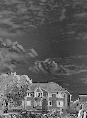
The square of the difference between a pair of overlaps measures the error in the overlap. Where this is black, there is zero error. Lighter portions show more error. For example, the overlap between SRC1 and SRC2:
:skip

%IM%convert ^
  op_1-2_ra.tiff ^
  op_1-2_rb.tiff ^
  -compose Difference -composite ^
  -grayscale RMS ^
  -evaluate Pow 2 ^
  +depth ^
  +write op_1-2_err.tiff ^
  %WEB_SIZE% ^
  -auto-level -auto-gamma ^
  op_1-2_err_sm.png
|
|
(I consider a difference in one channel that is numerically equal to a difference in another channel to be equally visible, hence -grayscale RMS. The -auto-level -auto-gamma is only for visual clarity on this web page.)
Then we find the column (or row) with the smallest mean.
for /F "usebackq delims=, " %%L in (`%IMDEV%convert ^
  op_1-2_err.tiff ^
  -scale "x1^!" ^
  -negate ^
  -process onelightest ^
  NULL: 2^>^&1`) do set VCUT=%%L

echo VCUT=%VCUT%
VCUT=2799
If the photos were vertically aligned, this make a reasonable cut-line. If we want to create the boundary between the two overlaps by a vertical line, this is the place that makes the join the least obvious.
%IM%convert ^
  op_1-2_ra.tiff ^
  ( op_1-2_rb.tiff -crop +%VCUT%+0 ) ^
  -layers merge +repage ^
  %WEB_SIZE% ^
  op_15_vcut_sm.png
|
|
This is the least-obvious vertical cut, but we can clearly see it in the sky.
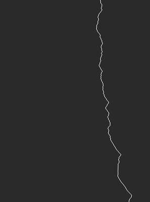
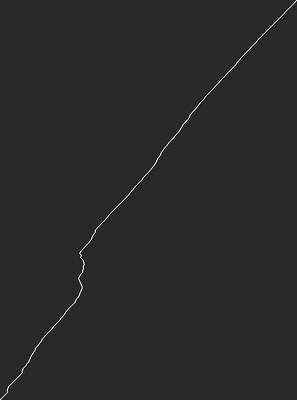
Process module: darkest path finds the path from top to bottom that has the smallest sum. Rule of thumb: always use HDRI for this.
%IMDEV%convert ^
  op_1-2_err.tiff ^
  -process darkestpath ^
  +write op_1-2_dp.tiff ^
  %WEB_SIZE% ^
  -auto-level ^
  op_1-2_dp_sm.png
|
|
%IM%convert ^
  op_1-2_ra.tiff ^
  op_1-2_rb.tiff ^
  ( op_1-2_dp.tiff ^
    -fill White -draw "color 0,0 floodfill" ^
    -negate ^
  ) ^
  -alpha off -composite ^
  +write op_15_dpcut.tiff ^
  %WEB_SIZE% ^
  op_15_dpcut_sm.png
|
|
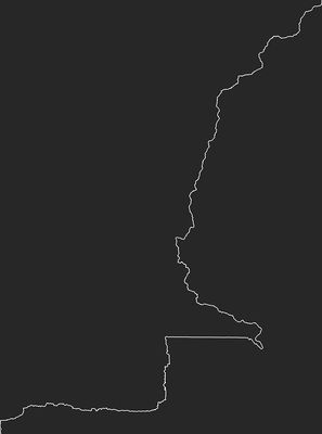
For this application, we want the mimumum error boundary that starts runs between opposite corners. We influence darkestpath by replacing the top and bottom rows with white, except for black pixels at the corners. Multiplying the white by 10,000 ensures that a path through a "super-white" pixel will not be very dark, and such a path is unlikely to be the darkest.
%IMDEV%convert ^
  op_1-2_err.tiff ^
  -shave 0x1 ^
  ( -clone 0 ^
    -crop x1+0+0 +repage ^
    -fill White -colorize 100 ^
    -fill Black -draw "point 0,0" ^
    -evaluate Multiply 10000 ^
  ) ^
  ( -clone 1 -flop ) ^
  -insert 0 ^
  -append ^
  -process darkestpath ^
  +write op_1-2_dp.tiff ^
  %WEB_SIZE% ^
  -auto-level ^
  op_1-2_dp2_sm.png
|
|
%IM%convert ^
  op_1-2_ra.tiff ^
  op_1-2_rb.tiff ^
  ( op_1-2_dp.tiff ^
    -fill White -draw "color 0,0 floodfill" ^
    -negate ^
  ) ^
  -alpha off -composite ^
  +write op_15_dp2cut.tiff ^
  %WEB_SIZE% ^
  op_15_dp2cut_sm.png
|
|
This boundary is more visible than the previous one made with the more direct path.
The darkestpath will not be closer to the horizontal than 45°. If the aspect ratio changes so the "portrait" format approaches square, the path becomes more constrained to approach a 45° line. A "landscape" format should be rotated by 90°.
An alternative method for corner-to-corner paths is with "-process darkestpntpnt", specifying the coordinates of the corners. The "p" suffix removes the need to find the dimensions.
:skip2

rem goto skipdpp
%IMDEV%convert ^
  op_1-2_err.tiff ^
  -process 'darkestpntpnt s 1p,0 e 0,1p v' ^
  +write op_1-2_dpp.tiff ^
  %WEB_SIZE% ^
  -auto-level ^
  op_1-2_dpp_sm.png

:skipdpp
|
|
%IM%convert ^
  op_1-2_ra.tiff ^
  op_1-2_rb.tiff ^
  ( op_1-2_dpp.tiff ^
    -fill White -draw "color 0,0 floodfill" ^
    -negate ^
  ) ^
  -alpha off -composite ^
  +write op_15_dppcut.tiff ^
  %WEB_SIZE% ^
  op_15_dppcut_sm.png
|
|
The visual result is far better. Viewing the 3533x4752 result full-size, I can't see the join, even when I know exactly where it is. Sadly, darkestpntpnt for this op_1-2_err.tiff takes 50 minutes.
If the overlap is the opposite polarity, the path should span the other two corners.
If colours have been adjusted, the error image will be different, so the darkest paths will also be different. Blah At each overlap, we take ???
Remove large files we no longer need.
rem del ov_mask_*.png
For convenience, .bat scripts are also available in a single zip file. See
Zipped BAT files.
The script uses utility programs cGroup.exe and cJoin.exe. I don't provide source or binaries of these. Here, they reduce the data file to contain only the line with the lowest RMSE score. The work could be done by sorting numerically, in reverse, and finding the first line.
rem Find x-y alignment of two same-size images %1 and %2 by brute force comparison.
@rem We find the position that scores the best RMSE.
@rem Fairly fast when WW*HH is small, or search space is small.
@rem
@rem Optional:
@rem   %2 is width of both
@rem   %3 is height of both
@rem   %5,%6 top-left to try
@rem   %7,%8 botton-right to try
@rem
@rem Returns name of a file containing CSV data.
@rem If best is at an extreme, probably dodgy.
@rem
@rem Updated:
@rem   15 May 2016 use %IML% for @script.

@if "%2"=="" findstr /B "rem @rem" %~f0 & exit /B 1

@setlocal enabledelayedexpansion

@call echoOffSave

call %PICTBAT%setInOut %1 abf


set SCR_FILE=%sioCODE%.scr
set DATA_FILE=%sioCODE%_data.csv
set DATA_FILE2=%sioCODE%_data2.csv
set DATA_FILE3=%sioCODE%_data3.csv

set SRC1=%1
set SRC2=%2

set WW=%3
set HH=%4

if "%WW%"=="." set WW=
if "%HH%"=="." set HH=

set FIND_DIMS=0
if "%WW%"=="" set FIND_DIMS=1
if "%HH%"=="" set FIND_DIMS=1

if %FIND_DIMS%==1 for /F "usebackq" %%L in (`%IM%identify ^
  -format "WW=%%w\nHH=%%h" ^
  %SRC1%`) do set %%L

if "%WW%"=="" (
  echo %0: can't identify SRC1 [%SRC1%]
  exit /B 1
)

echo %SRC1% %SRC2% >%SCR_FILE%

set /A WWm1=%WW%-1
set /A HHm1=%HH%-1

set FirstX=%5
set FirstY=%6
set LastX=%7
set LastY=%8

if "%FirstX%"=="." set /A FirstX=
if "%FirstY%"=="." set /A FirstY=
if "%LastX%"=="." set /A LastX=
if "%LastY%"=="." set /A LastY=

if "%FirstX%"=="" set /A FirstX=-%WWm1%
if "%FirstY%"=="" set /A FirstY=-%HHm1%

if "%LastX%"=="" set /A LastX=%WWm1%
if "%LastY%"=="" set /A LastY=%HHm1%

rem First or Last might be beyond -+WWm1 etc.

if %FirstX% LSS -%WWm1% set /A FirstX=-%WWm1%
if %FirstY% LSS -%HHm1% set /A FirstY=-%HHm1%
if %LastX% GTR %WWm1% set /A LastX=%WWm1%
if %LastY% GTR %HHm1% set /A LastY=%HHm1%

echo %~n0: WWm1=%WWm1% HHm1=%HHm1% FirstX=%FirstX% FirstY=%FirstY% LastX=%LastX% LastY=%LastY%

set MIN_COMP=999

rem Optional -auto-level -auto-gamma  to each crop?
for /L %%y in (%FirstY%,1,%LastY%) do (

  if %%y GEQ 0 (
    set /A H=%HH%-%%y
    set /A Y1=%%y
    set /A Y2=0
  ) else (
    set /A H=%HH%+%%y
    set /A Y1=0
    set /A Y2=-%%y
  )

  for /L %%x in (%FirstX%,1,%LastX%) do (

    if %%x GEQ 0 (
      set /A W=%WW%-%%x
      set /A X1=%%x
      set /A X2=0
    ) else (
      set /A W=%WW%+%%x
      set /A X1=0
      set /A X2=-%%x
    )

    ( echo ^( -clone 0-1
      echo   ^( -clone 0 -crop !W!x!H!+!X1!+!Y1! +repage -auto-level ^)
      echo   ^( -clone 1 -crop !W!x!H!+!X2!+!Y2! +repage -auto-level ^)
      echo   -delete 0-1
      echo   -metric RMSE -compare
      echo   -format "%%[distortion],%%x,%%y,!W!,!H!,!X1!,!Y1!,!X2!,!Y2!\n"
      echo   +write info:
      echo   +delete
      echo ^)
    )
  )
)>>%SCR_FILE%

rem type %SCR_FILE%

%IML%convert @%SCR_FILE% NULL: >%DATA_FILE%
if ERRORLEVEL 1 exit /B 1

cGroup /p0 /i%DATA_FILE% /n0 /o%DATA_FILE2% /u
cJoin  /p0 /i%DATA_FILE2%,%DATA_FILE% /o%DATA_FILE3% /k0 /K0 /n /c2

for /F "tokens=1-9 delims=," %%A in (%DATA_FILE3%) do (
  set COMP=%%A
  set BESTX=%%B
  set BESTY=%%C
  set W=%%D
  set H=%%E
  set X1=%%F
  set Y1=%%G
  set X2=%%H
  set Y2=%%I
)

if "%COMP%"=="" exit /B 1

set DODGY=1
if not "%BESTX%"=="%FirstX%" if not "%BESTX%"=="%LastX%" if not "%BESTY%"=="%FirstY%" if not "%BESTY%"=="%LastY%" set DODGY=0

echo %~n0: %COMP% %X% %Y% BESTX=%BESTX% BESTY=%BESTY% X1=%X1% Y1=%Y1% X2=%X2% Y2=%Y2%


call echoRestore

@endlocal & set abfDATAFILE=%DATA_FILE3%& set abfDODGY=%DODGY%
rem Find translation-only alignment of two Gaussian pyramids %1 and %2 with same structure.
rem Assumes %pyPREFIX% is the prefix of an appropriate blk.lis file.
@rem
@rem Optional:
@rem   %3 Factor for initial search window eg 0.66.

@if "%2"=="" findstr /B "rem @rem" %~f0 & exit /B 1

@setlocal enabledelayedexpansion

@call echoOffSave

call %PICTBAT%setInOut %1 agp


set SRC1=%1
set SRC2=%2

set SRCH_WIND=%3
if "%SRCH_WIND%"=="." set SRCH_WIND=
if "%SRCH_WIND%"=="" set SRCH_WIND=0.6667


if "%pyPREFIX%"=="" (
  echo %0: pyPREFIX not set
  exit /B 1
)

for /F "tokens=*" %%L in (%pyPREFIX%blk.lis) do set %%L

if "%NUM_OCTAVES%"=="" (
  echo %0: NUM_OCTAVES not set in %pyPREFIX%blk.lis
  exit /B 1
)

set /A iOct=%NUM_OCTAVES%-1


for /F "usebackq" %%L in (`%IM%identify ^
  -format "SrchW=%%[fx:int(!N_BLK_W.%iOct%!*%SRCH_WIND%+0.5)]\nSrchH=%%[fx:int(!N_BLK_H.%iOct%!*%SRCH_WIND%+0.5)]" ^
  xc:`) do set %%L


rem Get dims multiplied by magic overlap factor for first search.

call %PICTBAT%alignBF ^
  %SRC1%[%iOct%] %SRC2%[%iOct%] ^
  !N_BLK_W.%iOct%! !N_BLK_H.%iOct%! -%SrchW% -%SrchH% %SrchW% %SrchH%

set DODGY=%abfDODGY%

call :ReadBlkLis


for /L %%i in (%iOct%,-1,1) do (

  echo %~n0: BESTX=!BESTX! BESTY=!BESTY!
  echo %~n0: N_BLK_W.%%i=!N_BLK_W.%%i!
  echo %~n0: N_BLK_H.%%i=!N_BLK_H.%%i!

  set /A PrevOct=%%i-1

  call :GetPrev %%i !PrevOct!

  echo %~n0: FirstX=!FirstX! FirstY=!FirstY! LastX=!LastX! LastY=!LastY!

  call %PICTBAT%alignBF ^
    %SRC1%[!PrevOct!] %SRC2%[!PrevOct!] ^
    !BW! !BH! !FirstX! !FirstY! !LastX! !LastY!

  if "!abfDODGY!"=="1" set DODGY=1

  call :ReadBlkLis
)

echo %~n0: COMP=%COMP% abfDATAFILE=%abfDATAFILE%

call echoRestore

@endlocal & set agpDATAFILE=%abfDATAFILE%& set agpDODGY=%DODGY%

exit /B 0

::---------------- Subroutines ----------------
:ReadBlkLis

  rem type %abfDATAFILE%

  for /F "tokens=1-9 delims=," %%A in (!abfDATAFILE!) do (
    set COMP=%%A
    set BESTX=%%B
    set BESTY=%%C
    set W=%%D
    set H=%%E
    set X1=%%F
    set Y1=%%G
    set X2=%%H
    set Y2=%%I
  )
  echo %~n0: !COMP! !X! !Y! X1=!X1! Y1=!Y1! X2=!X2! Y2=!Y2!

  exit /B

:GetPrev
  echo %~n0: N_BLK_W.%2=!N_BLK_W.%2!
  echo %~n0: N_BLK_H.%2=!N_BLK_H.%2!

  set /A BW=!N_BLK_W.%2!
  set /A BH=!N_BLK_H.%2!
  set /A FirstX=^(!BESTX!-1^)*!N_BLK_W.%2!/!N_BLK_W.%1!
  set /A FirstY=^(!BESTY!-1^)*!N_BLK_H.%2!/!N_BLK_H.%1!
  set /A LastX=^(!BESTX!+1^)*!N_BLK_W.%2!/!N_BLK_W.%1!
  set /A LastY=^(!BESTY!+1^)*!N_BLK_H.%2!/!N_BLK_H.%1!

  exit /B
set N=%1
if "%N%"=="" set N=1

for /F "tokens=1-9 delims=," %%A in (%agpDATAFILE%) do (
  set OV_COMP.%N%=%%A
  set OV_X.%N%=%%B
  set OV_Y.%N%=%%C
  set OV_W.%N%=%%D
  set OV_H.%N%=%%E
  set OV_X1.%N%=%%F
  set OV_Y1.%N%=%%G
  set OV_X2.%N%=%%H
  set OV_Y2.%N%=%%I
)

set /A Nm1=%N%-1
set OV_X_CUM.%N%=!OV_X.%N%!
set OV_Y_CUM.%N%=!OV_Y.%N%!

if not "!OV_X_CUM.%Nm1%!"=="" set /A OV_X_CUM.%N%+=!OV_X_CUM.%Nm1%!
if not "!OV_Y_CUM.%Nm1%!"=="" set /A OV_Y_CUM.%N%+=!OV_Y_CUM.%Nm1%!

echo %~n0: !OV_X_CUM.%N%! !OV_Y_CUM.%N%!
For mkFanComp2A.bat, see
Composite compositions.
rem Make overlay masks.
@rem %1 is first mask [default 2]
@rem %2 is last mask [eg 5]
@rem Assumes ov_ variables have been set

@if "%2"=="" findstr /B "rem @rem" %~f0 & exit /B 1

@setlocal

call echoOffSave

call %PICTBAT%setInOut %1 mom


set nFirst=%1
set nLast=%2

if "!OV_W.%nLast%!"=="" (
  echo %0: OV_W.%nLast% not set
  exit /B 1
)

set ov

for /L %%N in (%nFirst%,1,%nLast%) do (

  set /A Nm1=%%N-1

  call %PICTBAT%mkFanComp2A !OV_W.%%N! !OV_H.%%N! ov_mask_!Nm1!-%%N.png

  set /A SIGN_D=!OV_X.%%N!*!OV_Y.%%N!

  if !SIGN_D! LSS 0 %IM%convert ov_mask_!Nm1!-%%N.png -flip ov_mask_!Nm1!-%%N.png

  if !OV_X.%%N! LSS 0 %IM%convert ov_mask_!Nm1!-%%N.png -negate ov_mask_!Nm1!-%%N.png
)


call echoRestore & set bpOUTFILE=%OUTFILE%
rem Makes a clut that would transform the histogram of %1 to match the histogram of %2.
rem Writes the output to %3.

%IMDEV%convert ^
  %1 ^
  ( -clone 0 ^
-format "%%[fx:minima.r] %%[fx:minima.g] %%[fx:minima.b]\n" +write info: ^
-format "%%[fx:maxima.r] %%[fx:maxima.g] %%[fx:maxima.b]\n" +write info: ^
    -process 'mkhisto cumul norm' ^
+write moc_a.png ^
  ) ^
  ( %2 ^
-format "%%[fx:minima.r] %%[fx:minima.g] %%[fx:minima.b]\n" +write info: ^
-format "%%[fx:maxima.r] %%[fx:maxima.g] %%[fx:maxima.b]\n" +write info: ^
    -process 'mkhisto cumul norm' ^
+write moc_b.png ^
    -process 'mkhisto cumul norm' ^
+write moc_c.png ^
  ) ^
  -delete 0 ^
  -clut ^
+write moc_d.png ^
  +depth ^
  %3

call %PICTBAT%graphLineCol moc_a.png
call %PICTBAT%graphLineCol moc_b.png
call %PICTBAT%graphLineCol moc_c.png
call %PICTBAT%graphLineCol moc_d.png
All images on this page were created by the commands shown, using:
%IM%identify -version
Version: ImageMagick 6.9.5-3 Q16 x86 2016-07-22 http://www.imagemagick.org
Copyright: Copyright (C) 1999-2015 ImageMagick Studio LLC
License: http://www.imagemagick.org/script/license.php
Visual C++: 180040629
Features: Cipher DPC Modules OpenMP
Delegates (built-in): bzlib cairo flif freetype jng jp2 jpeg lcms lqr openexr pangocairo png ps rsvg tiff webp xml zlib
To improve internet download speeds, some images may have been automatically converted (by ImageMagick, of course) from PNG to JPG.
Source file for this web page is overphot.h1. To re-create this web page, run "procH1 overphot".
This page, including the images, is my copyright. Anyone is permitted to use or adapt any of the code, scripts or images for any purpose, including commercial use.
Anyone is permitted to re-publish this page, but only for non-commercial use.
Anyone is permitted to link to this page, including for commercial use.
Page version v1.0 13-October-2015.
Page created 15-Oct-2016 13:19:35.
Copyright © 2016 Alan Gibson.