set GRC_SRC=grc_src1.png

%IMG7%magick ^
  -size 600x400 xc: ^
  -sparse-color bilinear ^
    0,0,gray30,599,0,gray33,0,399,black,599,399,white ^
  -alpha off ^
  %GRC_SRC%

A grayscale gradient image can be made more readable by showing contour lines, or lines perpendicular to contours.
A contour connects adjacent pixels that have the same value. They are very easy to construct. If the image represents a landscape with lightness representing heights, then contour lines would look like those on a map.
With more difficulty, we can draw lines perpendicular to the contours. These represent paths water would take flowing down the hilly landscape.
Commands and scripts on this page use my "cumulhisto" process module. For source code and installation instructions, see Process modules: cumulhisto.
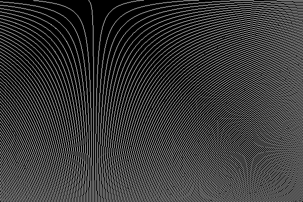
Make an image with smoothly changing gray values.
set GRC_SRC=grc_src1.png
%IMG7%magick ^
-size 600x400 xc: ^
-sparse-color bilinear ^
0,0,gray30,599,0,gray33,0,399,black,599,399,white ^
-alpha off ^
%GRC_SRC%
|
|
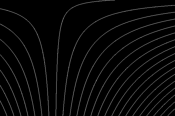
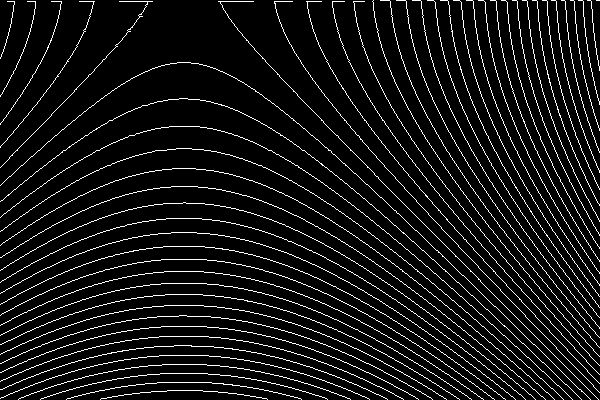
We can draw contours that follow lines of constant tone. These are like contours on a map that join points of the same height.
set FREQm1=49

%IMG7%magick ^
  %GRC_SRC% ^
  ( -size 1x500 gradient: -rotate 90 ^
    -duplicate %FREQm1% +append +repage ) ^
  -clut ^
  -morphology edgein diamond:1 ^
  -threshold 40%% ^
  grc_src1_sc.png
|

|
Contour lines are close together where the tone changes rapidly; the gradient is steep. They are far apart where the tone changes slowly; the gradient is shallow.
The contour scale is constant. There is one contour line per 1/50th of the interval between black and white.
The result is aliased (jagged), even before the threshold.
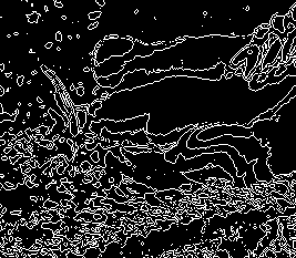
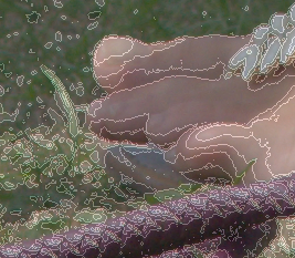
We can apply the same technique to photographs:
%IMG7%magick ^
  toes.png ^
  ( -size 1x500 gradient: -rotate 90 ^
    -duplicate 7 +append +repage ) ^
  -clut ^
  -morphology edgein diamond:1 ^
  -threshold 40%% ^
  grc_toes_sc.png

%IMG7%magick ^
  toes.png ^
  ( grc_toes_sc.png ^
    -alpha set ^
    -channel alpha ^
    -evaluate set 25%% ^
    +channel ^
  ) ^
  -composite ^
  grc_toes_sc_o.png
|
|
We can vary the contour scale. First, create a gradient image. The auto-levelled version is purely for display, not for further processing.
%IMG7%magick ^
  %GRC_SRC% ^
  -statistic Gradient 10x10 ^
  +write grc_s1_gr.png ^
  -format "min=%%[fx:minima] max=%%[fx:maxima]\n" ^
  +write info: ^
  -auto-level ^
  grc_s1_gr_al.png
min=0.000549325 max=0.0298161 |

|
The maximum gradient across a 10x10 square is about 3%. If the frequency was 33, we would have an interval of about 10 pixels between contours.
To get the same interval of 10 pixels/contour, a 2% gradient would need a frequency of 50, and a 1% gradient would need a frequency of 100.
We can partition the image into areas where the gradient is closest to 0%, 1%, 2% or 4%. We do this by mapping to a 4x1 image with those percentages of gray, and creating one mask per area.
The script mMapMasks.bat makes N map masks from an image and a Nx1 map. Each mask is the same size as the image. The i-th mask is white where the image pixel is closer to the i-th pixel in a map than to other pixels in the map.
The script also creates cumulative masks. The i-th cumulative mask is white where the image pixel is closer to the i-th or lower pixel in a map than to higher pixels in the map. There are (N-1) cumulative masks.
%IMG7%magick ^
  xc:black xc:gray(1%%) xc:gray(2%%) xc:gray(4%%) +append +repage ^
  grc_map1.png

call %PICTBAT%mMapMasks grc_s1_gr.png grc_map1.png grc_s1_msk_.png
The four masks are:


We can verify that these masks give exact coverage with no overlap. The mean of all the masks should be a single colour.
%IMG7%magick ^
  grc_s1_msk*.png ^
  -evaluate-sequence Mean ^
  -unique-colors ^
  txt:
# ImageMagick pixel enumeration: 3,1,0,255,gray
0,0: (73)  #494949  gray(28.5714%)
1,0: (109)  #6D6D6D  gray(42.8571%)
2,0: (146)  #929292  gray(57.1429%)
The three cumulative masks are:


The second is white except for a small black triangle in the bottom-right corner. The third is entirely white.
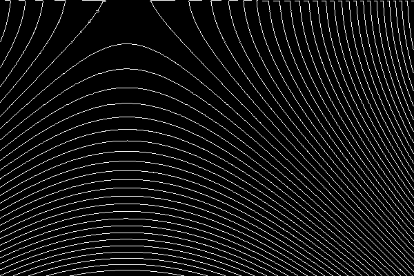
We create four images with the required contour frequencies:
set FREQm1=199

%IMG7%magick ^
  %GRC_SRC% ^
  ( -size 1x500 gradient: -rotate 90 ^
    -duplicate %FREQm1% +append +repage ) ^
  -clut ^
  -morphology edgein diamond:1 ^
  -threshold 40%% ^
  grc_s1_f1.png
|
|
set FREQm1=99

%IMG7%magick ^
  %GRC_SRC% ^
  ( -size 1x500 gradient: -rotate 90 ^
    -duplicate %FREQm1% +append +repage ) ^
  -clut ^
  -morphology edgein diamond:1 ^
  -threshold 40%% ^
  grc_s1_f2.png
|
|
set FREQm1=49

%IMG7%magick ^
  %GRC_SRC% ^
  ( -size 1x500 gradient: -rotate 90 ^
    -duplicate %FREQm1% +append +repage ) ^
  -clut ^
  -morphology edgein diamond:1 ^
  -threshold 40%% ^
  grc_s1_f3.png
|

|
set FREQm1=24

%IMG7%magick ^
  %GRC_SRC% ^
  ( -size 1x500 gradient: -rotate 90 ^
    -duplicate %FREQm1% +append +repage ) ^
  -clut ^
  -morphology edgein diamond:1 ^
  -threshold 40%% ^
  grc_s1_f4.png
|
|
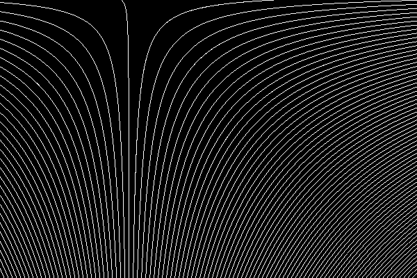
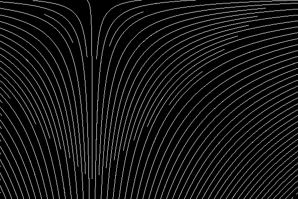
We create a merged image from the contour images and masks.
%IMG7%magick ^ grc_s1_f1.png ^ grc_s1_f2.png ^ grc_s1_msk_2.png ^ -composite ^ grc_s1_f3.png ^ grc_s1_msk_3.png ^ -composite ^ grc_s1_f4.png ^ grc_s1_msk_4.png ^ -composite ^ grc_s1_mrgd.png |
|
Note that mask grc_s1_msk_1.png isn't used.
Note that doubling frequency gives continuous contours.
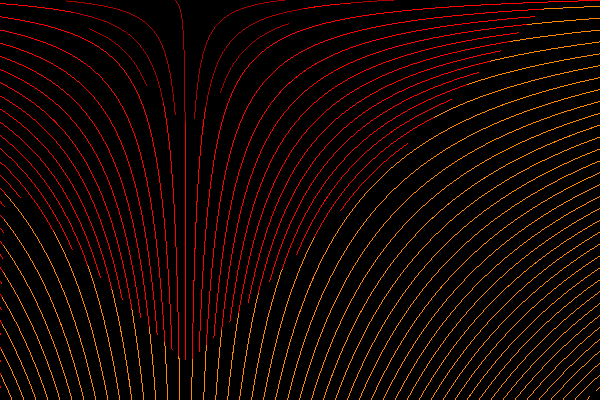
The contours are white so we can easily colour them:
%IMG7%magick ^
  ( grc_s1_f1.png ^
    -set colorspace sRGB ^
    -fill #a00 -opaque #fff ) ^
  ( grc_s1_f2.png ^
    -set colorspace sRGB ^
    -fill #f00 -opaque #fff ) ^
  grc_s1_msk_2.png ^
  -composite ^
  ( grc_s1_f3.png ^
    -set colorspace sRGB ^
    -fill #f80 -opaque #fff ) ^
  grc_s1_msk_3.png ^
  -composite ^
  ( grc_s1_f4.png ^
    -set colorspace sRGB ^
    -fill #ff0 -opaque #fff ) ^
  grc_s1_msk_4.png ^
  -composite ^
  grc_s1_mrgdc.png
|
|
But layering in the opposite order makes the colouring more logical.
Here, we use the cumulative masks.
%IMG7%magick ^
  ( grc_s1_f1.png ^
    -set colorspace sRGB ^
    -fill #a00 -opaque #fff ) ^
  ( grc_s1_f2.png ^
    -set colorspace sRGB ^
    -transparent #000 -fill #f00 -opaque #fff ) ^
  grc_s1_msk_c_2.png ^
  -composite ^
  ( grc_s1_f3.png ^
    -set colorspace sRGB ^
    -transparent #000 -fill #f80 -opaque #fff ) ^
  grc_s1_msk_c_3.png ^
  -composite ^
  ( grc_s1_f4.png ^
    -set colorspace sRGB ^
    -transparent #000 -fill #ff0 -opaque #fff ) ^
  grc_s1_msk_c_4.png ^
  -composite ^
  grc_s1_mrgdc2.png
|
|
We might want to draw lines perpendicular to contours. This is the direction rainwater would take after falling in a hillside.
-statistic Gradient would give the magnitude of the gradient but not the direction. But we need both magnitude and direction.
We can calculate the x-component and y-component of the gradient separately, putting these in the red and green channels. We calculate the blue channel as the magnitude of the gradient: m=sqrt(x^2+y^2). The values are offset by 0.5, so a pixel value of 50% in a channel means zero gradient in that direction. Magnitude is always positive so the blue channel is always at least 50%.
The following code does this, using a Sobel convolution.
set AUTO=-auto-level -auto-gamma
set AUTO=

%IMG7%magick ^
  %GRC_SRC% ^
  -alpha off ^
  -define convolve:scale="50%%^!" -bias 50%% ^
  ( -clone 0 ^
    -morphology Convolve Sobel:0 ^
    -separate -evaluate-sequence Max ^
    %SIG% ^
    %AUTO% ^
    +write h.png ^
  ) ^
  ( -clone 0 ^
    -morphology Convolve Sobel:90 ^
    -separate -evaluate-sequence Max ^
    %SIG% ^
    %AUTO% ^
    +write v.png ^
  ) ^
  ( -clone 0 ^
    -fill Black -colorize 100 ^
  ) ^
  -delete 0 ^
  -combine ^
  -channel B ^
  -fx "hypot(u.r-0.5,u.g-0.5)+0.5" ^
  -fx "u.b==0?1:u.b" ^
  +channel ^
  +depth ^
  grc_pc0.png

call %PICTBAT%autoLevMid grc_pc0.png


The autoLevMid.bat script increases contrast, like -auto-level, but around the 50% level so that remains at 50%. We can see that the red channel increases from left to right, while the green channel increases from top to bottom.
From the image grc_pc0.png, at every pixel we know the differential of the horizontal and vertical components of the gradient. To find the perpendicular to the gradient, we simply swap the components.
Once we have a differential gradient, we can apply the inverse process (integration) to get a gradient. However, the Sobel technique above is not easily reversible. Instead, we can take simple differences horizontally and vertically.
%IMG7%magick ^
  %GRC_SRC% ^
  ( -clone 0 ^
    ( -clone 0 ^
      ( -clone 0 ) ^
      -geometry +1+0 ^
      -compose Over -composite ^
    ) ^
    -geometry +0+0 ^
    -compose Mathematics -define compose:args=0,-1,1,0.5 -composite ^
  ) ^
  ( -clone 0 ^
    ( -clone 0 ^
      ( -clone 0 ) ^
      -geometry +0+1 ^
      -compose Over -composite ^
    ) ^
    -geometry +0+0 ^
    -compose Mathematics -define compose:args=0,-1,1,0.5 -composite ^
  ) ^
  ( -clone 0 ^
    -fill gray50 -colorize 100 ) ^
  -delete 0 ^
  -combine ^
  -channel B ^
  -fx "hypot(u.r-0.5,u.g-0.5)+0.5" ^
  -fx "u.b==0?1:u.b" ^
  +channel ^
  +depth ^
  grc_pc1.png

call %PICTBAT%autoLevMid grc_pc1.png
We show grc_pc1.png and the autoLevMid version:


How close is the simple difference gradient to the Sobel version? I compare the _alm versions of each.
%IMG7%magick compare -metric RMSE grc_pc0_alm.png grc_pc1_alm.png NULL:

cmd /c exit /B 0
402.36 (0.00613962)
For this artificial image, they are very close. I expect the Sobel version would smooth out very fine detail.
For convenience, we make a script, diffGrad.bat, from the long magick command. This records the differential of the horizontal and vertical components of the gradient. It also sets the environment variable dgTOP_LEFT.
call %PICTBAT%diffGrad ^
  %GRC_SRC% grc_src1_dg.png

echo %dgTOP_LEFT%
30.1960784313725 |

|
The script diffGrad.bat has created a differential gradient file. This section applies the inverse process, an integration, to make a gradient from a differential.
The red channel records the gradient horizontally, and the green channel record the gradient vertically. To reconstitute any pixel, we need the original value of one pixel, such as at coordinate (0,0). From that pixel we can walk in horizontal and vertical steps as required to reach the destination point, summing the gradients from red or green as we go.
We can cumulate in the horizontal direction with -process cumulhisto, starting with zeros in the left-most column:
%IM7DEV%magick ^
  grc_pc1.png ^
  -separate ^
  ( -clone 0 -evaluate Subtract 50%% -process cumulhisto +write r.png ) ^
  -delete 0-2 ^
  grc_recon_h.png

But the left-most column shouldn't be zeros. The left-most column can be calculated as the (0,0) pixel, cumulated downwards by the green (vertical) channel. This is equivalent to cumulating from zero, then adding the (0,0) pixel.
First, we find the top-left value:
for /F "usebackq" %%C in (`%IMG7%magick ^
  %GRC_SRC% ^
  -precision 15 ^
  -format "TOP_LEFT=%%[fx:100*p{0,0}.r]" ^
  info:`) do set %%C

echo %TOP_LEFT%
30.1960784313725
Then we cumulate:
%IM7DEV%magick ^
  grc_pc1.png ^
  -separate ^
  ( -clone 1 -crop 1x400+0+0 +repage +write v0.png ^
    -rotate -90 ^
    -evaluate Subtract 50%% -process cumulhisto ^
    -evaluate Add %TOP_LEFT%%% ^
    -rotate 90 +write v.png ^
    -scale "600x400^!" ^
  ) ^
  -delete 0-2 ^
  grc_recon_v.png

We can add recon_h and recon_v:
%IMG7%magick ^
  grc_recon_h.png ^
  grc_recon_v.png ^
  -compose Plus -composite ^
  grc_recon.png

How accurate is the reconstruction?
%IMG7%magick compare -metric RMSE %GRC_SRC% grc_recon.png NULL:

cmd /c exit /B 0
270.785 (0.00413192)
It is very accurate. So we can do the round trip from an input image to its gradient, and back (though we need to know the top-left pixel of the input).
The input is grayscale, and needs two channels to record the gradient. If the input was RGB we would need six channels.
The three magick commands can be combined and built into a script, invDiffGrad.bat.
call %PICTBAT%invDiffGrad ^ grc_src1_dg.png %dgTOP_LEFT% grc_recon2.png |

|
How accurate is this reconstruction?
%IMG7%magick compare -metric RMSE %GRC_SRC% grc_recon2.png NULL:

cmd /c exit /B 0
327.727 (0.00500079)
This is accurate.
If we take the inverse of the difference gradient, but swapping the horizontal and vertical vectors and negating one of them, the gradient at every pixel will be perpendicular to the original direction. If the horizontal vector is negated, the new direction gradient will be the old direction rotated by 90° clockwise. If the vertical vector is negated, it is rotated 90° anti-clockwise.
The script invDiffGrad.bat does this when idgROT is set to +1 or -1. We create both versions:
set idgROT=+1 call %PICTBAT%invDiffGrad ^ grc_src1_dg.png %dgTOP_LEFT% grc_clk.png |

|
set idgROT=-1 call %PICTBAT%invDiffGrad ^ grc_src1_dg.png %dgTOP_LEFT% grc_anticlk.png set idgROT= |

|
When rotating, the invDiffGrad script auto-levels the output blah blah. If it didn't do this, pixels might be calculated to be outside the range 0 to 100%. Hence, the top-left pixel will no longer have the original value. If we are only interested in contours, this doesn't matter.
The two rotations are negatives of each other; a "hill" in one is a "dip" in the other. If we add the two images, all pixels should be virtually the same value.
%IMG7%magick ^
  grc_clk.png ^
  grc_anticlk.png ^
  -compose Plus -composite ^
  -format "MINIMA=%%[fx:minima]\nMAXIMA=%%[fx:maxima]" ^
  info:
MINIMA=0.717388
MAXIMA=0.717403
FUTURE: A process module that does an auto-level but doesn't shift a certain percentage of quantum would be useful.
From these two rotations, we can create contour images.
set FREQm1=49

%IMG7%magick ^
  grc_clk.png ^
  -auto-level ^
  ( -size 1x500 gradient: -rotate 90 ^
    -duplicate %FREQm1% +append +repage ) ^
  -clut ^
  -morphology edgein diamond:1 ^
  -threshold 40%% ^
  grc_clk_sc.png
|
|
set FREQm1=49

%IMG7%magick ^
  grc_anticlk.png ^
  -auto-level ^
  ( -size 1x500 gradient: -rotate 90 ^
    -duplicate %FREQm1% +append +repage ) ^
  -clut ^
  -morphology edgein diamond:1 ^
  -threshold 40%% ^
  grc_anticlk_sc.png
|
|
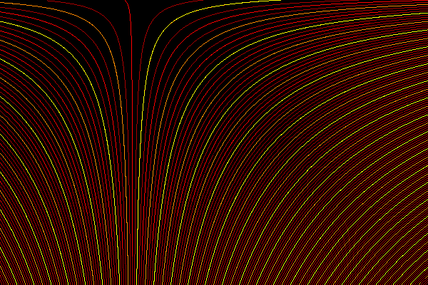
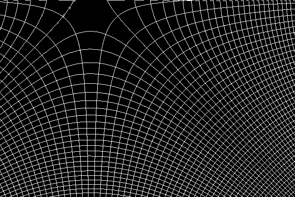
As expected, the contours are almost identical.
The first two rows, and some other rows, are not wonderful. This occurs when the row contains repeated values, which in turn occurs when the source image contains repeated values in columns. The process works best when the input contains values that continually vary.
We can overlay this on the original contours as a visual check that they are perpendicular.
%IMG7%magick ^
  grc_src1_sc.png ^
  ( grc_anticlk_sc.png ^
    -transparent Black ^
  ) ^
  -composite ^
  grc_sc_comp.png
|
|
For convenience, .bat scripts are also available in a single zip file. See Zipped BAT files.
rem Given image %1
rem and %2 image, size Nx1,
rem makes N masks, each the size of %1, white where %1 pixel is closest to that %2 pixel.
rem Also makes cumulative masks.
@rem
@rem Optional %3: base name for masks. They will be numbered 1 to N.
@rem
@rem Returns mmmNumMasks number of masks created.
@rem
@rem This is the opposite to deMapMasks.bat.
@rem
@rem Updated:
@rem   26-May-2016 for v7.
@rem   7-August-2022 for IM v7.

rem We could have another map file to colour the contours.
rem We could dilate the lines.


@if "%2"=="" findstr /B "rem @rem" %~f0 & exit /B 1

@setlocal

@call echoOffSave

call %PICTBAT%setInOut %1 mmm

set MAP_FILE=%2

set MASK_DD=
set MASK_PREF=
set MASK_EXT=
if not "%3"=="" (
  set MASK_DD=%~dp3
  set MASK_PREF=%~n3
  set MASK_EXT=%~x3
)

if "%MASK_PREF%"=="" set MASK_PREF=%sioCODE%
if "%MASK_EXT%"=="" set MASK_EXT=.png

set TMP_FILE=%TEMP%\%MASK_PREF%_tmp%MASK_EXT%
set SCR_FILE=%TEMP%\%MASK_PREF%_scr.bat
set CUMUL_SCR_FILE=%TEMP%\%MASK_PREF%_cumul_scr.bat

set HH=
set NumMasks=
for /F "usebackq" %%L in (`%IMG7%magick identify ^
  -format "HH=%%h\nNumMasks=%%w" ^
  %MAP_FILE%`) do set %%L

if not "%HH%"=="1" (
  echo %0: map file [%MAP_FILE%] not height 1
  exit /B 1
)
if "%NumMasks%"=="" exit /B 1

%IMG7%magick %INFILE% +dither -remap %MAP_FILE% %TMP_FILE%
if ERRORLEVEL 1 (
  echo %0: [%1] [%2] convert failed
  exit /B 1
)

echo %IMG7%magick %TMP_FILE% -fill Black -background White >%SCR_FILE%
echo %IMG7%magick -compose Lighten >%CUMUL_SCR_FILE%

set CNT=1
for /F "usebackq skip=1 tokens=6 delims=,:() " %%C in (`%IMG7%magick ^
  %MAP_FILE% ^
  -colorspace sRGB ^
  txt:`) do (
  echo %%C

  set MASK_FILE=%MASK_DD%%MASK_PREF%!CNT!%MASK_EXT%
  set CUMUL_FILE=%MASK_DD%%MASK_PREF%c_!CNT!%MASK_EXT%

  echo ^( +clone -transparent %%C -colorize 100 -flatten +write !MASK_FILE! +delete ^) >>%SCR_FILE%

  echo !MASK_FILE! >>%CUMUL_SCR_FILE%

  if !CNT! GTR 1 (
    echo -composite +write !CUMUL_FILE! >>%CUMUL_SCR_FILE%
  )

  set /A CNT+=1
)

cPrefix /i%SCR_FILE% /r^^
echo NULL: >>%SCR_FILE%
cPrefix /i%CUMUL_SCR_FILE% /r^^
echo NULL: >>%CUMUL_SCR_FILE%

type %SCR_FILE%
call %SCR_FILE%

type %CUMUL_SCR_FILE%
call %CUMUL_SCR_FILE%

call echoRestore

endlocal & set mmmOUTFILE=%OUTFILE%& set mmmNumMasks=%NumMasks%
rem Makes auotolevel version, such that 50% remains at 50%.
rem Output %2 will have 0% or 100%, but generally not both.
rem %3 if not 0, will first add 50% to the image.
@rem
@rem Assumes magick is HDRI.
@rem
@rem Updated:
@rem   25-June-2017 Added "ADDHALF" facility.
@rem   22-July-2022 Upgraded for IM v7.
@rem

@if "%1"=="" findstr /B "rem @rem" %~f0 & exit /B 1

@setlocal

@call echoOffSave

call %PICTBAT%setInOut %1 alm

if not "%2"=="" if not "%2"=="." set OUTFILE=%2

set ADDHALF=%3
if "%ADDHALF%"=="." set ADDHALF=
if "%ADDHALF%"=="" set ADDHALF=0

if "%ADDHALF%"=="0" (
  set sADDHALF=
) else (
  set sADDHALF=-evaluate Add 50%%
)

for /F "usebackq" %%L in (`%IMG7%magick ^
  %INFILE% ^
  %sADDHALF% ^
  -format "dm=%%[fx:abs(minima-0.5)>abs(maxima)?minima:maxima]" ^
  info:`) do set %%L

echo %0: dm=%dm%

for /F "usebackq" %%L in (`%IMG7%magick identify ^
  -format "dm=%%[fx:100*(%dm%>0.5?1-%dm%:%dm%)]" ^
  xc:`) do set %%L

echo %0: dm=%dm%

for /F "usebackq" %%L in (`%IMG7%magick identify ^
  -format "dmo=%%[fx:100-%dm%]" ^
  xc:`) do set %%L

echo %0: dmo=%dmo%

%IMG7%magick ^
  %INFILE% ^
  %sADDHALF% ^
  -level %dm%,%dmo%%% ^
  %OUTFILE%


call echoRestore

endlocal & set almOUTFILE=%OUTFILE%&
@rem See also invDiffGrad.bat.
@rem
@rem Updated:
@rem   6-August-2022 for IM v7
@rem


@if "%1"=="" findstr /B "rem @rem" %~f0 & exit /B 1

@setlocal

@call echoOffSave

call %PICTBAT%setInOut %1 dg

if not "%2"=="" set OUTFILE=%2

set TOP_LEFT=
:: This was %IM16i%convert
::
for /F "usebackq" %%L in (`%IMG7%magick ^
  %INFILE% ^
  -precision 15 ^
  -format "TOP_LEFT=%%[fx:100*p{0,0}.r]" ^
  +write info: ^
  ^( -clone 0 ^
    ^( -clone 0 ^
      ^( -clone 0 ^) ^
      -geometry +1+0 ^
      -compose Over -composite ^
    ^) ^
    -geometry +0+0 ^
    -compose Mathematics -define "compose:args=0,-1,1,0.5" -composite ^
  ^) ^
  ^( -clone 0 ^
    ^( -clone 0 ^
      ^( -clone 0 ^) ^
      -geometry +0+1 ^
      -compose Over -composite ^
    ^) ^
    -geometry +0+0 ^
    -compose Mathematics -define "compose:args=0,-1,1,0.5" -composite ^
  ^) ^
  ^( -clone 0 ^
     -fill gray50 -colorize 100 ^) ^
  -delete 0 ^
  -combine ^
  -channel B ^
  -fx "hypot(u.r-0.5,u.g-0.5)+0.5" ^
  -fx "u.b==0?1:u.b" ^
  +channel ^
  +depth ^
  %OUTFILE%`) do set %%L

if "%TOP_LEFT%"=="" exit /B 1

call echoRestore

endlocal & set dgOUTFILE=%OUTFILE%& set dgTOP_LEFT=%TOP_LEFT%
@rem See also diffGrad.bat.
@rem
@rem Updated:
@rem   6-August-2022 for IM v7
@rem


@if "%2"=="" findstr /B "rem @rem" %~f0 & exit /B 1

@setlocal

@call echoOffSave

call %PICTBAT%setInOut %1 idg

set TOP_LEFT=%2
if "%TOP_LEFT%"=="." set TOP_LEFT=
if "%TOP_LEFT%"=="" set TOP_LEFT=50

if not "%3"=="" set OUTFILE=%3

if "%idgROT%"=="" set idgROT=0

set TMPFILE=%~n1_idg_tmp.miff

rem The rotation is wrong.
rem The red channel has zero in the first column,
rem so can't be cumulated for vertical.

if %idgROT% EQU 0 (
  set CLONE_H=0
  set CLONE_V=1
  set NEG_H=
  set NEG_V=
) else if %idgROT% EQU -1 (
  set CLONE_H=1
  set CLONE_V=0
  set NEG_H=
  set NEG_V=-negate
) else if %idgROT% EQU 1 (
  set CLONE_H=1
  set CLONE_V=0
  set NEG_H=-negate
  set NEG_V=
)

for /F "usebackq" %%L in (`%IMG7%magick identify ^
  -format "WW=%%w\nHH=%%h" %INFILE%`) do set %%L

rem in -crop, +1 is a kludge.

%IM7DEV%magick ^
  "%INFILE%" ^
  -channel RGB -separate +channel ^
  ( -clone %CLONE_H% ^
    %NEG_H% ^
    -evaluate Subtract 50%% ^
    -process cumulhisto ^
  ) ^
  ( -clone %CLONE_V% -crop 1x%HH%+1+0 +repage ^
    %NEG_V% ^
    -rotate -90 ^
    -evaluate Subtract 50%% ^
    -process cumulhisto ^
    -evaluate Add %TOP_LEFT%%% ^
    -rotate 90 ^
    -scale "%WW%x%HH%^!" ^
  ) ^
  -delete 0-2 ^
  -evaluate-sequence Add ^
-format "%%[fx:minima] %%[fx:maxima]" +write info: ^
  -define quantum:format=floating-point -depth 32 ^
  "%TMPFILE%"

call %PICTBAT%shiftNoNeg %TMPFILE% %OUTFILE%


call echoRestore

endlocal & set idgOUTFILE=%OUTFILE%&
rem Given image %1 that may contain negative values,
rem writes output with no negative values.
@rem
@rem Assumes magick has HDRI.
@rem
@rem Updated:
@rem   6-August-2022 for IM v7
@rem

@if "%1"=="" findstr /B "rem @rem" %~f0 & exit /B 1

@setlocal

@call echoOffSave

call %PICTBAT%setInOut %1 snn

if not "%2"=="" set OUTFILE=%2

set MIN_PC=
for /F "usebackq" %%L in (`%IMG7%magick ^
  "%INFILE%" ^
  -format "MIN=%%[fx:minima]\nMIN_PC=%%[fx:(-minima)*100]\nMIN_LSS_Z=%%[fx:minima<0?1:0]\n" ^
  info:`) do set %%L

if "%MIN_PC%"=="" exit /B 1

echo %0: MIN_PC=%MIN_PC%  MIN_LSS_Z=%MIN_LSS_Z%

if "%MIN_LSS_Z%"=="1" (
  set sADD=-evaluate Add %MIN_PC%%% -clamp
) else (
  set sADD=
)

%IMG7%magick ^
  "%INFILE%" ^
  %sADD% ^
  "%OUTFILE%"


call echoRestore

endlocal & set snnOUTFILE=%OUTFILE%
All images on this page were created by the commands shown, using:
%IMG7%magick -version
Version: ImageMagick 7.1.0-47 Q16-HDRI x64 15861e0:20220827 https://imagemagick.org
Copyright: (C) 1999 ImageMagick Studio LLC
License: https://imagemagick.org/script/license.php
Features: Cipher DPC HDRI OpenCL
Delegates (built-in): bzlib cairo freetype gslib heic jng jp2 jpeg jxl lcms lqr lzma openexr pangocairo png ps raqm raw rsvg tiff webp xml zip zlib
Compiler: Visual Studio 2022 (193331629)
To improve internet download speeds, some images may have been automatically converted (by ImageMagick, of course) from PNG or TIFF or MIFF to JPG.
Source file for this web page is gradcont.h1. To re-create this web page, run "procH1 gradcont".
This page, including the images, is my copyright. Anyone is permitted to use or adapt any of the code, scripts or images for any purpose, including commercial use.
Anyone is permitted to re-publish this page, but only for non-commercial use.
Anyone is permitted to link to this page, including for commercial use.
Page version v1.0 27-June-2015.
Page created 20-Sep-2022 19:08:28.
Copyright © 2022 Alan Gibson.