call %PICTBAT%xyyHorse ^ cbc_xyy.miff cbc_xyy.png
Pushing colours in xyY space.
This process module barymap is designed to manipulate colours from a raw camera image before it has been encoded with an RGB profile (such as sRGB, Rec2020, or ACES2065-1). The camera may have apparently captured chromaticities that do not fit within an RGB profile, or even within the locus of observable colours. Manipulating xyY encodings before conversion to RGB may give more satisfactory final results.
When an image is recorded with red, green and blue channels, the values in those channels, normalised so their sum is 1.0, are barycentric coordinates in the triangle formed by the primaries in xyY space.
We use those barycentric coordinates to map colours from one set of primaries to a different set of primaries, optionally including white point adjustment.
For images in xyY, this provides a mechanism to convert colours from the primaries and white point of one colorspace to those of another colorspace, eg between sRGB and Rec2020. Or to shepard OOH values inside the horseshoe (aka standard-observer spectral locus).
Beware of the distinction. IM's -profile uses LCMS to convert pixel values between colourspaces, so that the colours themselves are unchanged (within the limitations of the colorspaces). This module doesn't do that. (But it might do that, as an option, in the future.) Instead, it leaves the colorspace unchanged (it is xyY), and changes colours so their relative positions within the chromaticity triangle is unchanged, while changing that triangle.
This changes chromaticities only, ie the x and y channels of xyY images. The Y channel is unchanged. The alpha channel, if any, is ignored and unchanged.
Some literature refers to "Yxy" colorspace. This is the same as xyY, with the channels in a different order.
This page originated in the pixls.us discussion Camera gamut outside horseshoe?.
See also Squishing xyY into shape, which is more automated so is simpler to control.
See also references in the source code barymap.c.
Consider a point and a triangle. The point's barycentric coordinate from one corner of the triangle is one minus its distance from that corner divided by the distance from that corner through the point to the (extended) opposite side. So the barycentric coordinate starts at 1.0 at the corner, decreases to 0.0 as we move towards the opposite side, and is then increasingly negative as we move away from the triangle.
With this definition, the sum of the three barycentric coordinates is 1.0.
Given primaries at (x1,y1), (x2,y2) and (x3,y3), we can convert between cartesian (x,y) and barycentric (b1,b2,b3) coordinates.
Converting from cartesian to barycentric:
det = (y2-y3)*(x1-x3)+(x3-x2)*(y1-y3)

b1 = [(y2-y3)*(x-x3)+(x3-x2)*(y-y3)]/det
b2 = [(y3-y1)*(x-x3)+(x1-x3)*(y-y3)]/det
b3 = 1 - b1 - b2
We can then clamp so 0 <= b1, b2, b3 <= 1.
Converting from barycentric to cartesian:
x = b1*x1 + b2*x2 + b3*x3
y = b1*y1 + b2*y2 + b3*y3
We can then clamp so 0 <= x, y <= 1.
The two sets of equations can be used to transform the xy components of a colour defined by one set of primaries into a different colour with the same barycentric coordinates in a different set of primaries. The transformation could be expressed more directly as:
x' = a*x + b*y + c
y' = d*x + e*y + f
... where a to f are constants, calculated from the coordinates of the six pimaries. This module doesn't do that, but always calculates indirectly, via the barycentric coordinates.
When we also care about the white point, imagine a line from the WP to each primary. Then every point within the primaries is in one of those triangles, and can be processed as above. If it is outside all three triangles, we use the triangle of primaries, ignoring the white point. The processing is messy: for each pixel we need to find which (if any) of the three triangles contains it. So for each pixel we may need to calculate barycentric coordinates three times.
The module transforms a colour with known cartesian coordinates from one triangle of primaries to another in two steps:
When we ignore the white point, the process is simple: the module maps the input triangle of primaries to the output triangle of primaries. This works well for chromaticities that are inside or outside the triangle.
When we take the white point into account, the module divides the input triangle of primaries into three triangles, each with the WP and two of the primaries at the corners. It does the same with the output triangle of primaries. Then it maps each of the three input triangles to the corresponding output triangle. However, this doesn't work well for chromaticities that are outside all three triangles. For those chromaticities, it reverts to using the single large input and output triangle of primaries, ignoring the white points. This scheme avoids discontinuities.
Mapping from one triangle of primaries to a triangle of different primaries is analogous to assigning an ICC profile (not converting to that profile). However, the image starts and remains in xyY colorspace, and colours change.
The processing of each pixel by the module can be summarized:

Chromatic adaptation can occur:
The effect of doTriangles is another form of chromatic adaptation, unless ignoreWP is set. The module issues a warning to stdout that chromatic adaptation may be applied twice if:
Clamping may also be applied by the code summarised here as GBP, AngMults and doTriangles.
Clamping applies only to cartesian coordinates (x,y) and barycentric coordinates (b1,b2,b3). The module does not clamp XYZ or RGB. However, if built with non-HDRI IM, outputs will be clamped to 0 to 100% of QuantumRange.
For xyY input, to put OOH back in the box:
The module ignores any profiles embedded in the image.
The module reads the input image colorspace, primaries, white point and gamma, but these can be overridden by menu options (ic, ip, iw, and ig). This metadata for the output is unchanged, but can be set by menu options (oc, op, ow, and og).
Beware that some file formats do not record this metadata. Miff and tiff seem okay.
Transparency in the image has no effect.
%IM7DEV%magick xc: -process 'barymap help' xc:
Usage: -process 'barymap [OPTION]...'
process barycentric coordinates.

  ic,  inChannels string   RGB or xyY or XYZ [xyY]
  ip,  inPrim 6_floats     xy coords of input primaries [sRGB]
  iw,  inWP 2_floats       xy coords of input white point
  it,  inTransfer number   name or gamma of input
  xw,  XYZwp 2_floats      xy coords of XYZ white point
  gn2, gain2 number        gain factor for squared distance from WP [0]
  gn,  gain number         gain factor for distance from WP [1]
  bs,  bias number         bias for distance from WP [0]
  pow, power number        power factor for distance from WP [1]
  am,  angleMult string    list of: direction,width,factor
  st,  skipTri             skip triangle processing
  ign, ignoreWP            ignore white point for triangulation
  clC, clampCartesian      clamp cartesian coordinates
  clB, clampBarycentric    clamp barycentric coordinates
  oc,  outChannels string  RGB or xyY or XYZ [xyY]
  op,  outPrim 6_floats    xy coords of output primaries [sRGB]
  ow,  outWP 2_floats      xy coords of output white point
  ot,  outTransfer number  name or gamma of output
  ca,  chromAdap string    name of Chromatic Adaptation Transform [Bradford]
  r16, round16             round some fractions to 16 binary places
  li,  list string         write list to stdout or stderr
  f,   file string         write to file stream stdout or stderr
  v,   verbose             write text information to stdout
  v2,  verbose2            write more text information
  v9,  verbose9            write voluminous text information
       version             write version information to stdout
| Option | Description | |
|---|---|---|
| Short
form |
Long form | |
| ic string | inChannels string | Channels (colour model) of input.
String is one of RGB, xyY or XYZ. Default: from input image. |
| ip string | inPrim string | Input primaries.
String is one of: a named set of primaries, eg sRGB; or a comma-separated list of six numbers. Default: from input image. |
| iw string | inWP string | Input white point.
String is one of: a named white point, eg D60; a number suffixed with K or k, eg 5000K or 5000k; or a comma-separated list of two numbers, the xy coordinates. Default: taken from inPrim. |
| it number | inTransfer number | Gamma of input, or named transfer function.
Default: taken from inPrim. |
| xw string | XYZwp string | xy coordinates of XYZ white point.
String is one of: a named white point, eg D60; a number suffixed with K or k, eg 5000K or 5000k; or a comma-separated list of two numbers, the xy coordinates. Default: taken from inWP. |
| gn2 number | gain2 number | Gain factor for squared distance from WP.
Default: 0.0. |
| gn number | gain number | Gain factor for distance from WP.
Default: 1.0. |
| bs number | bias number | Bias added to distance from WP.
Default: 0.0. |
| pow number | power number | Power factor for distance from WP.
Default: 1.0. |
| am string | angleMult string | Input white point.
String is list of tuples separated by semi-colon ';'. Each tuple is three numbers separated by comma ','. The three numbers are: distance width factor Default: angleMult is not used. |
| st | skipTri | Skip triangle processing. |
| ign | ignoreWP | Ignore white point for triangulation. |
| clC | clampCartesian | Clamp cartesian coordinates. |
| clB | clampBarycentric | Clamp barycentric coordinates. |
| oc string | outChannels string | Channels (colour model) of output.
String is one of RGB, xyY or XYZ. Default: inChannels. |
| op string | outPrim string | Output primaries.
String is one of: a named set of primaries, eg sRGB; or a comma-separated list of six numbers. Default: from inPrim. |
| ow string | outWP string | Output white point.
String is one of: a named white point, eg D60; a number suffixed with K or k, eg 5000K or 5000k; or a comma-separated list of two numbers, the xy coordinates. Default: taken from outPrim. |
| ot number | outTransfer number | Gamma of output, or named transfer function.
Default: taken from outPrim. |
| ca string | chromAdap string | Name of Chromatic Adaptation Transform (CAT).
Default: Bradford. Use list cats to see available CATs |
| r16 | round16 | Round some fractions to 16 binary places. |
| list string | list string | Write list to stderr or stdout.
String is one of list, primaries, illuminants, transfers, cats, or wpnums. |
| f string | file string | Write text data to stderr or stdout.
Default = stderr. |
| v | verbose | Write some text output to stderr. |
| v2 | verbose2 | Write more text. |
| v9 | verbose9 | Write voluminous text (every pixel). |
| version | Write version information to stdout. | |
When ignoreWP is specified, doTriangles will convert colours according to only the primaries, ignoring the white ponts. However, the gain-bias-power and angleMult calculations with regard to the white points, and chromatic adaptation when creating XYZ or RGB outputs, are still available.
For inPrim and outPrim, we can use a named set of primaries, or define any primaries we want by listing the x and y value of each primary, so six floating-point numbers, separated by commas, with no spaces. Generally the order should be: x and y of red primary, x and y of green primary, x and y of blue primary.
Similarly, white points inWP and outWP can be specified by name such as D50, or by giving two floating-point numbers, the x and y of the WP, or by correlated colour temperature such as 5000K or 5000k. When k is used, the number is multiplied by 1.4388/1.4380.
Similarly, the transfer function can be specified by name such as sRGB or a floating-point number such as 2.2 which gives a simple power curve.
Choosing a named set of primaries will also override the corresponding white point coordinates and tone response curve. (This is because the primaries are named after colour spaces, which usually also define the illuminant WP and TRC.) If we want to choose a different WP or TRC from the standard, we need to define that after the named primaries.
The primaries must form a triangle, ie they must not be colinear. (When they are colinear, one primary can be made by a suitable mix of the other two, so they are not really primaries, and colours can only be defined on some straight line on the chromaticity diagram.) Typically, primaries have x and y between 0.0 and 1.0, though slightly negative values are common. White point coordinates should be within the triangle primaries, typically between 0.3 and 0.4. The module permits values outside the expected ranges.
When inPrim is not specified, the default is equivalent to inPrim sRGB. When outPrim is not specified, the default is equivalent to outPrim sRGB.
To clamp xyY values to a given colorspace, specify that colorspace for both in and out, and specify clampBarycentric.
If clampCartesian is specified, the module clamps 0 <= x,y <= 1 whenever the coordinates x,y are read or calculated.
If clampBarycentric is specified, the module clamps 0 <= b1,b2,b3 <= 1 whenever those coordinates calculated. When clamping occurs, the other coordinates are adjusted to maintain the identity b1+b2+B3=1.
If specified, gain, gain2, bias and power (sometimes called "gamma, gain and bias" or "slope, offset and power") move colours towards or away from the input white point, using the formula:
v' = (v2 * gain2 + v * gain + bias)power
...where v is the distance of the colour in xyY space from the input WP, projected on the xy plane. This is the chroma of the colour which is, loosely speaking, saturation.
Default gain is 1.0, which has no effect. This multiplies distances from the WP. A larger number (eg 1.1 or 3) will increase the distance from the whitepoint, spreading all colours outwards, increasing chroma. A smaller number (eg 0.9 or 0.5) will do the opposite, decreasing chroma.
Default gain2 is 0.0, which has no effect. It is like gain, but operates on the square of the distance.
Default bias is 0.0, which has no effect. This adds to distances from the WP. A larger number (eg 0.1 or 1.1) will increase the distance from the whitepoint, spreading all colours outwards, increasing chroma. A smaller number (eg -0.1 or -0.5) will do the opposite, decreasing chroma, but any colours within that radius will be negated unless clampCartesian is used.
Default power is 1.0, which has no effect. A larger number (eg 1.1 or 3) will decrease the distance from the whitepoint, squishing most colours towards the WP, decreasing chroma, with the greatest proprtional changes occuring to colours nearest the WP. A smaller number (eg 0.9 or 0.5) will do the opposite, increasing chroma. Most colours will be within the radius of 1.0 from the white point. For any colours outside this radius, power has the opposite effect.
The order gain2, gain, bias and power are specified in the command makes no difference.
We can use a combination of these parameters to create various effects. For example, we might want to reduce the chroma of colours with high chroma. If we use bias=0 and power=1, the equation becomes:
v' = v2 * gain2 + v * gainAt a certain chroma u, we want the chroma to be unchanged, so v' = v = u, and:
1  = u * gain2 + gain
gain = 1 - u * gain2
At another chroma u2, we want to reduce the chroma to be k*u2 where 0 <= k <= 1, so v = u2 and v' = k*u2, and:
k*u2 = u22 * gain2 + u2 * gain
k = u2 * gain2 + gain
Combining these conditions:
k = u2 * gain2 + 1 - u * gain2
  = gain2 * (u2 - u) + 1

gain2 = (k - 1) / (u2 - u)
For example, if we want chroma unchanged at u=0.1, and at chroma u2=0.3 we want chroma to be 0.25 then k=0.25/0.3 = 0.8333:
gain2 = (0.8333 - 1) / (0.3 - 0.1)
      = -0.8335

gain = 1 - u * gain2
     = 1 - 0.1 * (-0.8335)
     = 1.08335
However, the value v' will reach a maximum at:
dv'/dv = 0

v' = v2 * gain2 + v * gain

dv'/dv = 2*v * gain2 + gain = 0
v = -gain / (2*gain2)
This occurs at:
v = -1.08335 / (2 * -0.8335)
  = 0.65
For input chromas greater than this limit, increasing the input chroma will decrease the output chroma.
AngMult takes a string of tuples of numbers, with no spaces. Tuples must be separated with semicolons ';' and the three numbers in each tuple must be separated with commas ','. Each tuple has three numbers: direction, width, and factor. direction and width are in degrees. Direction 0°=360° is northwards from the whitepoint, 90° is east, and so on. For each pixel xy, the module calculates the angle. If this is within direction plus or minus half the width, the distance is multiplied by factor, modulated by the angular distance from the direction. For example:
AngMult 0,15,1.3;120,60,0.8
The example has two tuples. The first affects colours in a northwards direction from the WP (roughly "green"), plus or minus 7.5°. Those colours will increase in chroma, by a maximum factor of 1.3, trailing off as the colour angle approaches +7.5° or -7.5°. The second affects colours with a hue angle of 120° (roughly "red") with a wide range, and chroma for these is decreased. Tuples are applied in the same sequence they are given.
Gain-bias-power is applied before AngMult, and both are applied to xy coordinates before conversion to barycentric coordinates.
We can list things, such as the xyz and XYZ coordinates of illuminants:
%IM7DEV%magick xc: -process 'barymap list wpnums' NULL:
WpNums:
  name,  x,y,z  X,Y,Z
  A  0.44757, 0.40745, 0.14498,  1.0984661, 1, 0.3558228
  D50  0.34567, 0.3585, 0.29583,  0.96421199, 1, 0.82518828
  D60  0.32168, 0.33767, 0.34065,  0.95264607, 1, 1.0088252
  D65  0.31271, 0.32902, 0.35827,  0.95042855, 1, 1.0889004
  D65s  0.3127, 0.329, 0.3583,  0.95045593, 1, 1.0890578
  D75  0.29902, 0.31485, 0.38613,  0.94972209, 1, 1.2263935
  D100  0.2824, 0.2898, 0.4278,  0.97446515, 1, 1.4761905
  D200  0.258, 0.2574, 0.4846,  1.002331, 1, 1.8826729
  D300  0.2516, 0.2481, 0.5003,  1.0141072, 1, 2.0165256
  D400  0.2487, 0.2438, 0.5075,  1.0200984, 1, 2.0816243
  E  0.33333333, 0.33333333, 0.33333333,  1, 1, 1
  Aa  0.44757268, 0.40743985, 0.14498747,  1.0985, 1, 0.35585
  D50a  0.34566919, 0.35849618, 0.29583463,  0.96422, 1, 0.82521
  D55a  0.33242424, 0.34742609, 0.32014967,  0.95682, 1, 0.92149
  D65a  0.31272661, 0.32902313, 0.35825025,  0.95047, 1, 1.08883
  D75a  0.29902081, 0.31485155, 0.38612764,  0.94972, 1, 1.22638
  Ea  0.33333333, 0.33333333, 0.33333333,  1, 1, 1
  D50i  0.34570291, 0.3585386, 0.29575849,  0.9642, 1, 0.8249
By including "round16" or "r16" before "list", the numbers are rounded to 16 binary places in the fractional part:
%IM7DEV%magick xc: -process 'barymap r16 list wpnums' NULL:
WpNums:
  name,  x,y,z  X,Y,Z
  A  0.4475708, 0.40745544, 0.14497375,  1.098465, 1, 0.3558197
  D50  0.34567261, 0.35850525, 0.2958374,  0.96421814, 1, 0.82519531
  D60  0.32168579, 0.337677, 0.34065247,  0.95265198, 1, 1.0088196
  D65  0.31271362, 0.32902527, 0.35827637,  0.95042419, 1, 1.0888977
  D65s  0.31269836, 0.32899475, 0.35830688,  0.95045471, 1, 1.0890503
  D75  0.29902649, 0.31484985, 0.38612366,  0.94972229, 1, 1.2263947
  D100  0.28239441, 0.28979492, 0.42779541,  0.97447205, 1, 1.4761963
  D200  0.25799561, 0.25740051, 0.48460388,  1.0023346, 1, 1.8826752
  D300  0.25160217, 0.24809265, 0.50030518,  1.0141144, 1, 2.0165253
  D400  0.248703, 0.24380493, 0.50750732,  1.0200958, 1, 2.0816193
  E  0.33332825, 0.33332825, 0.33332825,  1, 1, 1
  Aa  0.4475708, 0.40744019, 0.14498901,  1.0984955, 1, 0.35585022
  D50a  0.34567261, 0.35848999, 0.2958374,  0.96421814, 1, 0.82521057
  D55a  0.33242798, 0.34742737, 0.32014465,  0.95681763, 1, 0.92149353
  D65a  0.31272888, 0.32902527, 0.35824585,  0.95046997, 1, 1.0888367
  D75a  0.29902649, 0.31484985, 0.38612366,  0.94972229, 1, 1.2263794
  Ea  0.33332825, 0.33332825, 0.33332825,  1, 1, 1
  D50i  0.34570312, 0.35853577, 0.29576111,  0.96420288, 1, 0.8249054
The module can convert between colour models RGB, XYZ and xyY. ImageMagick's "-colorspace" operation can also do this, but is limited to the primaries, WP and transfer of its built-in colorspaces (which includes sRGB but not Rec2020). ImageMagick's "-profile" operation can also do this, using data from ICC profile files. The barymap module is more flexible.
The module converts between XYZ and xyY using the simple formulae shown in Camera colour primaries: the CIE horseshoe.
A transfer curve (aka tone reproduction curve) converts values in R, G and B channels between linear and non-linear. This is either a simple power curve, or piecewise with a linear piece and a power piece. The module applies the same transfer to all three channels.
The simple power curve is:
vnonlin = vlininvPower

vlin = vnonlinpower
A piecewise transfer has a linear portion between zero and a limit, and a power curve beween the limit and one.
In the direction from linear to non-linear:
Where vlin <= limit:
vnonlin = slope * vlin
Where vlin > limit:
vnonlin = offsetP1 * vlininvPpower - offset
In the opposite direction, from non-linear to linear:
Where vnonlin <= limit2:
vlin = vlin / slope
Where vnonlin > limit2:
vlin = [(vlin+offset) / offsetP1] power - offset
The module takes values of power, slope, limit and offset from a built-in table, and calculates:
invPower = 1 / power

limit2 = limit / slope

offsetP1 = offset + 1.0
Ideally, the linear piece and the power piece touch each other at limit, and have the same gradient there. So out of power, slope, limit and offset, only two are independent variables, and we can calculate the other two from those. For example:
limit =  offset
        power - 1

slope = (1+offset)power.(power-1)power-1
            offsetpower-1.powerpower
For example, if offset=0.055 and power=2.4, then limit=0.03928571428571429 and slope = 12.92321018078786.
We can test the round-trip RGB→XYZ→xyY→XYZ→RGB (where the new RGB has different primaries, white point and transfer), then back to the original sRGB in a second call to barymap.
%IM7DEV%magick ^
  toes.png ^
  ( -clone 0 ^
    -process 'barymap inPrim sRGB skipTri outPrim 0.6,0.3,0.33,0.66,0.18,0.7 ow 0.31,0.32 outTransfer 2.9' ^
    -process 'barymap skipTri inTransfer 2.9 outPrim sRGB' ^
  ) ^
  -metric RMSE -format "%%[distortion]\n" -compare ^
  info:
7.0269014e-16
IM doesn't have metadata that can fully capture the transfer function, so the inTransfer of the second process call must be set to the outTransfer of the first.
The complete round-trip is accurate to about 1 part in 248, which is the precision of the 64-bit floating point arithmetic that is used in the process module.
%IM7DEV%magick ^
  toes.png ^
  ( -clone 0 -process 'barymap iw D65a oc XYZ ow D65a' ) ^
  ( -clone 0 -colorspace XYZ ) ^
  -delete 0 ^
  -metric RMSE -format "%%[distortion]\n" -compare ^
  info:
1.7345407e-08
%IM7DEV%magick ^
  toes.png ^
  ( -clone 0 -process 'barymap iw D65a oc xyY ow D65a' ) ^
  ( -clone 0 -colorspace xyY ) ^
  -delete 0 ^
  -metric RMSE -format "%%[distortion]\n" -compare ^
  info:
2.4386621e-08
%IM7DEV%magick ^
  toes.png ^
  ( -clone 0 -process 'barymap it 1 iw D65a oc XYZ ow D65a' ) ^
  ( -clone 0 -set colorspace RGB -colorspace XYZ ) ^
  -delete 0 ^
  -metric RMSE -format "%%[distortion]\n" -compare ^
  info:
3.0657862e-08
As noted in Camera colour primaries: standard illuminants, IM's matrix for RGB→XYZ seems to be accurate to just 7 decimal places.
We make an image with fully saturated red, green and blue pixels, and a gray pixel. We assign a Rec2020 profile, and convert that to an XYZ profile. ICC profiles always have D50 as the standard illuminant, but Rec2020 primaries are cited with D65 as the illuminant. We use barymap to chromatically adapt from D50 to D65, and write the pixel values as text numbers.
%IM7DEV%magick ^
  xc:#f00 xc:#0f0 xc:#00f xc:#888 +append +repage ^
  -profile %ICCPROF%\Rec2020-elle-V4-g10.icc ^
  -profile %ICCPROF%\XYZ-D50-Identity-elle-V4.icc ^
  -process 'barymap r16 ic XYZ oc XYZ iw D50i ow D65s skipTri f stdout v' ^
  -set colorspace XYZ -colorspace xyY ^
  +depth txt:
# ImageMagick pixel enumeration: 4,1,4294967295,xyy
0,0: (3.0408707e+09,1.2541262e+09,1.1282849e+09)  #B540011D4AC0726F43404319  xyy(180.54201,74.459748,66.988323)
1,0: (7.3010566e+08,3.4231329e+09,2.912042e+09)  #2B848727CC08DCBBAD923C54  xyy(43.347698,203.23761,172.89322)
2,0: (5.6261978e+08,1.9756077e+08,2.5469374e+08)  #2188E5780BC689BB0F2E516F  xyy(33.403757,11.729541,15.12163)
3,0: (1.3430188e+09,1.4130473e+09,2.290678e+09)  #500CD72F543963C98888F8B5  xyy(79.73746,83.895181,136.00171)
Compare these results to the Rec2020 colorimetry according to Wikipedia:
| x | y | |
|---|---|---|
| Red | 0.708 | 0.292 |
| Green | 0.170 | 0.797 |
| Blue | 0.131 | 0.046 |
| White point | 0.3127 | 0.3290 |
The numbers agree to four decimal places, which is all we can expect from ICC conversions.
For another test, we take an ordinary photo, assign an ICC sRGB profile, then convert it to another profile using two methods: -profile and barymap. Then we compare the two results.
To do this, barymap needs to know the parameters of the sRGB ICC profile (primaries, white point and transfer). See Colorspace gamut. Blah.
Verbose text output is sent to stderr.
%IM7DEV%magick ^
  xc: ^
  -process 'barymap verbose' ^
  NULL: 2>cbc_verb.lis
barymap options:  chromAdap Bradford  verbose
In:
  inChannels xyY
  inPrim 0.64,0.33,0.3,0.6,0.15,0.06
  inWP 0.3127,0.329
  inTransfer sRGB
  XYZwp 0.3127,0.329
Out:
  outChannels xyY
  outPrim 0.64,0.33,0.3,0.6,0.15,0.06
  outWP 0.3127,0.329
  outTransfer sRGB
  XYZwp 0.3127,0.329
nAngMults 0
In the following examples, we write verbose output to a file that will be read by a script drPrimWp.bat that draws circles at the primaries and white points.
verbose2 also writes the 3x3 matrices used for conversions.
verbose9 also writes data about each pixel.
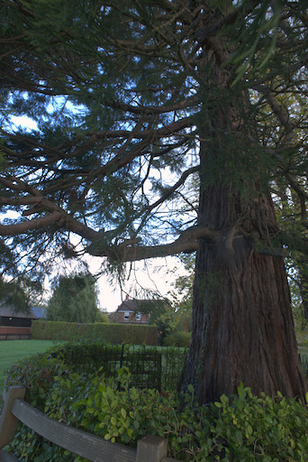
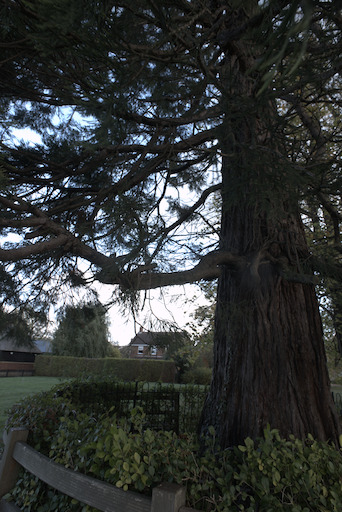
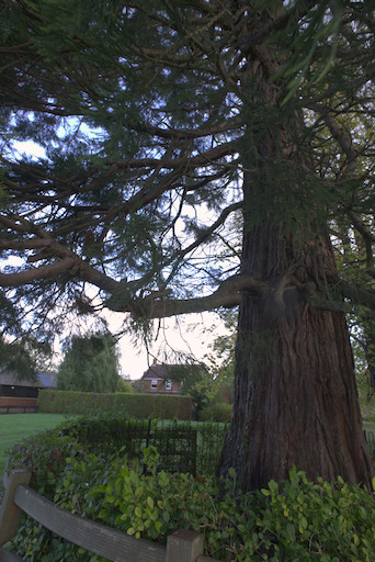
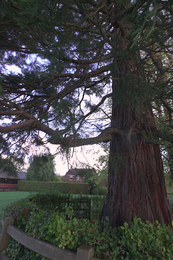
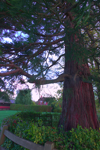
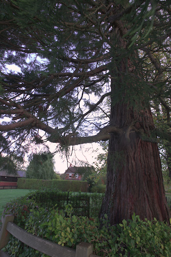
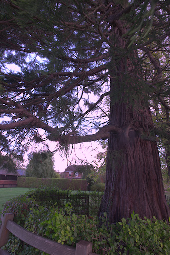
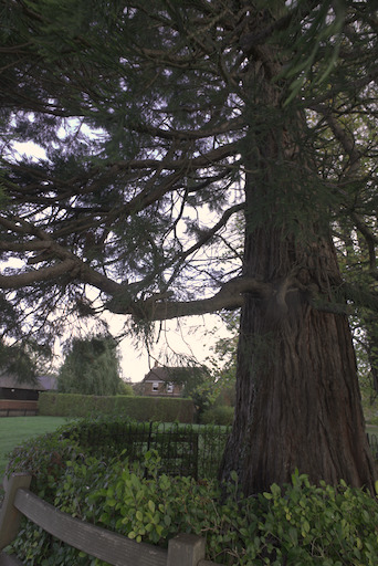
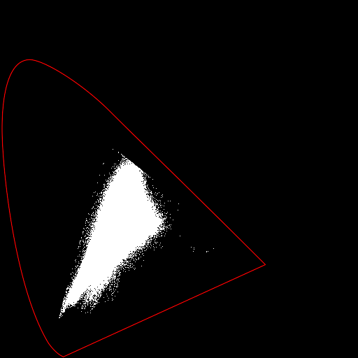
We take a raw image from a camera, convert it to XYZ with dcraw, and from there to xyY.
set SRCRAW=%PICTLIB%20171029\AGA_3443.NEF

%DCRAW% -v -4 -w -W -o 5 -T -O cbc_src.tiff %SRCRAW%

%IM7DEV%magick ^
  cbc_src.tiff ^
  -strip ^
  -set colorspace XYZ ^
  -colorspace xyY ^
  -depth 32 ^
  -define quantum:format=floating-point ^
  cbc_xyy.miff
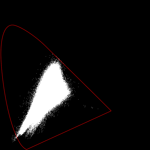
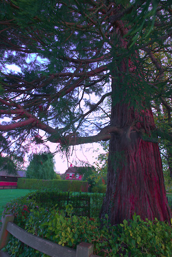
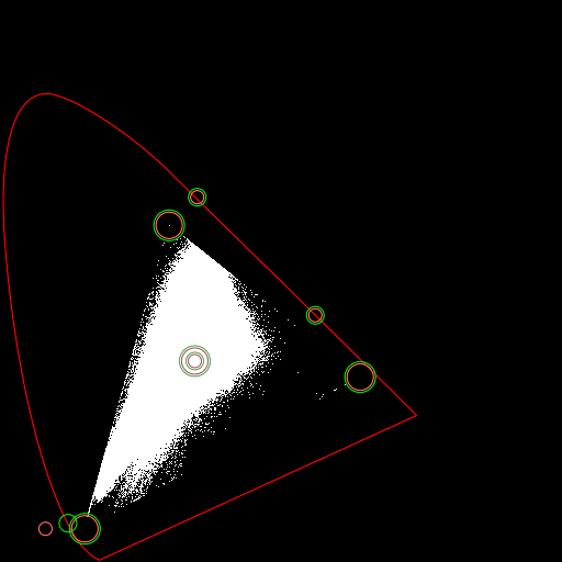
The script xyyHorse.bat takes an image encoded in xyY space, and draws it as a chart, white where any pixels have that xy, otherwise black, superimposing a red horseshoe. It also creates a small sRGB JPG version of the input xyY image. A change in position on the xy chart represents a change in colour in the sRGB image.
call %PICTBAT%xyyHorse ^ cbc_xyy.miff cbc_xyy.png |
|
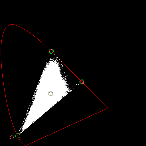
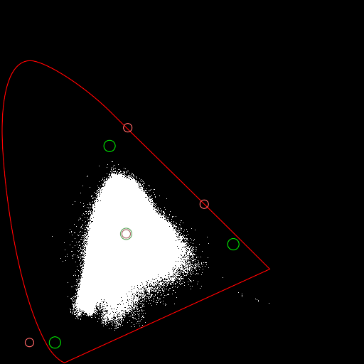
Some pixels are outside the horseshoe.
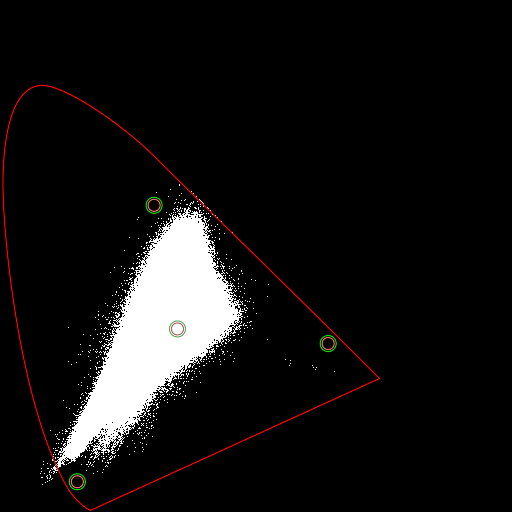
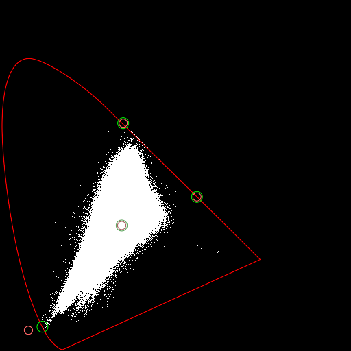
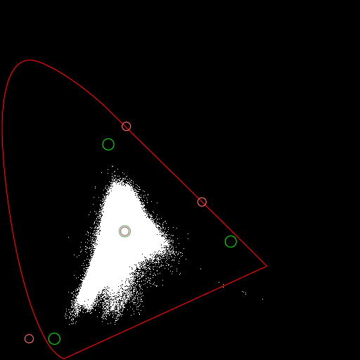
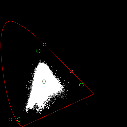
With the default options, the module does a round-trip of cartesian to barycentric using the input primaries and WP, then barycentric to cartesian using the output primaries and WP. As the input and output primaries and WP are the same, this makes no changes.
%IM7DEV%magick ^
  cbc_xyy.miff ^
  -set colorspace xyY ^
  -process 'barymap v' ^
  -depth 32 ^
  -define quantum:format=floating-point ^
  cbc_tx0.miff 2>cbc_txverb0.lis
call %PICTBAT%xyyHorse ^ cbc_tx0.miff cbc_tx0.png call %PICTBAT%drPrimWp ^ cbc_tx0.png cbc_tx0.png ^ cbc_txverb0.lis |

|
Small red circles show input primaries and WP. Slightly larger green circles show output primaries and WP. The defaults are for sRGB, but there is no conversion so these have no significance. However, they show us that many colours are outside the sRGB triangle.
We might assume that chromaticities shown on this diagram are reasonably accurate, except that colours should not be outside the horseshoe. We assume the conversion from camera sensor values to XYZ is not accurate for this image, and that we don't know what an accurate conversion would be.
If the goal is conversion to sRGB, we need to do something to the chromaticities outside the triangle.
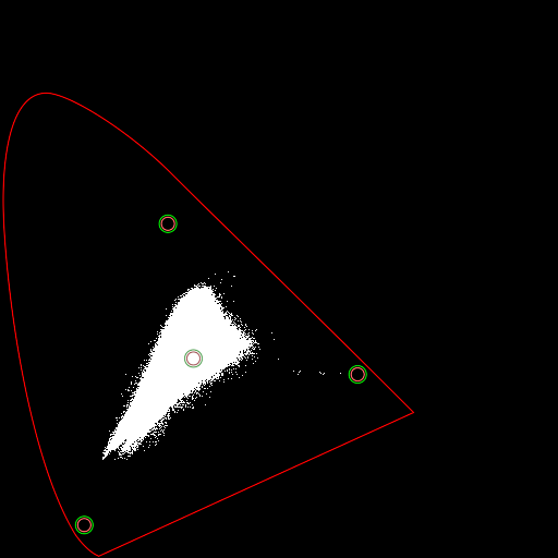
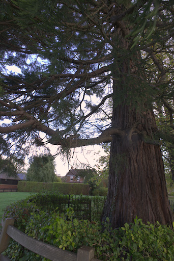
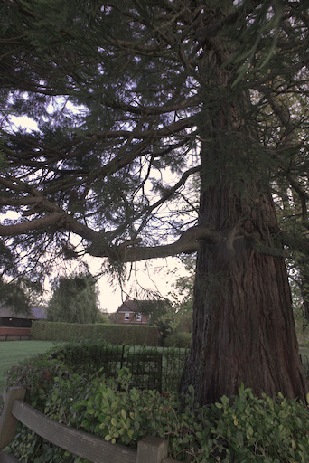
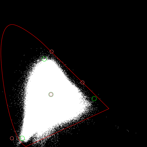
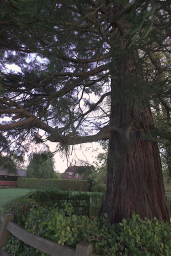
As a point of comparison, we use dcraw to create an sRGB version, then convert that to xyY.
%DCRAW% -v -6 -w -W -o 0 -T -O cbc_dcr.tiff %SRCRAW%

%IM7DEV%magick cbc_dcr.tiff -colorspace xyY cbc_dcr.miff
call %PICTBAT%xyyHorse ^ cbc_dcr.miff cbc_dcr.png call %PICTBAT%drPrimWp ^ cbc_dcr.png cbc_dcr.png ^ cbc_txverb.lis |
|
We can see that:
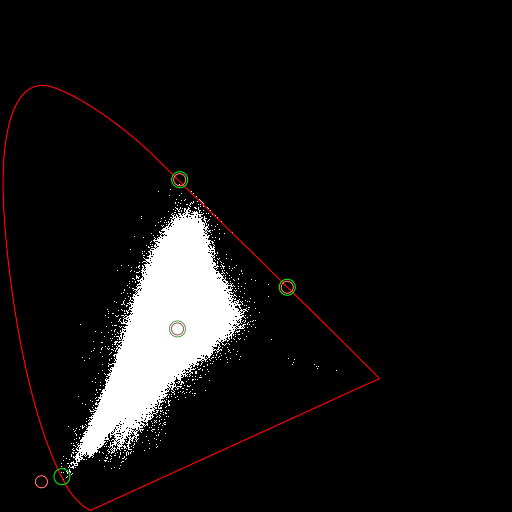
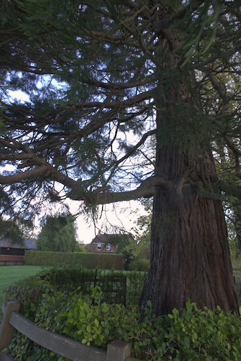
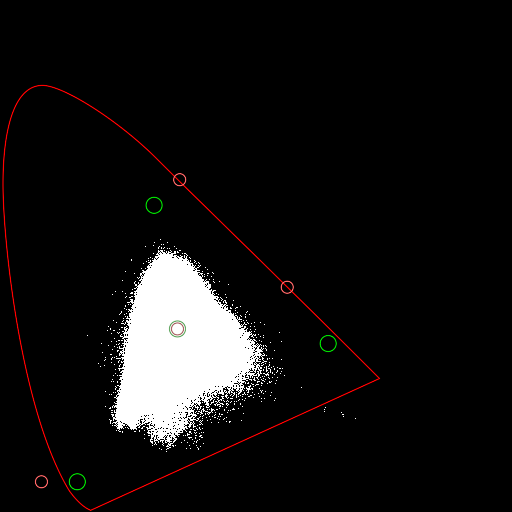
We push the colours that are beyond blue into the horseshoe. This shifts all colours towards the green and red primaries.
The common colours form an approximate triangle. From the Default options section above, we manually choose coordinates on the locus near the corners of the triangle, and we want to push blue chromaticities inwards, so for the input blue primary we choose coordinates outside the locus, at the extreme of the used chromaticities.
set INPRIM=0.56,0.44,0.35,0.65,0.08,0.06
set OUTPRIM=0.56,0.44,0.35,0.65,0.12,0.07
%IM7DEV%magick ^
  cbc_xyy.miff ^
  -set colorspace xyY ^
  -process 'barymap ign inPrim %INPRIM% outPrim %OUTPRIM% v' ^
  -depth 32 ^
  -define quantum:format=floating-point ^
  cbc_tx1.miff 2>cbc_txverb.lis
call %PICTBAT%xyyHorse ^ cbc_tx1.miff cbc_tx1.png call %PICTBAT%drPrimWp ^ cbc_tx1.png cbc_tx1.png ^ cbc_txverb.lis |
|
The circles show we are moving the blue primary towards the WP.
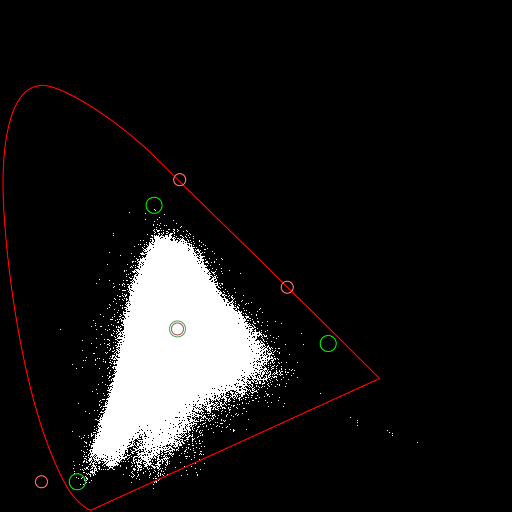
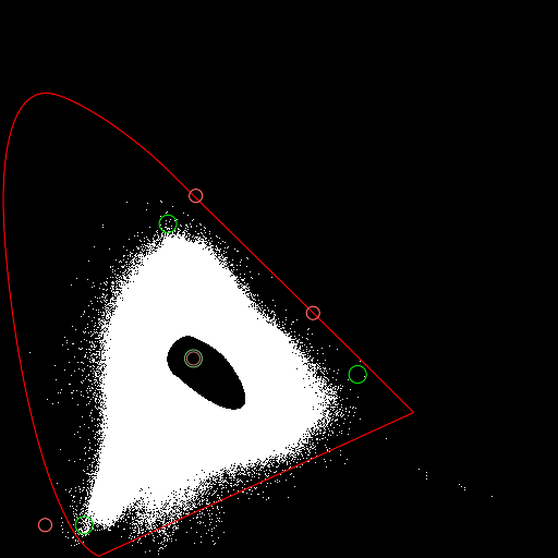
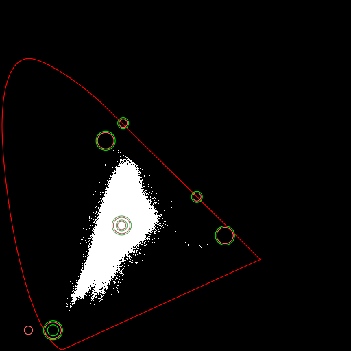
As the previous example, but we don't ignore the white point. So this won't shift all the colours: any colours within the WP-green-red triangle will be unchanged. Other colours will be pushed towards the green-WP line, or the red-WP line.
%IM7DEV%magick ^
  cbc_xyy.miff ^
  -set colorspace xyY ^
  -process 'barymap inPrim %INPRIM% outPrim %OUTPRIM% v' ^
  -depth 32 ^
  -define quantum:format=floating-point ^
  cbc_tx2.miff 2>cbc_txverb.lis
call %PICTBAT%xyyHorse ^ cbc_tx2.miff cbc_tx2.png call %PICTBAT%drPrimWp ^ cbc_tx2.png cbc_tx2.png ^ cbc_txverb.lis |
|
I consider this a satisfactory transformation that makes all colours fit inside the horseshoe. If that is the goal, then we have achieved it.
As the previous example, but we also clamp to the triangles.
%IM7DEV%magick ^
  cbc_xyy.miff ^
  -set colorspace xyY ^
  -process 'barymap inPrim %INPRIM% outPrim %OUTPRIM% clB v' ^
  -depth 32 ^
  -define quantum:format=floating-point ^
  cbc_tx2a.miff 2>cbc_txverb.lis
call %PICTBAT%xyyHorse ^ cbc_tx2a.miff cbc_tx2a.png call %PICTBAT%drPrimWp ^ cbc_tx2a.png cbc_tx2a.png ^ cbc_txverb.lis |
|
Clamping to the triangle has caused many chromaticities that were outside the triangle to be mapped to the same chromaticities on the edge of the triangle, which loses detail.
We map the input chromaticities triangle to the triangle of the sRGB primaries.
%IM7DEV%magick ^
  cbc_xyy.miff ^
  -set colorspace xyY ^
  -process 'barymap inPrim %INPRIM% outPrim sRGB v' ^
  -depth 32 ^
  -define quantum:format=floating-point ^
  cbc_tx3.miff  2>cbc_txverb.lis
call %PICTBAT%xyyHorse ^ cbc_tx3.miff cbc_tx3.png call %PICTBAT%drPrimWp ^ cbc_tx3.png cbc_tx3.png ^ cbc_txverb.lis |
|
The green circles (the output primaries) no longer coincide with the red circles (the input primaries). In particular, the red primary has shifted heavily, creating a reddish tint. Chromaticities that were outside the input triangle will also be outside the output triangle. This direct mapping to sRGB has greatly changed xy values, so is probably not satisfactory. But it is interesting, so we will stick with it for now.
As the previous example, but we also use a power function to decrease chroma.
%IM7DEV%magick ^
  cbc_xyy.miff ^
  -set colorspace xyY ^
  -process 'barymap inPrim %INPRIM% pow 1.2 outPrim sRGB v' ^
  -depth 32 ^
  -define quantum:format=floating-point ^
  cbc_tx4.miff 2>cbc_txverb.lis
call %PICTBAT%xyyHorse ^ cbc_tx4.miff cbc_tx4.png call %PICTBAT%drPrimWp ^ cbc_tx4.png cbc_tx4.png ^ cbc_txverb.lis |
|
Just for fun, we go in the opposite direction, using a power function to increase chroma.
%IM7DEV%magick ^
  cbc_xyy.miff ^
  -set colorspace xyY ^
  -process 'barymap inPrim %INPRIM% pow 0.8 outPrim sRGB v' ^
  -depth 32 ^
  -define quantum:format=floating-point ^
  cbc_tx5.miff 2>cbc_txverb.lis
call %PICTBAT%xyyHorse ^ cbc_tx5.miff cbc_tx5.png call %PICTBAT%drPrimWp ^ cbc_tx5.png cbc_tx5.png ^ cbc_txverb.lis |
|
Instead of a power functiom, we use a gain function to decrease chroma.
%IM7DEV%magick ^
  cbc_xyy.miff ^
  -set colorspace xyY ^
  -process 'barymap inPrim %INPRIM% gain 0.8 outPrim sRGB v' ^
  -depth 32 ^
  -define quantum:format=floating-point ^
  cbc_tx6.miff 2>cbc_txverb.lis
call %PICTBAT%xyyHorse ^ cbc_tx6.miff cbc_tx6.png call %PICTBAT%drPrimWp ^ cbc_tx6.png cbc_tx6.png ^ cbc_txverb.lis |
|
We use a gain2 function to decrease chroma.
%IM7DEV%magick ^
  cbc_xyy.miff ^
  -set colorspace xyY ^
  -process 'barymap inPrim %INPRIM% gain2 -0.9 outPrim sRGB v' ^
  -depth 32 ^
  -define quantum:format=floating-point ^
  cbc_tx6a.miff 2>cbc_txverb.lis
call %PICTBAT%xyyHorse ^ cbc_tx6a.miff cbc_tx6a.png call %PICTBAT%drPrimWp ^ cbc_tx6a.png cbc_tx6a.png ^ cbc_txverb.lis |
|
We use a function with both gain2 and gain to decrease chroma.
%IM7DEV%magick ^
  cbc_xyy.miff ^
  -set colorspace xyY ^
  -process 'barymap inPrim %INPRIM% gain2 -0.8335 gain 1.08335 outPrim sRGB v' ^
  -depth 32 ^
  -define quantum:format=floating-point ^
  cbc_tx6b.miff 2>cbc_txverb.lis
call %PICTBAT%xyyHorse ^ cbc_tx6b.miff cbc_tx6b.png call %PICTBAT%drPrimWp ^ cbc_tx6b.png cbc_tx6b.png ^ cbc_txverb.lis |

|
We use a bias function to increase chroma.
%IM7DEV%magick ^
  cbc_xyy.miff ^
  -set colorspace xyY ^
  -process 'barymap inPrim %INPRIM% bias 0.05 outPrim sRGB v' ^
  -depth 32 ^
  -define quantum:format=floating-point ^
  cbc_tx7.miff 2>cbc_txverb.lis
call %PICTBAT%xyyHorse ^ cbc_tx7.miff cbc_tx7.png call %PICTBAT%drPrimWp ^ cbc_tx7.png cbc_tx7.png ^ cbc_txverb.lis |
|
The hole, centred on the white point, shows we have no neutral colours. The hole would be circular if the three triangles were the same shape, and we were not converting to a different set of primaries.
We can run the module multiple times, with the output of the first used as input to the second.
Here, the first pass maps colours from INPRIM to OUTPRIM. The second pass doesn't map between triangles, but simply clamps colours to the sRGB triangle of primaries.
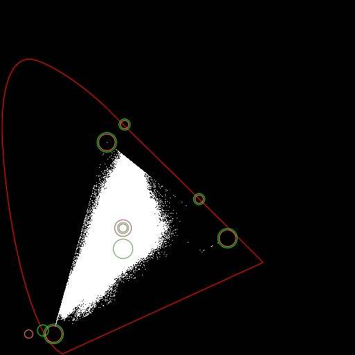
%IM7DEV%magick ^
  cbc_xyy.miff ^
  -set colorspace xyY ^
  -process 'barymap inPrim %INPRIM% outPrim %OUTPRIM% v' ^
  -process 'barymap ign inPrim sRGB clampBarycentric outPrim sRGB v' ^
  -depth 32 ^
  -define quantum:format=floating-point ^
  cbc_tx8.miff 2>cbc_txverb.lis
call %PICTBAT%xyyHorse ^ cbc_tx8.miff cbc_tx8.png call %PICTBAT%drPrimWp ^ cbc_tx8.png cbc_tx8.png ^ cbc_txverb.lis |

|
The white area has a sharp edge, meaning many colours have been clipped to the triangle.
There were two passes of barymap, so we have two sets of circles. The first set is the smallest, the second set is larger, and so on. Within each set, red marks the input, and green marks the output.
In the second pass, we use sRGB primaries for input and output, but shift the white point. As in the previous example, we clamp to the sRGB tiangle.
%IM7DEV%magick ^
  cbc_xyy.miff ^
  -set colorspace xyY ^
  -process 'barymap inPrim %INPRIM% outPrim %OUTPRIM% v' ^
  -process 'barymap inPrim sRGB clampBarycentric outPrim sRGB outWP 0.34567,0.3 v' ^
  -depth 32 ^
  -define quantum:format=floating-point ^
  cbc_tx8a.miff 2>cbc_txverb.lis
call %PICTBAT%xyyHorse ^ cbc_tx8a.miff cbc_tx8a.png call %PICTBAT%drPrimWp ^ cbc_tx8a.png cbc_tx8a.png ^ cbc_txverb.lis |
|
This has slightly reduced clipping, but the image has become more red, most noticably in the sky.
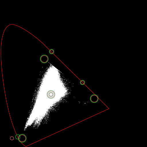
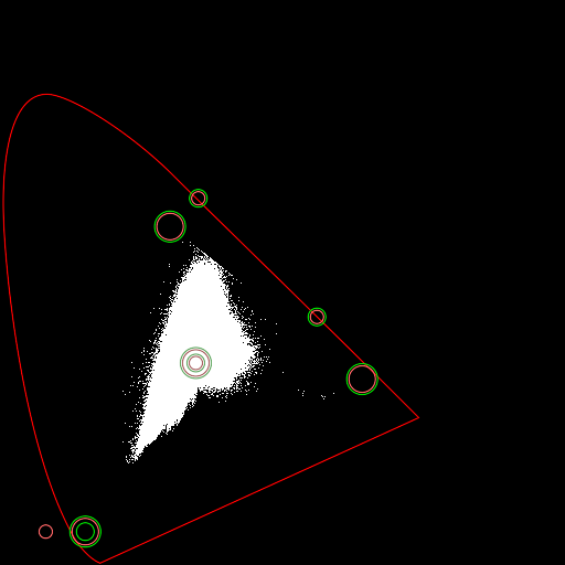
This is as Two passes, but applying a gain in the first pass to reduce clipping.
%IM7DEV%magick ^
  cbc_xyy.miff ^
  -set colorspace xyY ^
  -process 'barymap inPrim %INPRIM% gain 0.85 outPrim %OUTPRIM% v' ^
  -process 'barymap ign inPrim sRGB clampBarycentric outPrim sRGB v' ^
  -depth 32 ^
  -define quantum:format=floating-point ^
  cbc_tx9.miff 2>cbc_txverb.lis
call %PICTBAT%xyyHorse ^ cbc_tx9.miff cbc_tx9.png call %PICTBAT%drPrimWp ^ cbc_tx9.png cbc_tx9.png ^ cbc_txverb.lis |

|
Some colours have been clipped to the triangle, but this doesn't seem excessive. We can reduce the clipping near blue by tweaking the output blue primary.
This is as the previous example, but adjusting the output blue primary to be the sRGB coordinates.
set OUTPRIM2=0.56,0.44,0.35,0.65,0.15,0.06

%IM7DEV%magick ^
  cbc_xyy.miff ^
  -set colorspace xyY ^
  -process 'barymap inPrim %INPRIM% gain 0.85 outPrim %OUTPRIM2% v' ^
  -process 'barymap ign inPrim sRGB clampBarycentric outPrim sRGB v' ^
  -depth 32 ^
  -define quantum:format=floating-point ^
  cbc_tx10.miff 2>cbc_txverb.lis
call %PICTBAT%xyyHorse ^ cbc_tx10.miff cbc_tx10.png call %PICTBAT%drPrimWp ^ cbc_tx10.png cbc_tx10.png ^ cbc_txverb.lis |

|
This has pushed colours into purple, which make the sky less realistic. I prefer the previous version. But we can reduce the chroma of purples.
This is as the previous example, but reducing the chroma of the purples. As we see the diagram after the final pass, setting the parameters is most easily done in that pass.
%IM7DEV%magick ^
  cbc_xyy.miff ^
  -set colorspace xyY ^
  -process 'barymap inPrim %INPRIM% gain 0.8 outPrim %OUTPRIM2% v' ^
  -process 'barymap ign inPrim sRGB am 180,120,0.7 clampBarycentric outPrim sRGB v' ^
  -depth 32 ^
  -define quantum:format=floating-point ^
  cbc_tx11.miff 2>cbc_txverb.lis
call %PICTBAT%xyyHorse ^ cbc_tx11.miff cbc_tx11.png call %PICTBAT%drPrimWp ^ cbc_tx11.png cbc_tx11.png ^ cbc_txverb.lis |
|
The purples are less saturated.
We might decide we like the results near the blue primary from Using gain to reduce clipping image cbc_tx9.miff but the green and red primaries from Tweak both gains, map to sRGB image cbc_tx6b.miff blah.
We can composite one xyY image over the other with a mask. We make the mask from one of the xyY versions of the input image, cbc_xyy.miff. The mask is black at the blue primary, fading to white at the green primary. The Y channel is not relevant for making the mask, so we make it zero. Which blue primary? The final one used for cbc_tx9.miff, which is the sRGB blue primary, which is (x,y)=(0.15,0.06).
The difference is 0.0 to 1.0, with the maximum at the opposite corner of the colour cube. but the Y channel doesn't vary so the maximum is sqrt(2)/sqrt(3) which is 0.8265. The distance between the blue and green primaries is hypot (0.15-0.3, 0.06-0.6)/sqrt(3) which is 0.3236. (The distance between the blue and red primaries is similar.)
After compositing the two xyY images with the mask, we use barymap to clamp the chromaticities (xy values) to the sRGB triangle.
%IM7DEV%magick ^
  cbc_xyy.miff ^
  -set colorspace sRGB ^
  -channel B -evaluate set 0 +channel ^
  ( +clone ^
    -fill RGB(15%%,6%%,0) -colorize 100 ^
  ) ^
  -compose Difference -composite ^
  -grayscale RMS ^
  -level 0,32.36%% ^
  -set colorspace sRGB ^
  -write mpr:MASK ^
  +delete ^
  cbc_tx9.miff ^
  cbc_tx6b.miff ^
  mpr:MASK ^
  -alpha off ^
  -compose Over -composite ^
  -process 'barymap ign inPrim sRGB clampBarycentric outPrim sRGB v' ^
  -depth 32 ^
  -define quantum:format=floating-point ^
  cbc_blnd.miff 2>cbc_blnd.lis
call %PICTBAT%xyyHorse ^ cbc_blnd.miff cbc_blnd.png call %PICTBAT%drPrimWp ^ cbc_blnd.png cbc_blnd.png ^ cbc_blnd.lis |


|
When we are happy with a transformation, we can create a hald clut (aka 3D clut) from that transformation, and directly use that clut on any image encoded in xyY space. The hald:16 is an image with all 8-bit values in all channels, ie a 256*256*256 cube.
First, make the hald clut:
%IM7DEV%magick ^
  hald:16 ^
  -set colorspace xyY ^
  -process 'barymap inPrim %INPRIM% gain 0.85 outPrim %OUTPRIM% v' ^
  -process 'barymap ign inPrim sRGB clampBarycentric outPrim sRGB v' ^
  -depth 32 ^
  -define quantum:format=floating-point ^
  cbc_hald.miff
Apply the hald clut:
%IM7DEV%magick ^
  cbc_xyy.miff ^
  cbc_hald.miff ^
  -set colorspace xyY ^
  -hald-clut ^
  -depth 32 ^
  -define quantum:format=floating-point ^
  -alpha off ^
  cbc_txh1.miff
Note: this needs "-alpha off", otherwise xyyHorse.bat can't read it.
We are using xyY as the three input and output channels for the hald clut, but the clut doesn't change Y values. We only need a 2D clut, but IM doesn't have that facility.
call %PICTBAT%xyyHorse ^ cbc_txh1.miff cbc_txh1.png |

|
The module makes only one pass over the image. The processing per pixel can be complex, depending on the options chosen:
We have created large files we no longer need, so delete them.
del cbc_src.tiff
rem del cbc_*.miff
Gain, bias and power could be automatically chosen.
Software could analyze a xyY histogram to determine bounding primaries. For example, to find the green primary, walk down the rows until no more than X% of pixels are outside the triangle. This would assist in answering the question, "Which colorspace best encodes this image?"
The module provides almost infinite possibilities. In practice, a small number of presets might be designed for common circumstances. An automated system might choose the most appropriate of these according to statistics gathered from the image.
The gain-bias-power options currently shift chroma (the distance of a colour from the white point) the same amount in all directions. This could be split to operate in x and y directions independently.
Metrics might be useful, eg:
As always, we need to decide on trade-offs: accuracy versus clipping versus "looks good".
This process might be better if performed in a more perceptually uniform colorspace, eg on uv channels of Luv.
For convenience, .bat scripts are also available in a single zip file. See Zipped BAT files.
rem %1 input image in xyY space.
rem %2 output black/white histogram with horseshoe.
rem Also creates small sRGB version of input image.

%IM7DEV%magick ^
  %1 ^
  -strip ^
  ( +clone ^
    -set colorspace xyY ^
    -resize 512x512 ^
    -colorspace sRGB ^
    +write %~n1_sm.jpg ^
    +delete ^
  ) ^
  -process 'plotrg dim 512 norm verbose' ^
  -flip ^
  -fill White +opaque Black ^
  -set colorspace sRGB ^
  %2

if ERRORLEVEL 1 exit /B 1

call %PICTBAT%cieHorseshoe %2 %2

if ERRORLEVEL 1 exit /B 1
rem %1 is input chromaticity diagram.
rem %2 is output, with primaries and white point shown.
rem %3 is file of text verbose output from process module barymap.
@rem
@rem This picks up every inPrim etc,
@rem and draws them in different sizes.

@if "%1"=="" findstr /B "rem @rem" %~f0 & exit /B 1

@setlocal enabledelayedexpansion

@call echoOffSave

set INFILE=%1
set OUTFILE=%2
set BARYLIS=%3

set inPrim=
set inWP=
set outPrim=
set outWP=

set NinPrim=0
set NinWP=0
set NoutPrim=0
set NoutWP=0

:: stat is 1 for "In:", 2 for "Out:", 0 for neither
set stat=0

for /F "usebackq tokens=1-2 delims=* " %%A in (%BARYLIS%) do (
  rem echo read [%%A] [%%B] [!stat!]
  if /I "%%A"=="In:" set stat=1
  if /I "%%A"=="Out:" set stat=2
  if /I "%%A"=="nAngMults" set stat=0
  if /I "%%A"=="inPrim" (
    echo inPrim %%B
    set inPrim[!NinPrim!]=%%B
    set /A NinPrim+=1
  )
  if /I "%%A"=="inWP" (
    echo inWP %%B
    set inWP[!NinWP!]=%%B
    set /A NinWP+=1
  )
  if /I "%%A"=="outPrim" (
    echo outPrim %%B
    set outPrim[!NoutPrim!]=%%B
    set /A NoutPrim+=1
  )
  if /I "%%A"=="outWP" (
    echo outWP %%B
    set outWP[!NoutWP!]=%%B
    set /A NoutWP+=1
  )
)

echo %NinPrim% %NinWP% %NoutPrim% %NoutWp%

set /A lastinPrim = NinPrim-1
set /A lastinWP   = NinWP-1
set /A lastoutPrim  = NoutPrim-1
set /A lastoutWP  = NoutWP-1

set sDRAWip=
for /L %%N in (0,1,%lastinPrim%) do (
  set prev=
  set i=0
  for %%A in (!inPrim[%%N]!) do (
    if "!prev!"=="" (
      set prev=%%A
    ) else (
      set /A rad=%%N*6+6
      echo ip !prev! and %%A !rad!
      set sDRAWip!i![%%N]=-draw "translate %%[fx:w*!prev!],%%[fx:h-h*%%A] circle 0,0,0,!rad!"
      set prev=
      set /A i+=1
    )
  )
  set sDRAWip=!sDRAWip! !sDRAWip0[%%N]! !sDRAWip1[%%N]! !sDRAWip2[%%N]!
)

set sDRAWiw=
for /L %%N in (0,1,%lastinWP%) do (
  set prev=
  for %%A in (!inWP[%%N]!) do (
    if "!prev!"=="" (
      set prev=%%A
    ) else (
      set /A rad=%%N*6+6
      echo iw !prev! and %%A !rad!
      set sDRAWiw[%%N]=-draw "translate %%[fx:w*!prev!],%%[fx:h-h*%%A] circle 0,0,0,!rad!"
      set prev=
      set /A i+=1
    )
  )
  set sDRAWiw=!sDRAWiw! !sDRAWiw[%%N]!
)

set sDRAWop=
for /L %%N in (0,1,%lastoutPrim%) do (
  set prev=
  set i=0
  for %%A in (!outPrim[%%N]!) do (
    if "!prev!"=="" (
      set prev=%%A
    ) else (
      set /A rad=%%N*6+8
      echo op !prev! and %%A  !rad!
      set sDRAWop!i![%%N]=-draw "translate %%[fx:w*!prev!],%%[fx:h-h*%%A] circle 0,0,0,!rad!"
      set prev=
      set /A i+=1
    )
  )
  set sDRAWop=!sDRAWop! !sDRAWop0[%%N]! !sDRAWop1[%%N]! !sDRAWop2[%%N]!
)

set sDRAWow=
for /L %%N in (0,1,%lastoutWP%) do (
  set prev=
  for %%A in (!outWP[%%N]!) do (
    if "!prev!"=="" (
      set prev=%%A
    ) else (
      set /A rad=%%N*6+8
      echo ow !prev! and %%A !rad!
      set sDRAWow[%%N]=-draw "translate %%[fx:w*!prev!],%%[fx:h-h*%%A] circle 0,0,0,!rad!"
      set prev=
      set /A i+=1
    )
  )
  set sDRAWow=!sDRAWow! !sDRAWow[%%N]!
)

echo ip = %sDRAWip%
echo op = %sDRAWop%

%IMG7%magick ^
  %INFILE% ^
  -fill None ^
  -stroke #f66 ^
  %sDRAWip% ^
  -stroke #a66 ^
  %sDRAWiw% ^
  -stroke #0d0 ^
  %sDRAWop% ^
  -stroke #6a6 ^
  %sDRAWow% ^
  %OUTFILE%

call echoRestore

@endlocal
All images on this page were created by the commands shown, using:
%IMG7%magick -version
Version: ImageMagick 7.1.0-49 Q16-HDRI x64 7a3f3f1:20220924 https://imagemagick.org
Copyright: (C) 1999 ImageMagick Studio LLC
License: https://imagemagick.org/script/license.php
Features: Cipher DPC HDRI OpenCL
Delegates (built-in): bzlib cairo freetype gslib heic jng jp2 jpeg jxl lcms lqr lzma openexr pangocairo png ps raqm raw rsvg tiff webp xml zip zlib
Compiler: Visual Studio 2022 (193331630)
To improve internet download speeds, some images may have been automatically converted (by ImageMagick, of course) from PNG or TIFF or MIFF to JPG.
Source file for this web page is colbarycoord.h1. To re-create this web page, execute "procH1 colbarycoord".
This page, including the images, is my copyright. Anyone is permitted to use or adapt any of the code, scripts or images for any purpose, including commercial use.
Anyone is permitted to re-publish this page, but only for non-commercial use.
Anyone is permitted to link to this page, including for commercial use.
Page version v1.0 5-December-2018.
Page created 30-Sep-2022 16:14:54.
Copyright © 2022 Alan Gibson.